Study of the Discrete Shear Gap Technique in Timoshenko Beam
Elements
Wong, F.T.1* and Sugianto, S.2
Abstract: A major difficulty in formulating a finite element for shear-deformable beams, plates, and shells is the shear locking phenomenon. A recently proposed general technique to overcome this difficulty is the discrete shear gap (DSG) technique. In this study, the DSG technique was applied to the linear, quadratic, and cubic Timoshenko beam elements. With this technique, the displacement-based shear strain field was replaced with a substitute shear strain field obtained from the derivative of the interpolated shear gap. A series of numerical tests were conducted to assess the elements performance. The results showed that the DSG technique works perfectly to eliminate the shear locking. The resulting deflection, rotation, bending moment, and shear force distributions were very accurate and converged optimally to the corresponding analytical solutions. Thus the beam elements with the DSG technique are better alternatives than those with the classical selective-reduced integration.
Keywords: Discrete shear gap; selective-reduced integration; shear locking; Timoshenko beam element.
Introduction
Structural models of beam, plate, and shell are the earliest problems to which the finite element method was developed and applied in the early 1960s [1].In the early development, the classical theory of beam, plate, and shell, which neglects shear deformation, was used as the basis to develop a variety of beam, plate, and shell elements. Subsequently finite element developers preferred to use the shear-deformable theory as the basis to develop beam, plate, and shell elements since this theory requires a low order continuity requirement, i.e. C0 continuity,
and is more general than the classical theory. A major difficulty in formulating a finite element based on the shear-deformable theory is a phenomenon in which an element becomes excessively stiff as the element becomes very thin, which is well-known as shear locking.
Literatures on finite elements of shear deformable beam, plate, and shell contain innumerable concepts, techniques, or tricks to overcome the difficulty of shear locking.
1 Department of Civil Engineering, Petra Christian University,
Surabaya, INDONESIA
2 Master Program of Civil Engineering, Petra Christian University,
Surabaya, INDONESIA
*Corresponding author; e-mail: [email protected]
Note: Discussion is expected before June, 1st 2017, and will be
published in the “Civil Engineering Dimension”, volume 19, number 2, September 2017.
Received 10 December 2016; revised 22 February 2017; accepted 04 March 2017.
A well-known early technique is the selective reduced integration technique [2,3], in which the order of numerical integration for calculating the shear related part of the stiffness matrix is deliberately reduced. While this simple technique works well for Timoshenko beam elements, it produces a quadrilateral Reissner-Mindlin plate bending element that contains spurious zero strain energy modes [3] and it is not applicable to a triangular plate bending element [4]. Other well-known techniques are the assumed natural shear strain method [5,6], the discrete Kirchhoff approach-es [7-9], and the mixed interpolation of tensorial component approach [10]. From the literature it is recognized that a successful locking-free technique for a quadrilateral element is usually cannot be directly applied to a triangular element and vice versa.
Although the DSG technique was firstly introduced in the context of Timoshenko beam [11], subsequent applications of the technique were focused on the plate and shell problems. In the context of the Kriging-based finite element method [16], the application of the DSG technique has been studied by Wong and Sulistio [17]. It was found that the DSG is effective to eliminate shear locking for a Kriging-based element with cubic polynomial basis, but not effective for those with quadratic and linear bases. In the context of the standard FEM, however, there has been no formulation and numerical test of the DSG technique on higher-order Timoshenko beam elements. It is thus the aim of this paper to study the application of DSG technique in the standard linear, quadratic, and cubic Timoshenko beam elements. The application of the DSG is accom-plished by replacing the shear strain-displacement matrix with the one derived based on the DSG concept. A series of numerical tests is carried out to evaluate the performance of the DSG beam ele-ments, in particular to evaluate the effectiveness of the DSG technique at eliminating shear locking. The comparison is made with beam elements using the selective-reduced as well as full integrations.
Timoshenko Beam Elements
Governing Equations
A beam model of length L with the cross sectional area A and moment of inertia I is considered. The material properties are a constant modulus elasticity E and a constant Poisson‟s ratio ν. The beam is subjected to a static transversal distributed load q=q(x). The displacement of any point in the beam can be expressed in terms of two independent field variables, i.e. the vertical displacement of the neutral axis, or, the deflection w=w(x) and the cross section rotation β= β(x). The coordinate system and sign convention for positive w and β are depicted in Figure 1.
The weak form of the governing equation for static deformation of the Timoshenko beam model is given as:
0 , , 0( , ) ( , ) 0
L L L
xEI xdx wx kGA wx dx q wdx
for all admissible δw and δβ (1a)
Figure 1. Coordinate System and Positive Directions for the Deflection and Rotation
In this equation, δw and δβ are a virtual deflection and a virtual cross section rotation, respectively. The
term „admissible‟ means that the δw and δβ satisfy the requirements of C0 continuity and homogenous
displacement boundary conditions. The constant G is the shear modulus given as
2(1
)
E
G
(1b)and k is a shear correction factor that is dependent upon the cross-section geometry and Poisson ratio [18]. The comma signifies the first derivative with respect to the variable next to it (i.e. x).
The bending moment M and shear force Q along the beam are given as
,
xM
EI
(2)( ,
x)
Q
kGA w
(3)Finite Element Discretization
Let the beam is subdivided into Nel elements and
consider a typical element having n nodes. The deflection and rotation along the element are approximated as follows:
1
n
i i w
i
w
N w
N
d
(4)
1
n i i
i
N
N
d
(5) in which [Nw] is the shape function matrix for the deflection, i.e.
Nw N1 0 N2 0 Nn 0
(6)[Nβ] is the shape function matrix for the rotation, i.e.
0
10
20
n
N
N
N
N
(7)and {d} is the unknown nodal displacement vector, i.e.
T1 1 2 2 n n
d
w
w
w
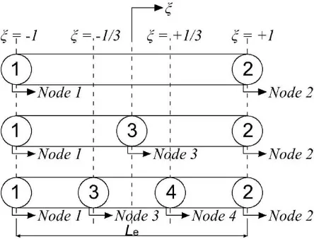
(8)The number of element node n depends on the polynomial degree employed to approximate w and β, that is, n=2 for a linear element, n=3 for a quadratic element, and n=4 for a cubic element, as shown in Figure 2.
Using the isoparametric mapping concept, the coordinate x is expressed in terms of natural coor-dinate
[ 1, 1]
in the same manner as the approximation for the field variables, i.e.1
n i i i
x
N x
(9)where xi, i=1,…,n are the nodal coordinates. The expression for the shape functions are listed in Table 1 in terms of ξ. The Jacobian of the mapping is defined as
,
Figure 2. One-dimensional Linear, Quadratic, and Cubic Elements
Table 1. Shape Functions for a 1D Element of Two to Four Nodes (taken from [10], p. 343) with the Numbering Labels as Shown in Figure 2.
If the element has node 3
If the element has nodes 3 and 4
N1= 12
(1
)
12(12) 161( 9 3291) N2= 12(1
) 12(1
2)
161(9
3
2
9
1)
N3= (1
2) 161(27372277)N4= 161( 27 392279)
Substituting Equations (4) and (5) into Equation (1) and carrying out the standard finite element formulation procedure yield the element system of equations
k
d f (11)In this equation, the element stiffness matrix [k] is made up of two parts, namely the stiffness asso-ciated with bending deformation, [k]b, and the
stiff-ness associated with shear deformation, [k]s,
k
k
b
k
s (12)
1 Tb 1
[
]
[
]
k
B
EI B
J d
(13)
1T
s 1([ w] [ ]) ([ w] [ ])
k
B N kGA B N J d
(14)In Equations (13) and (14),
1
1 2
[Bw] J [N, 0 N , 0 Nn, 0]
(15)
1
1 2
[B] J [0 N, 0 N , 0 Nn, ]
(16)
The element nodal force vector {f} is given as
1 T 1[
w]
f
N
q Jd
(17)Numerical Integration
In the present work the integrals in Equations (13), (14), and (17) are evaluated numerically using Gaussian quadrature rule. The number of
inte-gration sampling points to obtain an exact integration result for an element with linear, quadratic, and cubic shape functions are listed in Table 2, assuming q is a linear function. However, it is well known that the use of full integration results in elements that are excessively stiff when they are applied to thin beams, or their convergence rates are not optimal [3,10,19,20] This phenomenon is
known as „shear locking‟. A simple and efficient
technique to eliminate the shear locking is to reduce the number of sampling points for evaluating the shearing part of the stiffness matrix [3]. This tech
-nique is referred to as selective-reduced integration (SRI) technique.
It is worth mentioning here that while the SRI tech-nique is effective to eliminate shear locking, the resulting shear forces are correct only at the inte-gration sampling points. The shear forces evaluated directly at the element nodes are in great error. The shear force distribution fluctuates heavily [20].
Table 2. Number of Integration Sampling Points Required for Full and Selective-reduced Integrations.
Element Technique Bending Stiffness
Shear Stiffness
Force
Linear Full 1 2 2
SRI 1 1 2
Quadratic Full 2 3 3
SRI 2 2 3
Cubic Full 3 5 4
SRI 3 3 4
Note: Full: full integration;
SRI: selective-reduced integration
Discrete Shear Gap Technique
The key idea of the DSG technique is to replace the troublesome discretized shear strain,
w,x
, witha substitute shear strain determined from
inter-polation of „shear gaps‟ at element nodes. Shear gap
at a point x is defined as the increment of displace-ment due to shear deformation from a reference point x0 [11], that is
0 0
( )
x x( ,
x)
x x
w x
dx
w
dx
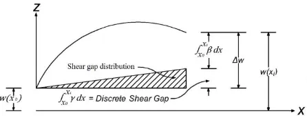
(18)The shear gap can be interpreted as “the difference
between the increase of the actual displacement Δw and the displacement
0
b
( )
x x
w x
dx
(19)which correspond to pure bending” [11]. This inter -pretation is illustrated in Figure 3.
A discrete shear gap (DSG) is the shear gap at an element nodal point with coordinate xi, which can be calculated using Equation (18),
0 0
( )
xi xii i x x
w
w x
w
dx
Figure 3. Shear Gap Interpreted as the Difference bet-ween the Increase of the Total Displacement and the Increase of the Displacement due to Bending [11]
A substitute shear gap field is defined as the inter-polation of the nodal shear gaps,
DSG
( )
1( )
n
i i
i
w
N
w
(21)The substitute shear strain is obtained by differen-tiating Equation (21),
DSG
( )
1,
[
DSG1]{
}
n
i x i
i
N
w
B
w
(22)where
1
DSG1 1
[
B
]
J
N
,
N
n,
(23)
T1
{
w
}
w
w
n (24)Taking node number 1 as the reference point and substituting Equation (5) into Equation (20), the DSGs at nodes i=1, 2, …, n can be expressed as
1 1
(
1)
i
n
i i i i i
w
w
w
N Jd
(25)It is obvious from this equation that the DSG at node 1 is zero, i.e.
1 0
w
. The DSGs at other nodes are given in Table 3.
Using Equation (25) and Table 3, the matrix of discrete shear gaps, Equation (24), can be expressed in terms of the nodal displacement vector as
DSG2
{
w
}
[
B
]{ }
d
(26)The expression of [BDSG2] for the linear beam element
is
1 1
DSG2
1 2
1 1
0
0
0
0
[
]
1
1
B
N Jd
N Jd
(27)Similarly, we can write [BDSG2] matrices for the
quadratic and cubic beam elements (they are, however, too long to be included in this paper). Substituting Equation (26) into Equation (22) yields
DSG
[
B
DSG1][
B
DSG2]{ }
d
[
B
DSG]{ }
d
(28)Thus the DSG concept can be implemented in a computer code by replacing ([Bw] [ N]) matrix in Equation (14) with [BDSG] defined in Equation (28).
Table 3. Discrete Shear Gaps at Nodes other than Node 1 for Different Order of 1D Elements
Element Discrete shear gap
Linear 2 2 1 2 1
1
(
1 i)
ii
w
w
w
N Jd
Quadratic 2 2 1 3 1
1
(
1 i)
ii
w
w
w
N Jd
0 3
3 3 1 i1
(
1 i)
iw
w
w
N Jd
Cubic 2 2 1 4 1
1
(
1 i)
ii
w
w
w
N Jd
1/3 4
3 3 1 i 1
(
1 i)
iw
w
w
N Jd
1/3 4
4 4 1 i1
(
1 i)
iw
w
w
N Jd
Numerical Tests
The linear, quadratic, and cubic beam elements with the DSG technique have been coded using Matlab [21]. For comparison, the standard beam elements with the SRI and full integration have also been coded.
To evaluate the performance of the elements, a series of numerical tests were carried out. The tests included pure bending test, investigation of shear locking, and assessment of the accuracy and convergence characteristics. In all tests, the test problems were analyzed using the linear, quadratic, and cubic DSG beam elements and the standard beam elements with the SRI and full integration. The exception was on the assessment of accuracy through deflection, rotation, bending moment and shear force profiles, in which only the results obtained using the DSG beam elements were presented. The full integration scheme (Table 2) was used to evaluate the integrals in the bending stiffness, shear stiffness, and force terms of the DSG beam elements. The integrals in [BDSG2] matrix,
Equation (26), were also numerically evaluated using full integration to obtain exact integration results. For the quadratic and cubic beam elements, the positions of interior nodes were located in their natural positions, i.e. at x3 Le/ 2 for the quadratic element and at x3Le/ 3 and
x
4
2
L
e/ 3
for the cubic element (see Figure 2, Le is the element length). The employed shear correction factor was given as ([18] as cited in [22])10(1 ) 12 11 k
(29)Pure Bending Test
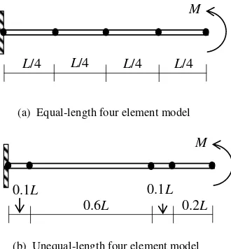
two different meshes, that is, a mesh with four elements of equal length and a mesh with four elements of unequal length shown in Figure 4 [17]. The material, geometrical, and loading parameters were taken as follows: L = 10 m, b = 2 m, E =2000 kN/m2, ν = 0.3, and M = 1 kN-m. Two different
thickness was considered, that is, h = 2 m (L/h = 5), which represents a thick beam, and h=0.001 m (L/h=10000), which represents an extremely thin beam. Certainly, the beam with L/h=10000 is outside the range of practical length-to-thickness ratio. The purpose to include it here is merely to test the tendency of the beam elements to shear locking.
Figure. 4. Meshes of the Cantilever Beam
The beam is in the state of pure bending with constant bending moment M and zero shear stress along the beam. Therefore this problem may be regarded as the patch test for the beam elements. A beam element is said to pass the test if it can reproduce the exact deflection, rotation, bending moment, and shear force for any mesh. The exact deflection and rotation at the right end are given as:
2 exact
( ) 2
ML w L
EI
,
exact
( )L ML
EI
(30)The results of the deflection and rotation at the free end, and the bending moment and shear force at the fixed end were observed and compared to the corresponding exact solutions. For the sake of bre-vity, only the results for the extremely thin beam using the irregular mesh were presented here in Table 4.
It is seen that even for the most critical case (i.e. very thin beam and irregular mesh), the DSG beam elements are not only free from shear locking but also are able to reproduce exact results. In contrast, the results obtained using the linear beam element with full integration are erroneous because of shear locking. While the SRI technique can eliminate the locking, as addressed by Prathap [20], the shear forces calculated directly at the fixed-end node using Equation (3) are in great error, even worse that the shear force obtained with full integration. The overall results showed that that all DSG beam elements passed this pure bending test for both the thick and extremely thin beams, with the regular and irregular meshes. The DSG technique is better than the SRI because the former can give accurate shear force along the beam while the later can only give accurate shear force at the integration sampling points.
Investigation of Shear Locking
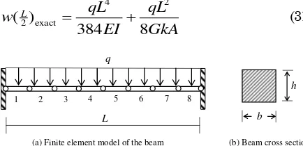
A fixed-fixed supported beam subjected to a uni-formly distributed load (Figure 5) was analyzed to investigate the effectiveness of the DSG in elimi-nating shear locking.. The fixed-fixed supported
beam was chosen because in the authors‟ experience,
this problem is the most critical problem for a shear locking test. The material and geometrical data were the same as in the pure bending test with the uniformly-distributed load q=1 kN/m. The length-to-thickness ratio, however, was varied from L/h=5 to L/h=10000. The exact deflection at the mid-span is given as:
M
L/4 L/4 L/4 L/4
(a) Equal-length four element model
M
0.1L
0.6L
0.1L
0.2L
(b) Unequal-length four element model
Table 4. Analysis Results for the Cantilever Beam of L/h=10000 Modeled using Four Elements of Unequal Length
(a) Normalized Deflection and Rotation
Element w/wL exact β/βL exact
DSG SRI Full DSG SRI Full
Linear 0.9999999 0.9999999 0.0000008 0.9999999 0.9999999 0.0000008 Quadratic 0.9999993 0.9999994 0.9999999 0.9999995 0.9999996 0.9999999
Cubic 1.0000003 1.0000012 1.0000006 1.0000002 1.0000008 1.0000004
Full: full integration; SRI: selective-reduced integration; SRI: selective-reduced integration, (b) Normalized Bending Moment and Actual Shear Force
Element M/M0exact Qo
DSG SRI Full DSG SRI Full
Linear 0.9999997 1.0000000 0.0000031 2.93E-08 1.96E+06 6.00
Quadratic 0.9999988 0.9999990 0.9999998 1.02E-07 3.94E-02 2.55E-07
Cubic 1.0000004 1.0000021 1.0000011 2.97E-07 1.40E-04 1.37E-07
4 2 exact
2
( )
384
8
L
qL
qL
w
EI
GkA
(31)Figure 5. Fixed-fixed Beam Subjected to Uniform Load and its Finite Element Model
The beam was modeled using eight elements of equal length. The resulting deflections at the mid-span was observed and normalized to the exact deflection, Equation 31. The results were presented in Table 5.
Table 5. Normalized Mid-span Deflections of the Beam with Different Length-to-thickness, L/h, Ratios, Obtained using Different Beam Elements
Element L/h=5 L/h=10 L/h=100 L/h=1000 L/h=10000 Linear Beam Elements
DSG 0.958 0.944 0.938 0.938 0.938 SRI 0.958 0.944 0.938 0.938 0.938 Full 0.887 0.662 0.019 0.000 0.000
Quadratic Beam Elements
DSG 1.000 1.000 1.000 1.000 1.000 SRI 1.000 1.000 1.000 1.000 1.000 Full 1.000 0.995 0.943 0.938 0.938
Cubic Beam Elements
DSG 1.000 1.000 1.000 1.000 1.000 SRI 1.000 1.000 1.000 1.000 1.000 Full 1.000 1.000 1.000 1.000 1.000 Full: full integration, SRI: selective-reduced integration It is seen that all of the DSG beam elements are free from locking. The results are the same as those obtained using the elements with the SRI technique. As expected, the linear beam element with full integration suffers from shear locking so that the results tend to zero as the beam becomes thin. While the quadratic beam element with full integration does not lock, its accuracy is not optimal in the sense that it is just as accurate as the linear beam element with the DSG or SRI (a quadratic beam element is expected to be more accurate than the linear element).
Assessment of Accuracy and Convergence
A cantilever beam subjected to a linearly-distributed load as shown in Figure 6 is utilized to assess the accuracy and convergence characteristics of the DSG beam elements. The geometrical, material, and loading data were L=4 m, h=0.5 m, b=2 m, E=1000 kN/m2
, v= 0.3, and q0 = 1 kN/m. The exact deflection at the free end, bending moment and shear force at the fixed end are given as [22]
4 0 exact
5
( )
(1
)
30
12
q L
w L
EI
(32a)2
1
(12 11 ) 5
h L
(32b)
2 1 exact 6 0
(0)
M
q L
, 1exact 2 0
(0)
Q q L (33c, d)
The beam were modeled using 1, 2, 4, and 8 elements. The analysis results, normalized to the corres-ponding exact values, were presented in Table 6.
Figure 6. Cantilever Beam Subjected to Linearly-distri-buted Load
It is seen that for the linear and quadratic beam elements, the deflections and bending moments obtained using the DSG and SRI techniques are identical and always better than those obtained using the beam elements with full integration. The shear strains, however, are not identical; those obtained using the DSG techniques are much more accurate than those obtained using the SRI and full integration beam elements. For the cubic beam elements, as expected, all deflection results are exact since the homogeneous part of Timoshenko beam differential equation is a cubic polynomial function [22]. The bending moments obtained using the DSG and SRI cubic elements are not identical but their accuracy is comparable. The shear strains obtained using the DSG cubic element are exact, even though using only one element. Regarding the convergence, it is seen that all beam elements have excellent convergence behavior.
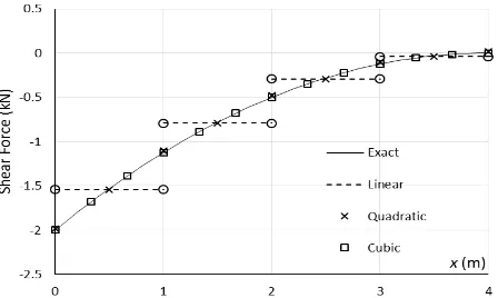
To further assess the accuracy of the DSG beam elements, the profiles of deflection, rotation, bending moment, and shear force obtained using four elements were plotted in Figures 7-10 together with the corresponding exact profiles. The figures demon-strated the exceptional accuracy of the elements in predicting the deflection, rotation, bending moment, and shear force along the beam. The bending moment and shear force obtained using the linear DSG beam element, however, are only exact at the element midpoints. This is because the resulting moment and shear force distributions are, as expected, piecewise linear. It is worth mentioning here that if we use the beam elements with full and selective reduced integrations, the resulting shear force will be very inaccurate [20]. Thus, Figure 10 again demonstrates the superiority of the DSG technique in predicting the shear force distribution.
b h
L q
3 4 5 6 7 8 2
1
Figure 7. Deflection Profile Obtained using Four Linear, Quadratic, and Cubic DSG Beam Elements
Figure 8. Rotation Profile Obtained using Four Linear, Quadratic, and Cubic DSG Beam Elements
Figure 9. Bending Moment Profile Obtained using Four Linear, Quadratic, and Cubic DSG Beam Elements
Figure 10. Shear Force Profile Obtained using Four Linear, Quadratic, and Cubic DSG Beam Elements
Table 6. Normalized Free-end Deflections, Fixed-end Bending Moments, and Fixed-end Shear Forces of the Cantilever Beam for Different Number of Elements, Nel, Obtained using Different Beam Elements
(a) Normalized Results using Linear Beam Elements
Nel Deflection Bending Moment Shear Force
DSG SRI Full DSG SRI Full DSG SRI Full
1 1.245 1.245 0.075 0.500 0.500 0.023 0.333 21.248 1.288
2 1.092 1.092 0.192 0.563 0.563 0.090 0.583 12.348 2.472
4 1.025 1.025 0.455 0.711 0.711 0.308 0.771 8.205 3.993
8 1.006 1.006 0.763 0.835 0.835 0.629 0.880 5.246 4.171
(b) Normalized Results using Quadratic Beam Elements
Nel Deflection Bending Moment Shear Force
DSG SRI Full DSG SRI Full DSG SRI Full
1 1.041 1.041 0.711 0.750 0.750 0.346 0.833 7.805 2.178
2 1.003 1.003 0.950 0.906 0.906 0.683 0.958 4.008 2.449
4 1.000 1.000 0.995 0.973 0.973 0.913 0.990 1.997 1.788
8 1.000 1.000 1.000 0.993 0.993 0.983 0.997 1.285 1.267
(c) Normalized Results using Cubic Beam Elements
Nel Deflection Bending Moment Shear Force
DSG SRI Full DSG SRI Full DSG SRI Full
1
All results are exact.
0.978 0.950 0.790
Exact
3.092 1.749
2 1.004 0.994 0.965 1.392 1.271
4 1.002 0.999 0.996 1.057 1.051
Conclusions
The DSG technique has been applied to the linear, quadratic, and cubic Timoshenko beam elements. The essence of this technique is to replace the troublesome displacement-based shear strain field with a substitute shear strain field obtained from the derivative of the interpolated shear gap. The numerical test results showed that the beam elements with the DSG technique pass the pure bending test, work perfectly in eliminating the shear locking, and can give exceptionally accurate solutions. The distinctive advantage of the DSG technique over the classical SRI is that with the DSG technique a beam element can produce a very accurate shear force distribution, while the with the SRI the shear force distribution will be erroneous. The successful application of the DSG technique in the present beam elements may partly explain the reason of its success in formulating locking-free shell elements [11]. Future research may be directed to application of the DSG technique to curve beam elements and geometrically nonlinear analysis of beams.
References
1. Zienkiewicz, O.C. and Taylor, R.L., The Finite Element Method, Volume 2: Solid Mechanics, Fifth edition, Butterworth-Heinemann, Oxford, 2000.
2. Zienkiewicz, O.C., Taylor, R.L., and Too, J.M., Reduced Integration Technique in General Analysis of Plates and Shells, International Journal of Numerical Methods in Engineering, John Wiley & Sons, 3(2), 1971, pp. 275–290. 3. Hughes, T.J.R., Taylor, R.L., and
Kanok-Nukulchai, W., A Simple and Efficient Finite Element for Plate Bending, International Journal of Numerical Methods in Engineering, John Wiley & Sons, 11(10), 1977, pp. 1529– 1543.
4. Batoz, J.L., Bathe, K., and Ho, L.W., A Study of Three-Node Triangular Plate Bending Elements, International Journal of Numerical Methods in Engineering, John Wiley & Sons, 15(12), 1980, pp. 1771–1812.
5. Ma, H., Development of a Geometrically Non-linear Shell Element by Assumed Strain Methods, Doctoral Dissertation, Asian Institute of Technology, Pathumthani, Thailand, 1990. 6. Mitaim, S., A Family of Triangular Plate
Elements Based on the Assumed Strain Method, Master Thesis, Asian Institute of Technology, Pathumthani, Thailand, 1994.
7. Batoz, J.L. and Katili, I., On a Simple Triangu-lar Reissner/Mindlin Plate Element Based on Incompatible Modes and Discrete Constraints,
International Journal of Numerical Methods in Engineering, John Wiley & Sons, 35(8), 1992, pp. 1603–1632.
8. Katili, I., A New Discrete Kirchhoff-Mindlin Element Based on Mindlin-Reissner Plate Theory and Assumed Shear Strain Fields- Part I: An Extended DKT Element for Thick-Plate Bending Analysis, John Wiley & Sons, Inter-national Journal of Numerical Methods in Engineering, 36(11), 1993, pp. 1859–1883. 9. Katili, I., A New Discrete Kirchhoff-Mindlin
Ele-ment based on Mindlin-Reissner Plate Theory and Assumed Shear Strain Fields- Part II: an Extended DKQ Element for Thick-Plate Bending Analysis, International Journal of Numerical Methods in Engineering, John Wiley & Sons, 36(11), 1993, pp. 1885–1908.
10. Bathe, K.J., Finite Element Procedures, Prentice-Hall, New Jersey, 1996.
11. Bletzinger, K.U., Bischoff, M., and Ramm, E., A Unified Approach for Shear-Locking-Free Triangular and Rectangular Shell Finite Elements, Computers and Structures, Elsevier, 75(3), 2000, pp. 321–334.
12. Koschnick, F., Bischoff, M., Camprubí, N., and Bletzinger, K.U., The Discrete Strain Gap Method and Membrane Locking, Computer Methods in Applied Mechanics and Engineering, Elsevier, 194(21-24), 2005, pp. 2444–2463. 13. Nguyen-Xuan, H., Liu, G.R., Thai-Hoang, C.,
and Nguyen-Thoi, T., An Edge-based Smoothed Finite Element Method (ES-FEM) with Stabi-lized Discrete Shear Gap Technique for Analysis of Reissner–Mindlin Plates, Computer Methods in Applied Mechanics and Engineering, Else-vier, 199(9–12), 2010, pp. 471–489.
14. Nguyen-Xuan, H., Rabczuk, T., Nguyen-Thanh, N., Nguyen-Thoi, T., and Bordas, S., A Node-based Smoothed Finite Element Method with Stabilized Discrete Shear Gap Technique for Analysis of Reissner–Mindlin Plates, Compu-tational Mechanics, Springer, 46(5), 2010, pp. 679–701.
15. Nguyen-Thoi, T., Phung-Van, P., Luong-Van, H., Nguyen-Van, H., and Nguyen-Xuan, H., A Cell-based Smoothed Three-node Mindlin Plate Element (CS-MIN3) for Static and Free Vibration Analyses of Plates, Computational Mechanics, Springer, 51(1), 2012 pp. 65–81. 16. Wong, F.T. and Kanok-Nukulchai, W.,
Kriging-based Finite Element Method: Element-by-element Kriging Interpolation, Civil Engineer-ing Dimension, Petra Christian University, 11(1), 2009, pp. 15-22.
Mechanics and the 6th Asia-Pacific Congress on Computational Mechanics, Seoul, Korea, July 24-29, 2016, pp. 187-206.
18. Cowper, G.R., The Shear Coefficient in
Timo-shenko‟s Beam Theory, Journal of Applied Mechanics, ASME, 33(2), 1966, pp. 335–340. 19. Cook, R.D., Malkus, D.S., Plesha, M.E., and
Witt, R.J., Concepts and Applications of Finite Element Analysis, Fourth edition, John Wiley and Sons, New York, 2002.
20. Prathap, G. The Finite Element Method in Structural Mechanics, Springer, 1993, retrieved from http://www.springer.com/gp/book/9780792-324928 [Accessed: 25-Feb-2016].
21. Chapman, S.J., Matlab Programming for Engineers, Second edition, Brooks/Cole, Pacific Grove, California, 2002.