monographs and handbooks. It sets out to provide students, researchers and nonspecialists alike with a sure grounding in current knowledge, together with comprehensible access to the latest developments in computer communications and networking.
Emphasis is placed on clear and explanatory styles that support a tutorial approach so that even the most complex of topics is presented in a lucid and intelligible manner.
Joseph Migga Kizza
A Guide to Computer
Network Security
CCN Series ISSN 1617-7975
ISBN 978-1-84800-916-5 e-ISBN 978-1-84800-917-2 DOI 10.1007/978-1-84800-917-2
Library of Congress Control Number: 2008942999
© Springer-Verlag London Limited 2009
All rights reserved. This work may not be translated or copied in whole or in part without the written permission of the publisher (Springer Science +Business Media, LLC, 233 Spring Street, New York, NY 10013, USA), except for brief excerpts in connection with reviews or scholarly analysis. Use in connec-tion with any form of informaconnec-tion storage and retrieval, electronic adaptaconnec-tion, computer software, or by similar or dissimilar methodology now known or hereafter developed is forbidden.
The use in this publication of trade names, trademarks, service marks and similar terms, even if they are not identifi ed as such, is not to be taken as an expression of opinion as to whether or not they are subject to proprietary rights.
Printed on acid-free paper
springer.com
University of Tennessee-Chattanooga Department of Computer Science 615 McCallie Ave.
Chattanooga TN 37403 326 Grote Hall USA
Series Editor
Professor A.J. Sammes, BSc, MPhil, PhD, FBCS, CEng CISM Group, Cranfi eld University,
vii If we are to believe in Moore’s law, then every passing day brings new and advanced changes to the technology arena. We are as amazed by miniaturization of computing devices as we are amused by their speed of computation. Everything seems to be in fl ux and moving fast. We are also fast moving towards ubiquitous computing. To achieve this kind of computing landscape, new ease and seamless computing user interfaces have to be developed. Believe me, if you mature and have ever program any digital device, you are, like me, looking forward to this brave new computing landscape with anticipation.
However, if history is any guide to use, we in information security, and indeed every computing device user young and old, must brace themselves for a future full of problems. As we enter into this world of fast, small and concealable ubiquitous computing devices, we are entering fertile territory for dubious, mischievous, and malicious people. We need to be on guard because, as expected, help will be slow coming because fi rst, well trained and experienced personnel will still be diffi cult to get and those that will be found will likely be very expensive as the case is today. Secondly, the security protocols and best practices will, as it is today, keep chang-ing at a fi rst rate which may warrant network administrators to constantly changchang-ing them. Thirdly, as the case is today, it will be extremely diffi cult to keep abreast of the many new vulnerabilities and patches to them. In other words, the computing landscape will change for sure on one side and remain the same on the other.
For these reasons, we need to remain vigilant with better, if not advanced com-puter and information security protocols and best practices because the frequency of computer network attacks and the vulnerability of computer network systems will likely not abet, rather they are likely to increase as before.
More efforts in developing adaptive and scalable security protocols and best practices and massive awareness, therefore, are needed to meet this growing chal-lenge and bring the public to a level where they can be active and safe participants in the brave new worlds of computing.
security is likely to be a major issues. It is intended to bring massive education and awareness of security issues and concerns in cyberspace in general and the com-puting world in particular, their benefi ts to society, the security problems and the dangers likely to be encountered by the users, and be a pathfi nder as it initiates a dialog towards developing better algorithms, protocols, and best practices that will enhance security of computing systems in the anticipated brave new world. It does this comprehensively in four parts and twenty-two chapters. Part I gives the reader an understanding of the working of and the security situation of computer networks. Part II builds on this knowledge and exposes the reader to the prevailing security situ-ation based on a constant security threat. It surveys several security threats. Part III, the largest, forms the core of the guide and presents to the reader most of the best practices and solutions that are currently in use. Part IV is for projects. In addition to the algorithms, protocols, and solutions, several products and services are given for each security item under discussion.
In summary, the guide attempts to achieve the following objectives:
1 Educate the public about cyberspace security in general terms and computer systems security in particular, with reference to the Internet,
2 Alert the public to the magnitude of computer network vulnerabilities, weaknesses, and loopholes inherent in the computer network infrastructure 3 Bring to the public attention effective security solutions and best practice, expert
opinions on those solutions, and the possibility of ad-hoc solutions
4 Look at the roles legislation, regulation, and enforcement play in computer network security efforts
5 Finally, initiate a debate on developing effective and comprehensive algorithms, protocols, and best practices for information security.
Since the guide covers a wide variety of security topics, algorithms, solutions, and best practices, it is intended to be both a teaching and a reference tool for all interested in learning about computer network security issues and available tech-niques to prevent information systems attacks. The depth and thorough discussion and analysis of most of the computer network security issues, together with the discussion of security algorithms, and solutions given, makes the guide a unique reference source of ideas for computer network security personnel, network secu-rity policy makers, and those reading for leisure. In addition, the guide provokes the reader by raising valid legislative, legal, social, and ethical security issues, includ-ing the increasinclud-ingly diminishinclud-ing line between individual privacy and the need for collective and individual security.
The guide targets college students in computer science, information science, technology studies, library sciences, engineering, and to a lesser extent students in the arts and sciences who are interested in information technology. In addition, stu-dents in information management sciences will fi nd the guide particularly helpful. Practitioners, especially those working in information-intensive areas, will likewise fi nd the guide a good reference source. It will also be valuable to those interested in any aspect of information security and assurance and those simply wanting to become cyberspace literates.
Book Resources
There are two types of exercises at the end of chapter: easy and quickly work-able exercises whose responses can be easily spotted from the proceeding text; and more though provoking advanced exercises whole responses may require research outside the content of this book. Also chapter 22 is devoted to lab exercises. There are three types of lab exercises: weekly or bi-weekly assignments that can be done easily with either reading or using readily available software and hardware tools; slightly harder semester long projects that may require extensive time, collabora-tion, and some research to fi nish them successfully; and hard open research projects that require a lot of thinking, take a lot of time, and require extensive research.
We have tried as much as possible, throughout the guide, to use open source software tools. This has two consequences to it: one, it makes the guide affordable keeping in mind the escalating proprietary software prices; and two, it makes the content and related software tools last longer because the content and corresponding exercises and labs are not based on one particular proprietary software tool that can go out anytime.
Instructor Support Materials
As you consider using this book, you may need to know that we have developed materials to help you with your course. The help materials for both instructors and students cover the following areas:
Syllabus. There is a suggested syllabus for the instructor. •
Instructor PowerPoint slides. These are detailed enough to help the instructor, •
especially those teaching the course for the fi rst time. Answers to selected exercises at the end of each chapter •
Laboratory. Since network security is a hands-on course, students need to spend a •
considerable amount of time on scheduled laboratory exercises. The last chapter of the book contains several laboratory exercises and projects. The book resource center contains several more and updates
Instructor manual. These will guide the instructor in the day to day job of getting •
materials ready for the class.
Student laboratory materials. Under this section, we will be continuously posting •
the latest laboratory exercises, software, and challenge projects. These materials can be found at the publisher’s website at
http://www.springeronline.com and at the author’s site at http://www.utc.edu/ Faculty/Joseph-Kizza/
Chattanooga, Tennessee, USA Joseph Migga Kizza
xi
Contents
Part I Understanding Computer Network Security
1 Computer Network Fundamentals ...3
1.1 Introduction ...3
1.2 Computer Network Models ...4
1.3 Computer Network Types ... 5
1.3.1 Local Area Networks (LANs) ... 5
1.3.2 Wide Area Networks (WANs) ...6
1.3.3 Metropolitan Area Networks (MANs) ...6
1.4 Data Communication Media Technology... 7
1.4.1 Transmission Technology ... 7
1.4.2 Transmission Media ...10
1.5 Network Topology ...13
1.5.1 Mesh ...13
1.5.2 Tree ...13
1.5.3 Bus ...14
1.5.4 Star ... 15
1.5.5 Ring ... 15
1.6 Network Connectivity and Protocols ...16
1.6.1 Open System Interconnection (OSI) Protocol Suite ...18
1.6.2 Transport Control Protocol/Internet Protocol (TCP/IP) Model ...19
1.7 Network Services ...22
1.7.1 Connection Services ...22
1.7.2 Network Switching Services ...24
1.8 Network Connecting Devices...26
1.8.1 LAN Connecting Devices ...26
1.8.2 Internetworking Devices ...30
1.9 Network Technologies ...34
1.9.1 LAN Technologies ... 35
1.9.2 WAN Technologies ... 37
1.9.3 Wireless LANs ...39
Exercises ...40
Advanced Exercises ... 41
References ... 41
2 Understanding Computer Network Security ...43
2.1 Introduction ...43
2.1.1 Computer Security ...44
2.1.2 Network Security ... 45
2.1.3 Information Security ... 45
2.2 Securing the Computer Network ... 45
2.2.1 Hardware ...46
2.2.2 Software ...46
2.3 Forms of Protection...46
2.3.1 Access Control ...46
2.3.2 Authentication ...48
2.3.3 Confi dentiality ...48
2.3.4 Integrity ...49
2.3.5 Nonrepudiation ...49
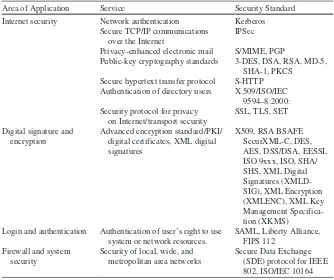
2.4 Security Standards ...50
2.4.1 Security Standards Based on Type of Service/Industry ... 51
2.4.2 Security Standards Based on Size/Implementation ...54
2.4.3 Security Standards Based on Interests ... 55
2.4.4 Best Practices in Security ...56
Exercises ...58
Advanced Exercises ...58
References ...59
Part II Security Challenges to Computer Networks 3 Security Threats to Computer Networks ...63
3.1 Introduction ...63
3.2 Sources of Security Threats ...64
3.2.1 Design Philosophy ... 65
3.2.2 Weaknesses in Network Infrastructure and Communication Protocols ... 65
3.2.3 Rapid Growth of Cyberspace ...68
3.2.4 The Growth of the Hacker Community ...69
3.2.5 Vulnerability in Operating System Protocol ...78
3.2.7 Social Engineering ...79
3.2.8 Physical Theft ...80
3.3 Security Threat Motives ...80
3.3.1 Terrorism ...80
3.3.2 Military Espionage ... 81
3.3.3 Economic Espionage ... 81
3.3.4 Targeting the National Information Infrastructure ...82
3.3.5 Vendetta/Revenge ...82
3.3.6 Hate (National Origin, Gender, and Race) ...83
3.3.7 Notoriety ...83
3.3.8 Greed ...83
3.3.9 Ignorance ...83
3.4 Security Threat Management ...83
3.4.1 Risk Assessment ...84
3.4.2 Forensic Analysis ...84
3.5 Security Threat Correlation ...84
3.5.1 Threat Information Quality ... 85
3.6 Security Threat Awareness ... 85
Exercises ...86
Advanced Exercises ... 87
References ...88
4 Computer Network Vulnerabilities ...89
4.1 Defi nition ...89
4.2 Sources of Vulnerabilities ...89
4.2.1 Design Flaws ...90
4.2.2 Poor Security Management ...93
4.2.3 Incorrect Implementation ...94
4.2.4 Internet Technology Vulnerability ... 95
4.2.5 Changing Nature of Hacker Technologies and Activities ...99
4.2.6 Diffi culty of Fixing Vulnerable Systems ...100
4.2.7 Limits of Effectiveness of Reactive Solutions ... 101
4.2.8 Social Engineering ...102
4.3 Vulnerability Assessment ...103
4.3.1 Vulnerability Assessment Services ...104
4.3.2 Advantages of Vulnerability Assessment Services ... 105
Exercises ... 105
Advanced Exercises ...106
References ...106
5 Cyber Crimes and Hackers ... 107
5.1 Introduction ... 107
5.2 Cyber Crimes ...108
5.2.1 Ways of Executing Cyber Crimes ...108
5.2.2 Cyber Criminals ... 111
5.3 Hackers ... 112
5.3.1 History of Hacking ... 112
5.3.2 Types of Hackers ... 115
5.3.3 Hacker Motives ... 118
5.3.4 Hacking Topologies ... 121
5.3.5 Hackers’ Tools of System Exploitation ...126
5.3.6 Types of Attacks ...128
5.4 Dealing with the Rising Tide of Cyber Crimes ...129
5.4.1 Prevention ...129
5.4.2 Detection ...130
5.4.3 Recovery ...130
5.5 Conclusion ...130
Exercises ... 131
Advanced Exercises ... 131
References ... 131
6 Hostile Scripts ...133
6.1 Introduction ...133
6.2 Introduction to the Common Gateway Interface (CGI) ...133
6.3 CGI Scripts in a Three-Way Handshake ...134
6.4 Server–CGI Interface ...136
6.5 CGI Script Security Issues ... 137
6.6 Web Script Security Issues ...138
6.7 Dealing with the Script Security Problems ...139
6.8 Scripting Languages ...139
6.8.1 Server-Side Scripting Languages ...139
6.8.2 Client-Side Scripting Languages ... 141
Exercises ...143
Advanced Exercises ...143
References ...143
7 Security Assessment, Analysis, and Assurance ... 145
7.1 Introduction ... 145
Contents xv
7.3 Building a Security Policy ...149
7.3.1 Security Policy Access Rights Matrix ...149
7.3.2 Policy and Procedures ... 151
7.4 Security Requirements Specifi cation ... 155
7.5 Threat Identifi cation ...156
7.5.1 Human Factors ...156
7.5.2 Natural Disasters ... 157
7.5.3 Infrastructure Failures ... 157
7.6 Threat Analysis ...159
7.6.1 Approaches to Security Threat Analysis...160
7.7 Vulnerability Identifi cation and Assessment ... 161
7.7.1 Hardware ... 161
7.7.2 Software ...162
7.7.3 Humanware ...163
7.7.4 Policies, Procedures, and Practices ...163
7.8 Security Certifi cation ... 165
7.8.1 Phases of a Certifi cation Process ... 165
7.8.2 Benefi ts of Security Certifi cation ...166
7.9 Security Monitoring and Auditing ...166
7.9.1 Monitoring Tools ...166
7.9.2 Type of Data Gathered ... 167
7.9.3 Analyzed Information ... 167
7.9.4 Auditing ...168
7.10 Products and Services ...168
Exercises ...168
Advanced Exercises ...169
References ...169
Additional References ...169
Part III Dealing with Network Security Challenges 8 Disaster Management ...173
8.1 Introduction ...173
8.1.1 Categories of Disasters ...174
8.2 Disaster Prevention ... 175
8.3 Disaster Response ... 177
8.4 Disaster Recovery ... 177
8.4.1 Planning for a Disaster Recovery ...178
8.4.2 Procedures of Recovery ...179
8.5.1 Always Be Ready for a Disaster ...182
8.5.2 Always Backup Media ...182
8.5.3 Risk Assessment ...182
8.6 Resources for Disaster Planning and Recovery ...182
8.6.1 Local Disaster Resources ...183
Exercises ...183
Advanced Exercises – Case Studies ...183
References ...184
9 Access Control and Authorization ... 185
9.1 Defi nitions ... 185
9.2 Access Rights ... 185
9.2.1 Access Control Techniques and Technologies ... 187
9.3 Access Control Systems ...192
9.3.1 Physical Access Control ...192
9.3.2 Access Cards ...192
9.3.3 Electronic Surveillance ...193
9.3.4 Biometrics ...194
9.3.5 Event Monitoring ... 197
9.4 Authorization ... 197
9.4.1 Authorization Mechanisms ...198
9.5 Types of Authorization Systems ...199
9.5.1 Centralized ...199
9.5.2 Decentralized ...200
9.5.3 Implicit ...200
9.5.4 Explicit ... 201
9.6 Authorization Principles ... 201
9.6.1 Least Privileges ... 201
9.6.2 Separation of Duties ... 201
9.7 Authorization Granularity ...202
9.7.1 Fine Grain Authorization ...202
9.7.2 Coarse Grain Authorization ...202
9.8 Web Access and Authorization ...203
Exercises ...203
Advanced Exercises ...204
Contents xvii
10 Authentication ... 207
10.1 Defi nition ... 207
10.2 Multiple Factors and Effectiveness of Authentication ...208
10.3 Authentication Elements ...210
10.3.1 Person or Group Seeking Authentication ...210
10.3.2 Distinguishing Characteristics for Authentication ...210
10.3.3 The Authenticator ... 211
10.3.4 The Authentication Mechanism ... 211
10.3.5 Access Control Mechanism ...212
10.4 Types of Authentication...212
10.4.1 Nonrepudiable Authentication ...212
10.4.2 Repudiable Authentication ...213
10.5 Authentication Methods ...213
10.5.1 Password Authentication ...214
10.5.2 Public-Key Authentication ...216
10.5.3 Remote Authentication ...220
10.5.4 Anonymous Authentication ...222
10.5.5 Digital Signature-Based Authentication ...222
10.5.6 Wireless Authentication ...223
10.6 Developing an Authentication Policy ...223
Exercises ...224
Advanced Exercises ... 225
References ... 225
11 Cryptography ... 227
11.1 Defi nition ... 227
11.1.1 Block Ciphers ...229
11.2 Symmetric Encryption ...230
11.2.1 Symmetric Encryption Algorithms ... 231
11.2.2 Problems with Symmetric Encryption ...233
11.3 Public Key Encryption ...233
11.3.1 Public Key Encryption Algorithms ...236
11.3.2 Problems with Public Key Encryption ...236
11.3.3 Public Key Encryption Services ...236
11.4 Enhancing Security: Combining Symmetric and Public Key Encryptions ... 237
11.5 Key Management: Generation, Transportation, and Distribution ... 237
11.5.1 The Key Exchange Problem ... 237
11.5.2 Key Distribution Centers (KDCs) ...238
11.5.3 Public Key Management ...240
11.6 Public Key Infrastructure (PKI) ...243
11.6.1 Certifi cates ...244
11.6.2 Certifi cate Authority ...244
11.6.3 Registration Authority (RA) ...244
11.6.4 Lightweight Directory Access Protocols (LDAP) ...244
11.6.5 Role of Cryptography in Communication ... 245
11.7 Hash Function ... 245
11.8 Digital Signatures ...246
Exercises ... 247
Advanced Exercises ...248
References ...248
12 Firewalls ...249
12.1 Defi nition ...249
12.2 Types of Firewalls ...252
12.2.1 Packet Inspection Firewalls ...253
12.2.2 Application Proxy Server: Filtering Based on Known Services ... 257
12.2.3 Virtual Private Network (VPN) Firewalls ... 261
12.2.4 Small Offi ce or Home (SOHO) Firewalls ...262
12.3 Confi guration and Implementation of a Firewall ...263
12.4 The Demilitarized Zone (DMZ) ...264
12.4.1 Scalability and Increasing Security in a DMZ ...266
12.5 Improving Security Through the Firewall ... 267
12.6 Firewall Forensics ...268
12.7 Firewall Services and Limitations ...269
12.7.1 Firewall Services ...269
12.7.2 Limitations of Firewalls ...269
Exercises ...270
Advanced Exercises ...270
References ... 271
13 System Intrusion Detection and Prevention ...273
13.1 Defi nition ...273
13.2 Intrusion Detection ...273
13.2.1 The System Intrusion Process ...274
Contents xix
13.3 Intrusion Detection Systems (IDSs) ...276
13.3.1 Anomaly Detection ... 277
13.3.2 Misuse Detection ...279
13.4 Types of Intrusion Detection Systems ...279
13.4.1 Network-Based Intrusion Detection Systems (NIDSs) ...280
13.4.2 Host-Based Intrusion Detection Systems (HIDSs) ... 285
13.4.3 The Hybrid Intrusion Detection System ... 287
13.5 The Changing Nature of IDS Tools ... 287
13.6 Other Types of Intrusion Detection Systems ...288
13.6.1 System Integrity Verifi ers (SIVs) ...288
13.6.2 Log File Monitors (LFM) ...288
13.6.3 Honeypots...288
13.7 Response to System Intrusion ...290
13.7.1 Incident Response Team ...290
13.7.2 IDS Logs as Evidence ... 291
13.8 Challenges to Intrusion Detection Systems ... 291
13.8.1 Deploying IDS in Switched Environments ...292
13.9 Implementing an Intrusion Detection System ...292
13.10 Intrusion Prevention Systems (IPSs) ...293
13.10.1 Network-Based Intrusion Prevention Systems (NIPSs) ...293
13.10.2 Host-Based Intrusion Prevention Systems (HIPSs) ... 295
13.11 Intrusion Detection Tools ... 295
Exercises ... 297
Advanced Exercises ... 297
References ...298
14 Computer and Network Forensics ...299
14.1 Defi nition ...299
14.2 Computer Forensics ...300
14.2.1 History of Computer Forensics ... 301
14.2.2 Elements of Computer Forensics ...302
14.2.3 Investigative Procedures ...303
14.2.4 Analysis of Evidence ...309
14.3 Network Forensics ... 315
14.3.1 Intrusion Analysis ...316
14.3.2 Damage Assessment ... 321
14.4 Forensics Tools ... 321
14.4.1 Computer Forensic Tools ...322
14.4.2 Network Forensic Tools ...326
Advanced Exercises ...328
References ...328
15 Virus and Content Filtering ... 331
15.1 Defi nition ... 331
15.2 Scanning, Filtering, and Blocking ... 331
15.2.1 Content Scanning ...332
15.2.2 Inclusion Filtering ...332
15.2.3 Exclusion Filtering ...333
15.2.4 Other Types of Content Filtering ...333
15.2.5 Location of Content Filters ... 335
15.3 Virus Filtering ...336
15.3.1 Viruses ...336
15.4 Content Filtering ...344
15.4.1 Application Level Filtering ...344
15.4.2 Packet-Level Filtering and Blocking ...346
15.4.3 Filtered Material ... 347
15.5 Spam ...348
Exercises ...350
Advanced Exercises ...350
References ...350
16 Standardization and Security Criteria: Security Evaluation of Computer Products ... 351
16.1 Introduction ... 351
16.2 Product Standardization ...352
16.2.1 Need for the Standardization of (Security) Products ...352
16.2.2 Common Computer Product Standards ...353
16.3 Security Evaluations ...354
16.3.1 Purpose of Evaluation ...354
16.3.2 Security Evaluation Criteria ...354
16.3.3 Basic Elements of an Evaluation ... 355
16.3.4 Outcomes/Benefi ts ... 355
16.4 Major Security Evaluation Criteria ... 357
16.4.1 Common Criteria (CC) ... 357
16.4.2 FIPS...358
Contents xxi
16.4.4 Information Technology Security Evaluation
Criteria (ITSEC) ... 361
16.4.5 The Trusted Network Interpretation (TNI): The Red Book ... 361
16.5 Does Evaluation Mean Security? ...362
Exercises ...362
Advanced Exercises ...363
References ...363
17 Computer Network Security Protocols ... 365
17.1 Introduction ... 365
17.2 Application Level Security ...366
17.2.1 Pretty Good Privacy (PGP) ...368
17.2.2 Secure/Multipurpose Internet Mail Extension (S/MIME) ...368
17.2.3 Secure-HTTP (S-HTTP) ...369
17.2.4 Hypertext Transfer Protocol over Secure Socket Layer (HTTPS) ...373
17.2.5 Secure Electronic Transactions (SET) ...373
17.2.6 Kerberos ... 375
17.3 Security in the Transport Layer ...378
17.3.1 Secure Socket Layer (SSL) ...378
17.3.2 Transport Layer Security (TLS) ...382
17.4 Security in the Network Layer ...382
17.4.1 Internet Protocol Security (IPSec) ...382
17.4.2 Virtual Private Networks (VPN) ... 387
17.5 Security in the Link Layer and over LANS ... 391
17.5.1 Point-to-Point Protocol (PPP) ... 391
17.5.2 Remote Authentication Dial-In User Service (RADIUS) ...392
17.5.3 Terminal Access Controller Access Control System (TACACS + ) ...394
Exercises ...394
Advanced Exercises ... 395
18 Security in Wireless Networks and Devices ... 397
18.1 Introduction ... 397
18.2 Cellular Wireless Communication Network Infrastructure ... 397
18.2.1 Development of Cellular Technology ...400
18.2.2 Limited and Fixed Wireless Communication Networks ...404
18.3 Wireless LAN (WLAN) or Wireless Fidelity (Wi-Fi) ...406
18.3.1 WLAN (Wi-Fi) Technology ...406
18.3.2 Mobile IP and Wireless Application Protocol (WAP) ... 407
18.4 Standards for Wireless Networks ...410
18.4.1 The IEEE 802.11 ...410
18.4.2 Bluetooth ... 411
18.5 Security in Wireless Networks ...413
18.5.1 WLANs Security Concerns ...413
18.5.2 Best Practices for Wi-Fi Security ...419
18.5.3 Hope on the Horizon for WEP ...420
Exercises ...420
Advanced Exercises ... 421
References ...422
19 Security in Sensor Networks ...423
19.1 Introduction ...423
19.2 The Growth of Sensor Networks ...424
19.3 Design Factors in Sensor Networks ... 425
19.3.1 Routing ... 425
19.3.2 Power Consumption ...428
19.3.3 Fault Tolerance ...428
19.3.4 Scalability ...428
19.3.5 Product Costs ...428
19.3.6 Nature of Hardware Deployed ...428
19.3.7 Topology of Sensor Networks ...429
19.3.8 Transmission Media ...429
19.4 Security in Sensor Networks ...429
19.4.1 Security Challenges ...429
19.4.2 Sensor Network Vulnerabilities and Attacks ... 431
19.4.3 Securing Sensor Networks ...432
Contents xxiii
19.6 Trends in Sensor Network Security Research ...434 19.6.1 Cryptography ... 435 19.6.2 Key Management ... 435 19.6.3 Confi dentiality, Authentication, and Freshness ...436 19.6.4 Resilience to Capture ...436
Exercises ... 437
Advanced Exercises ... 437
References ...438
20 Other Efforts to Secure Information and Computer Networks ...439 20.1 Introduction ...439 20.2 Legislation ...439 20.3 Regulation ...440 20.4 Self-Regulation ...440 20.4.1 Hardware-Based Self-Regulation ... 441 20.4.2 Software-Based Self-Regulation ... 441 20.5 Education ...442 20.5.1 Focused Education ...443 20.5.2 Mass Education ...444 20.6 Reporting Centers ...444 20.7 Market Forces ...444 20.8 Activism ... 445 20.8.1 Advocacy ... 445 20.8.2 Hotlines ...446
Exercises ...446
Advanced Exercises ... 447
References ... 447
21 Security Beyond Computer Networks: Information Assurance ...449 21.1 Introduction ...449 21.2 Collective Security Initiatives and Best Practices ...450 21.2.1 The U.S. National Strategy to Secure Cyberspace...450 21.2.2 Council of Europe Convention on Cyber Crime ...452
Part IV Projects
22 Projects ... 457 22.1 Introduction ... 457 22.2 Part I: Weekly/Biweekly Laboratory Assignments ... 457 22.3 Part II: Semester Projects ... 461 22.3.1 Intrusion Detection Systems ... 461 22.3.2 Scanning Tools for System Vulnerabilities ...464 22.4 The Following Tools Are Used to Enhance Security in Web
Applications ...466 22.4.1 Public Key Infrastructure ...466 22.5 Part III: Research Projects ... 467 22.5.1 Consensus Defense ... 467 22.5.2 Specialized Security ... 467 22.5.3 Protecting an Extended Network ... 467 22.5.4 Automated Vulnerability Reporting ... 467 22.5.5 Turn-Key Product for Network Security Testing ...468 22.5.6 The Role of Local Networks in the Defense of the National
Critical Infrastructure ...468 22.5.7 Enterprise VPN Security ...468 22.5.8 Perimeter Security ...469 22.5.9 Enterprise Security ...469 22.5.10 Password Security – Investigating the Weaknesses ...469
Part I
J.M. Kizza, A Guide to Computer Network Security, Computer Communications and Networks, DOI 10.1007/978-1-84800-917-2_1, © Springer-Verlag London Limited 2009
3
Computer Network Fundamentals
1.1 Introduction
The basic ideas in all types of communication are that there must be three ingre-dients for the communication to be effective. First, there must be two entities, dubbed a sender and a receiver. These two must have something they need to share. Second, there must be a medium through which the sharable item is channeled. This is the transmission medium. Finally, there must be an agreed-on set of com-munication rules or protocols. These three apply to every category or structure of communication.
In this chapter, we will focus on these three components in a computer network. But what is a computer network? A computer network is a distributed system con-sisting of loosely coupled computers and other devices. Any two of these devices, which we will from now on refer to as network elements or transmitting elements without loss of generality, can communicate with each other through a communica-tion medium. In order for these connected devices to be considered a communicat-ing network, there must be a set of communicatcommunicat-ing rules or protocols each device in the network must follow to communicate with another device in the network. The resulting combination consisting of hardware and software is a computer com-munication network or computer network in short. Figure 1.1 shows a computer network.
The hardware component is made of network elements consisting of a collec-tion of nodes that include the end systems commonly called hosts and intermediate switching elements that include hubs, bridges, routers, and gateways that, without loss of generality, we will call network elements.
4 1 Computer Network Fundamentals
and the software may be as different as possible, but the whole combination must work together in unison.
Internetworking technology enables multiple, diverse underlying hardware tech-nologies and different software regimes to interconnect heterogeneous networks and bring them to communicate smoothly. The smooth working of any computer communication network is achieved through the low-level mechanisms provided by the network elements and high-level communication facilities provided by the software running on the communicating elements. Before we discuss the working of these networks, let us first look at the different types of networks.
1.2 Computer Network Models
There are several configuration models that form a computer network. The most common of these are the centralized and distributed models. In a centralized model, several computers and devices are interconnected, and can talk to each other. However, there is only one central computer, called the master, through which all correspondence must take place. Dependent computers, called surro-gates, may have reduced local resources, such as memory, and sharable global resources are controlled by the master at the center. Unlike the centralized model, however, the distributed network consists of loosely coupled comput-ers interconnected by a communication network consisting of connecting ele-ments and communication channels. The computers themselves may own their resources locally or may request resources from a remote computer. These com-puters are known by a string of names, including host, client, or node. If a host has resources that other hosts need, then that host is known as a server. Commu-nication and sharing of resources are not controlled by the central computer but are arranged between any two communicating elements in the network. Figures 1.2 and 1.3 show a centralized network model and a distributed network model, respectively.
Fig. 1.1 A Computer Network
Ethernet
Laptop computer Laptop computer Workstation
Laser printer
1.3 Computer Network Types
Computer networks come in different sizes. Each network is a cluster of network elements and their resources. The size of the cluster determines the network type. There are, in general, two main network types: the local area network (LAN) and wide area network (WAN).
1.3.1 Local Area Networks (LANs)
A computer network with two or more computers or clusters of network and their resources connected by a communication medium sharing communication proto-cols and confined in a small geographical area, such as a building floor, a building, Fig. 1.2 A Centralized network model
Surrogate Computer
Surrogate Computer Surrogate Printer
Surrogate Laptop Server/Master
Fig. 1.3 A Distributed network model
Laptop computer
Workstation
Computer
Mac II
6 1 Computer Network Fundamentals
or a few adjacent buildings, is called a local area network (LAN). The advantage of a LAN is that all network elements are close together so the communication links maintain a higher speed of data movement. Also, because of the proximity of the communicating elements, high-cost and high quality communicating elements can be used to deliver better service and high reliability. Figure 1.4 shows a LAN network.
1.3.2 Wide Area Networks (WANs)
A wide area network (WAN), on the other hand, is a network made up of one or more clusters of network elements and their resources but instead of being con-fined to a small area, the elements of the clusters or the clusters themselves are scattered over a wide geographical area as in a region of a country or across the whole country, several countries, or the entire globe like the Internet for example. Some advantages of a WAN include distributing services to a wider community and availability of a wide array of both hardware and software resources that may not be available in a LAN. However, because of the large geographical areas covered by WANs, communication media are slow and often unreliable. Figure 1.5 shows a WAN network.
1.3.3 Metropolitan Area Networks (MANs)
Between the LAN and WAN, there is also a middle network called the metropolitan area network (MAN) because it covers a slightly wider area than the LAN but not so wide as to be considered a WAN. Civic networks that cover a city or part of a city are a good example of a MAN. MANs are rarely talked about because they are quiet often overshadowed by cousin LAN to the left and cousin WAN to the right. Fig. 1.4 A LAN Network
Ethernet IBM compatible Laptop computer
Scanner
Workstation
1.4 Data Communication Media Technology
The performance of a network type depends greatly on the transmission technology and media used in the network. Let us look at these two.
1.4.1 Transmission Technology
The media through which information has to be transmitted determine the signal to be used. Some media permit only analog signals. Some allow both analog and digi-tal. Therefore, depending on the media type involved and other considerations, the input data can be represented as either digital or analog signal. In an analog format, data is sent as continuous electromagnetic waves on an interval representing things such as voice and video and propagated over a variety of media that may include copper wires, twisted coaxial pair or cable, fiber optics, or wireless. We will discuss these media soon. In a digital format, on the other hand, data is sent as a digital signal, a sequence of voltage pulses that can be represented as a stream of binary bits. Both analog and digital data can be propagated and many times represented as either analog or digital.
Transmission itself is the propagation and processing of data signals between network elements. The concept of representation of data for transmission, either as analog or digital signal, is called an encoding scheme. Encoded data is then trans-mitted over a suitable transmission medium that connects all network elements. There are two encoding schemes, analog and digital. Analog encoding propagates analog signals representing analog data such as sound waves and voice data. Digital encoding, on the other hand, propagates digital signals representing either an analog or a digital signal representing digital data of binary streams by two voltage levels. Fig. 1.5 A WAN Network
Server
Computer Laptop
Laptop Router Router
Laptop
Printer Internet
8 1 Computer Network Fundamentals
Since our interest in this book is in digital networks, we will focus on the encoding of digital data.
1.4.1.1 Analog Encoding of Digital Data
Recall that digital information is in the form of 1s or 0s. To send this information over some analog medium such as the telephone line, for example, which has lim-ited bandwidth, digital data needs to be encoded using modulation and demodula-tion to produce analog signals. The encoding uses a continuous oscillating wave, usually a sine wave, with a constant frequency signal called a carrier signal. The carrier has three modulation characteristics: amplitude, frequency, and phase shift. The scheme then uses a modem, a modulation–demodulation pair, to modulate and demodulate the data signal based on any one of the three carrier characteristics or a combination. The resulting wave is between a range of frequencies on both sides of the carrier as shown below [1]:
Amplitude
• modulation represents each binary value by a different amplitude of the carrier frequency. The absence of or low carrier frequency may represent a 0 and any other frequency then represents a 1. But this is a rather inefficient modulation technique and is therefore used only at low frequencies up to 1200 bps in voice grade lines.
Frequency
• modulation also represents the two binary values by two different frequencies close to the frequency of the underlying carrier. Higher frequencies represent a 1 and low frequencies represent a 0. The scheme is less susceptible to errors.
Phase shift
• modulation changes the timing of the carrier wave, shifting the carrier phase to encode the data. A 1 is encoded as a change in phase by 180 degrees and a 0 may be encoded as a 0 change in phase of a carrier signal. This is the most efficient scheme of the three and it can reach a transmission rate of up to 9600 bps.
1.4.1.2 Digital Encoding of Digital Data
other representations such as the Manchester and differential Manchester, which encode clock information along with the data.
One may wonder why go through the hassle of digital encoding and transmis-sion. There are several advantages over its cousin, analog encoding. These include the following:
Plummeting costs of digital circuitry
•
More efficient integration of voice, video, text, and image
•
Reduction of noise and other signal impairment because of use of repeaters
•
Capacity of channels is utilized best with digital techniques
•
Better encryption and hence better security than in analog transmission
•
1.4.1.3 Multiplexing of Transmission Signals
Quite often during the transmission of data over a network medium, the volume of transmitted data may far exceed the capacity of the medium. Whenever this happens, it may be possible to make multiple signal carriers share a transmission medium. This is referred to as multiplexing. There are two ways in which multi-plexing can be achieved: time-division multimulti-plexing (TMD) and frequency-division multiplexing (FDM).
In FDM, all data channels are first converted to analog form. Since a number of signals can be carried on a carrier, each analog signal is then modulated by a separate and different carrier frequency, and this makes it possible to recover dur-ing the demultiplexdur-ing process. The frequencies are then bundled on the carrier. At the receiving end, the demultiplexer can select the desired carrier signal and use it Fig. 1.6 NRZ-L N Nonreturn to zero level representation code
000000000000001111111111000000000000000000011111110000000000000001111111 1
Fig. 1.7 NRZI Nonreturn to zero Invert on ones representation code
10 1 Computer Network Fundamentals
to extract the data signal for that channel in such a way that the bandwidths do not overlap. FDM has an advantage of supporting full-duplex communication.
TDM, on the other hand, works by dividing the channel into time slots that are allocated to the data streams before they are transmitted. At both ends of the trans-mission, if the sender and receiver agree on the time-slot assignments, then the receiver can easily recover and reconstruct the original data streams. So multiple digital signals can be carried on one carrier by interleaving portions of each signal in time.
1.4.2 Transmission Media
As we have observed above, in any form of communication, there must be a medium through which the communication can take place. So network elements in a net-work need a medium in order to communicate. No netnet-work can function without a transmission medium because there would be no connection between the transmit-ting elements. The transmission medium plays a vital role in the performance of the network. In total, characteristic quality, dependability, and overall performance of a network depend heavily on its transmission medium. The transmission medium also determines a network’s capacity in realizing the expected network traffic, reli-ability for the network’s availreli-ability, size of the network in terms of the distance covered, and the transmission rate. Network transmission media can be either wired or wireless.
1.4.2.1 Wired Transmission Media
Wired transmission media are used in fixed networks physically connecting every network element. There are different types of physical media, the most common of which are copper wires, twisted pair, coaxial cables, and optical fibers.
Copper wires have been traditionally used in communication because of their low resistance to electrical currents that allows signals to travel even further. But copper wires suffer interference from electromagnetic energy in the environment, and because of this, they must always be insulated
LANs, twisted pair technology has been abandoned in favor of other technologies. Figure 1.8 shows a twisted pair.
Coaxial cables are dual-conductor cables with a shared inner conductor in the core of the cable protected by an insulation layer and the outer conductor surround-ing the insulation. These cables are called coaxial because they share the inner conductor. The inner core conductor is usually made of solid copper wire, but at times can also be made up of stranded wire. The outer conductor commonly made of braided wires, but sometimes made of metallic foil or both, forms a protective tube around the inner conductor. This outer conductor is also further protected by another outer coating called the sheath. Figure 1.9 shows a coaxial cable. Coaxial cables are commonly used in television transmissions. Unlike twisted pairs, coaxial cables can be used over long distances. There are two types of coaxial cables: thin-net, a light and flexible cabling medium that is inexpensive and easy to install; and the thickent, which is thicker and harder to break and can carry more signals through a longer distance than thinnet.
Optical fiber is a small medium made up of glass and plastics and conducts an optical ray. This is the most ideal cable for data transmission because it can accommodate extremely high bandwidths and has few problems with electromag-netic interference that coaxial cables suffer from. It can also support cabling for several kilometers. The two disadvantages of fiber-optic cables, however, are cost and installation difficulty. As shown in Fig. 1.10, a simple optical fiber has a central core made up of thin fibers of glass or plastics. The fibers are protected by a glass or plastic coating called a cladding. The cladding, though made up of the same materi-als as the core, has different properties that give it the capacity to reflect back the core rays that tangentially hit on it. The cladding itself is encased in a plastic jacket. The jacket protects the inner fiber from external abuses such as bending and abra-sions. Optical fiber cables transmit data signals by first converting them into light signals. The transmitted light is emitted at the source from either a light emitting
Fig. 1.9 Optical Fiber Core
Jacket
Cladding
Fig. 1.8 Coaxial Cable
Inner conductor
Outer sheath
.
12 1 Computer Network Fundamentals
diode (LED) or an injection laser diode (ILD). At the receiving end, the emitted rays are received by a photo detector that converts them back to the original form.
1.4.2.2 Wireless Communication
Wireless communication and wireless networks have evolved as a result of rapid development in communication technologies, computing, and people’s need for mobility. Wireless networks fall in one of the following three categories depending on distance as follows:
Restricted Proximity Network
• : This network involves local area networks
(LANs) with a mixture of fixed and wireless devices. Intermediate/Extended Network:
• This wireless network is actually made up of
two fixed LAN components joined together by a wireless component. The bridge may be connecting LANs in two nearby buildings or even further.
Mobile Network:
• This is a fully wireless network connecting two network elements. One of these elements is usually a mobile unit that connects to the home network (fixed) using cellular or satellite technology.
These three types of wireless networks are connected using basic media such as infrared, laser beam, narrow-band and spread-spectrum radio, microwave, and satellite communication [2].
Infrared: During an infrared transmission, one network element remotely emits and transmits pulses of infrared light that carry coded instructions to the receiving network element. As long as there is no object to stop the transmitted light, the receiver gets the instruction. Infrared is best used effectively in a small confined area, within 100 feet, for example, a television remote communicating with the tele-vision set. In a confined area such as this, infrared is relatively fast and can support high bandwidths of up to 10 Mbps.
High-Frequency Radio: During a radio communication, high-frequency elec-tromagnetic radio waves or radio frequency commonly referred to as RF transmis-sions are generated by the transmitter and are picked up by the receiver. Because the range of radio frequency band is greater than that of infrared, mobile computing elements can communicate over a limited area without both transmitter and receiver being placed along a direct line of sight; the signal can bounce off light walls, build-ings, and atmospheric objects. RF transmissions are very good for long distances when combined with satellites to refract the radio waves.
Microwave: Microwaves are a higher-frequency version of radio waves but whose transmissions, unlike those of the radio, can be focused in a single direction. Microwave transmissions use a pair of parabolic antennas that produce and receive narrow, but highly directional signals. To be sensitive to signals, both the transmit-ting and receiving antennas must focus within a narrow area. Because of this, both the transmitting and receiving antennas must be carefully adjusted to align the trans-mitted signal to the receiver. Microwave communication has two forms: terrestrial, when it is near ground, and satellite microwave. The frequencies and technologies employed by these two forms are similar but with notably distinct differences.
Laser: Laser light can be used to carry data for several thousand yards through air and optical fibers. But this is possible only if there are no obstacles in the line of sight. Lasers can be used in many of the same situations as microwaves, and like microwaves, laser beams must be refracted when used over long distances.
1.5 Network Topology
Computer networks, whether LANs, MANs, or WANs, are constructed based on a topology. The are several topologies including the following popular ones.
1.5.1 Mesh
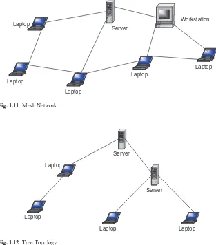
A mesh topology allows multiple access links between network elements, unlike other types of topologies. The multiplicity of access links between the network elements offers an advantage in network reliability because whenever one network element fails, the network does not cease operations; it simply finds a bypass to the failed element and the network continues to function. Mesh topology is most often applied in MAN networks. Figure 1.11 shows a mesh network.
1.5.2 Tree
14 1 Computer Network Fundamentals
1.5.3 Bus
A more popular topology, especially for LANs, is the bus topology. Elements in a net-work using a bus topology always share a bus and, therefore, have equal access to all LAN resources. Every network element has full-duplex connections to the transmit-ting medium which allows every element on the bus to send and receive data. Because each computing element is directly attached to the transmitting medium, a transmis-sion from any one element propagates through the entire length of the medium in either direction and therefore can be received by all elements in the network. Because of this, precautions need to be taken to make sure that transmissions intended for one element can be received by that element and no other element. The network must also use a mechanism that handles disputes in case two or more elements try to transmit at the same time. The mechanism deals with the likely collision of signals and brings a Fig. 1.11 Mesh Network
Laptop
Server
Laptop
Laptop
Laptop Workstation Laptop
Fig. 1.12 Tree Topology
Server
Laptop
Laptop Laptop
quick recovery from such a collision. It is also necessary to create fairness in the net-work so that all other elements can transmit when they need to do so. See Fig. 1.13.
A collision control mechanism must also improve efficiency in the network using a bus topology by allowing only one element in the network to have control of the bus at any one time. This network element is then called the bus master and other elements are considered to be its slaves. This requirement prevents collision from occurring in the network as elements in the network try to seize the bus at the same time. A bus topology is commonly used by LANs.
1.5.4 Star
Another very popular topology, especially in LAN network technologies, is a star topol-ogy. A star topology is characterized by a central prominent node that connects to every other element in the network. So, all the elements in the network are connected to a cen-tral element. Every network element in a star topology is connected pairwise in a point-to-point manner through the central element, and communication between any pair of elements must go through this central element. The central element or node can either operate in a broadcast fashion, in which case information from one element is broadcast to all connected elements, or transmit as a switching device in which the incoming data is transmitted only to one element, the nearest element enroute to the destination. The biggest disadvantage to the star topology in networks is that the failure of the central element results in the failure of the entire network. Figure 1.14 shows a star topology.
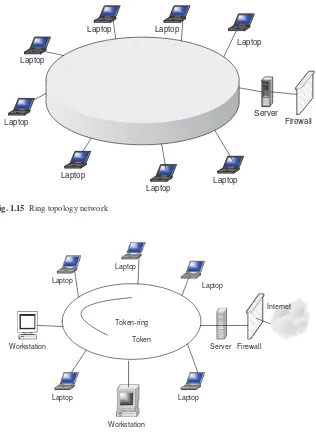
1.5.5 Ring
Finally another popular network topology is the ring topology. In this topology, each computing element in a network using a ring topology is directly connected to Fig. 1.13 Bus topology
Laptop
Laptop
16 1 Computer Network Fundamentals
the transmitting medium via a unidirectional connection so that information put on the transmission medium can reach all computing elements in the network through a mechanism of taking turns in sending information around the ring. Figure 1.15 shows a ring topology network. The taking of turns in passing information is man-aged through a token system. A token is a system-wide piece of information that guarantees the current owner to be the bus master. As long as it owns the token, no other network element is allowed to transmit on the bus. When an element currently sending information and holding the token has finished, it passes the token down-stream to its nearest neighbor. The token system is a good management system of collision and fairness.
There are variants of a ring topology collectively called hub hybrids combining either a star with a bus or a stretched star as shown in Fig. 1.16.
Although network topologies are important in LANs, the choice of a topology depends on a number of other factors, including the type of transmission medium, reliability of the network, the size of the network, and its anticipated future growth. Recently the most popular LAN topologies have been the bus, star, and ring topolo-gies. The most popular bus- and star-based LAN topology is the Ethernet, and the most popular ring-based LAN topology is the token ring.
1.6 Network Connectivity and Protocols
In the early days of computing, computers were used as stand-alone machines, and all work that needed cross-computing was done manually. Files were moved on disks from computer to computer. There was, therefore, a need for cross-computing where more than one computer should talk to others and vice versa.
Fig. 1.14 Star topology
Laptop
Laptop
Laptop
Laptop
Laptop
Laptop Laptop
A new movement was, therefore, born. It was called the open system movement, which called for computer hardware and software manufacturers to come up with a way for this to happen. But to make this possible, standardization of equipment and software was needed. To help in this effort and streamline computer communica-tion, the International Standards Organization (ISO) developed the Open System Interconnection (OSI) model. The OSI is an open architecture model that functions Fig. 1.15 Ring topology network
Laptop
Laptop
Laptop
Laptop Laptop
Laptop Laptop
Server
Firewall Laptop
Fig. 1.16 Token ring hub
Token-ring
Workstation
Laptop
Server Firewall Laptop
Laptop
Workstation
Laptop Token
18 1 Computer Network Fundamentals
as the network communication protocol standard, although it is not the most widely used one. The Transport Control Protocol/Internet Protocol (TCP/IP) model, a rival model to OSI, is the most widely used. Both OSI and TCP/IP models use two proto-col stacks, one at the source element and the other at the destination element
1.6.1 Open System Interconnection (OSI) Protocol Suite
The development of the OSI model was based on the secure premise that a communi-cation task over a network can be broken into seven layers, where each layer represents a different portion of the task. Different layers of the protocol provide different services and ensure that each layer can communicate only with its own neighboring layers. That is, the protocols in each layer are based on the protocols of the previous layers.
Starting from the top of the protocol stack, tasks and information move down from the top layers until they reach the bottom layer where they are sent out over the network media from the source system to the destination. At the destination, the task or information rises back up through the layers until it reaches the top. Each layer is designed to accept work from the layer above it and to pass work down to the layer below it, and vice versa. To ease interlayer communication, the interfaces between the layers are standardized. However, each layer remains independent and can be designed independently and each layer’s functionality should not affect the functionalities of other layers above and below it.
Table 1.1 shows an OSI model consisting of seven layers and the descriptions of the services provided in each layer.
In peer-to-peer communication, the two communicating computers can initiate and receive tasks and data. The task and data initiated from each computer starts from the top in the application layer of the protocol stack on each computer. The tasks and data then move down from the top layers until they reach the bottom layer, where they are sent out over the network media from the source system to the destination. At the destination, the task and data rise back up through the layers until the top. Each layer is designed to accept work from the layer above it and pass work down to the layer below it. As data passes from layer to layer of the sender machine, layer headers are appended to the data, causing the datagram to grow larger. Each layer header contains information for that layer’s peer on the remote system. That information may indicate how to route the packet through the network or what should be done to the packet as it is handed back up the layers on the recipi-ent computer.
1.6.2 Transport Control Protocol/Internet Protocol (TCP/IP)
Model
Among the OSI rivals was the TCP/IP, which was far less complex and more his-torically established by the time the OSI came on the market. The TCP/IP model does not exactly match the OSI model. For example, it has two to three fewer levels than the seven layers of the OSI model. It was developed for the US Department of Defense Advanced Research Project Agency (DARPA); but over the years, it has seen a phenomenal growth in popularity and it is now the de facto standard for the Internet and many intranets. It consists of two major protocols: the transmission control protocol (TCP) and the Internet protocol (IP), hence the TCP/IP designa-tion. Table 1.3 shows the layers and protocols in each layer.
Since TCP/IP is the most widely used in most network protocol suites by the Internet and many intranets, let us focus on its layers here.
Table 1.1 ISO protocol layers and corresponding services Layer Number Protocol
7 Application
6 Presentation
5 Session
4 Transport
3 Network
2 Data Link
1 Physical
Fig. 1.17 ISO logical peer communication model
Application Presentation
Session Transport
Network Datalink
Physical Physical
Datalink Network Transport
Session Presentation
Application
Channel
Machine A Machine B
Table 1.2 OSI datagrams seen in each layer with header added No header Data Application
20 1 Computer Network Fundamentals
1.6.2.1 Application Layer
This layer, very similar to the application layer in the OSI model, provides the user interface with resources rich in application functions. It supports all network appli-cations and includes many protocols on a data structure consisting of bit streams as shown in Fig. 1.18.
1.6.2.2 Transport Layer
This layer, again similar to the OSI model session layer, is a slightly removed from the user and is hidden from the user. Its main purpose is to transport application layer messages that include application layer protocols in their headers between the
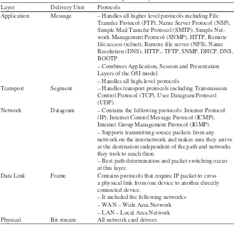
Table 1.3 TCP/IP protocol layers Layer Delivery Unit Protocols
Application Message – Handles all higher level protocols including File Transfer Protocol (FTP), Name Server Protocol (NSP), Simple Mail Transfer Protocol (SMTP), Simple Net-work Management Protocol (SNMP), HTTP, Remote file access (telnet), Remote file server (NFS), Name Resolution (DNS), HTTP,- TFTP, SNMP, DHCP, DNS, BOOTP
– Combines Application, Session and Presentation Layers of the OSI model.
– Handles all high-level protocols
Transport Segment – Handles transport protocols including Transmission Control Protocol (TCP), User Datagram Protocol (UDP).
Network Datagram – Contains the following protocols: Internet Protocol (IP), Internet Control Message Protocol (ICMP), Internet Group Management Protocol (IGMP). – Supports transmitting source packets from any network on the internetwork and makes sure they arrive at the destination independent of the path and networks they took to reach there.
– Best path determination and packet switching occur at this layer.
Data Link Frame Contains protocols that require IP packet to cross a physical link from one device to another directly connected device.
– It included the following networks: – WAN – Wide Area Network – LAN – Local Area Network Physical Bit stream All network card drivers.
Fig. 1.18 Application layer data frame
host and the server. For the Internet network, the transport layer has two standard protocols: transport control protocol (TCP) and user datagram protocol (UDP). TCP provides a connection-oriented service, and it guarantees the delivery of all application layer packets to their destination. This guarantee is based on two mecha-nisms: congestion control that throttles the transmission rate of the source element when there is traffic congestion in the network and the flow control mechanism that tries to match sender and receiver speeds to synchronize the flow rate and reduce the packet drop rate. While TCP offers guarantees of delivery of the application layer packets, UDP, on the other hand, offers no such guarantees. It provides a no-frills connectionless service with just delivery and no acknowledgements. But it is much more efficient and a protocol of choice for real-time data such as streaming video and music. Transport layer delivers transport layer packets and protocols to the network layer. Figure 1.19 shows the TCP data structure, and Fig. 1.20 shows the UDP data structure.
1.6.2.3 Network Layer
This layer moves packets, now called datagrams, from router to router along the path from a source host to the destination host. It supports a number of protocols including the Internet Protocol (IP), Internet Control Message Protocol (ICMP) and Internet Group Management Protocol (IGMP). The IP Protocol is the most widely used network layer protocol. IP uses header information from the transport layer protocols that include datagram source and destination port numbers from IP addresses, and other TCP header and IP information, to move datagrams from router to router through the network. Best routes are found in the network by using routing algorithms. Figure 1.21 shows the IP datagram structure.
The standard IP address has been the so-called IPv4, a 32-bit addressing scheme. But with the rapid growth of the Internet, there was fear of running out of addresses, so IPv6, a new 64-bit addressing scheme, was created. The network layer conveys the network layer protocols to the data link layer.
Fig. 1.19 A TCP data structure 32 bits
Source address Destination address Sequence number Acknowledgement number
Other control information Data
Fig. 1.20 An UDP data structure 32 bits
Source address Destination address Other header control
information
UDP Checksum
22 1 Computer Network Fundamentals
1.6.2.4 Data Link Layer
This layer provides the network with services that move packets from one packet switch like a router to the next over connecting links. This layer also offers reliable delivery of network layer packets over links. It is at the lowest level of communication, and it includes the network interface card (NIC) and operating system (OS) protocols. The protocols in this layer include: Ethernet, asynchronous transfer mode (ATM), and others such as frame relay. The data link layer protocol unit, the frame, may be moved over links from source to destination by different link layer protocols at different links along the way.
1.6.2.5 Physical Layer
This layer is responsible for literally moving data link datagrams bit by bit over the links and between the network elements. The protocols here depend on and use the characteristics of the link medium and the signals on the medium.
1.7 Network Services
For a communication network to work effectively, data in the network must be able to move from one network element to another. This can only happen if the network services to move such data work. For data networks, these services fall into two categories:
Connection services to facilitate the exchange of data between the two network
•
communicating end-systems with as little data loss as possible and in as little time as possible
Switching services to facilitate the movement of data from host to host across
•
the length and width of the network mesh of hosts, hubs, bridges, routers, and gateways
1.7.1 Connection Services
How do we get the network transmitting elements to exchange data over the network? Two types of connection services are used: the connected-oriented and connectionless services.
Fig. 1.21 An IP datagram structure
Other header control information
Source port number
Destination port number
1.7.1.1 Connected-Oriented Services
With a connection-oriented service, before a client can send packets with real data to the server, there must be a three-way handshake. We will define this three-way handshake in later chapters. But the purpose of a three-way handshake is to estab-lish a session before the actual communication can begin. Estabestab-lishing a session before data is moved creates a path of virtual links between the end systems through a network and therefore, guarantees the reservation and establishment of fixed com-munication channels and other resources needed for the exchange of data before any data is exchanged and as long as the channels are needed. For example, this happens whenever we place telephone calls; before we exchange words, the channels are reserved and established for the duration. Because this technique guarantees that data will arrive in the same order it was sent in, it is considered to be reliable. In short the service offers the following:
Acknowledgments of all data exchanges between the end-systems,
•
Flow control in the network during the exchange, and
•
Congestion control in the network during the exchange.
•
Depending on the type of physical connections in place and the services required by the systems that are communicating, connection-oriented methods may be implemented in the data link layers or in the transport layers of the protocol stack, although the trend now is to implement it more at the transport layer. For example, TCP is a connection-oriented transport protocol in the transport layer. Other network technologies that are connection-oriented include the frame relay and ATMs.
1.7.1.2 Connectionless Service