Short
paper
DEVELOPMENT OF A NEW LIGHTNING SURGE
COUNTER WITH SMS SYSTEM
*Hussein Ahmad and M. Abu Bakar Sidik
Institute of High Voltage and High Current, University Technology Malaysia, Skudai, Johor Bahru, Malaysia
M. A. Salam
Dept. of Electrical and Electronic Engineering, Faculty of Engineering,
Institute Technology Brunei (A Technology University), Jalan Tungku Link Brunei Darussalam
ABSTRACT
This paper presents a new method to measure the number of lightning discharge currents to a specific place. The surge detector is composed of Rogowski coil and a Monostable multivibrator. In addition, serial communication is made in between the PC and detector using PIC microcontroller. The interface between the user, the program, PIC controller and modem to send a SMS is done via a computer program namely, VISUAL BASIC. Each part of the system is tested individually to ensure their right performance. Eventually, the whole system is tested together, which can satisfy the required perfor-mance of a lightning counter by registration of time, date and number of strikes and sending the data to a specified phone number as a SMS.
Key words: Keywords: Lightning; Lightning flash counter; Lightning protection; Rogowski coil; Monstable multivibrator; PIC microcontroller; SMS.
Manuscript received Apr. 20, 2011; revised July 18, 2011; and accepted Sep. 16, 2011.
I. INTRODUCTION
Lightning is an atmospheric discharge of electricity accompanied by thunder, which typically occurs during thunderstorms, and sometimes during volcanic eruptions or dust storms [1]. In the atmospheric electrical dis-charge, a leader of a bolt of lightning can travel at speeds of 60,000 m/s (130,000 mph), and can reach tures approaching 30,000 °C (54,000 °F). This tempera-ture is hot enough to fuse silica sand into glass channels known as fulgurites, which are normally hollow and can extend some distance into the ground [2-3]. Approxi-mately 16 million lightning storms occur around the world every year [4]. L. S. Rose et al. [5] have studied some urban regions influencing warm-session cloud-to- ground lightning flashes and precipitation. Eight years of flashes and mean accumulated precipitation from the North American Regional Reanalysis model were mapped under seven wind speed and direction combina-tions derived from cluster analysis. R. B. Rodrigues et al. [6] have investigated cloud-to-ground activity over the continental territory of Portugal with data collected
proposed by E. T. Pierce [4] and has been modified by R. H. Golde [7]. B. S. Sonde [8] proposed a method where a transistorized radiation field actuated flash counter was implemented. F. de la Rosa and R. Ve-lazquez [9] have critically reviewed the available ground flash density measuring devices for the power industry. They also found that both lightning flash counters and lightning location systems normally offered a number of advantages to the power utilities. Still, there is a need for the development of surge detector devices with ad-vanced equipment. In this paper, a surge detector device is built with a combination of a Rogowski coil and a Monostable multivibrator.
II. HARDWARE SYSTEM DESIGN
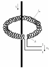
The structure of the proposed lightning flash coun-ter is illustrated in Fig.1. This device is built with the combination of a Rogowski coil, triggering circuit (lightning detection), PIC microcontroller, serial com-munication interface and PC.
The electronic schematic of the whole system is shown in Fig. 2.
The transistor is on when the push button switch is closed and sends a triggering pulse to the monostable multivibrator. After that monostable multivibrator gen-erates an impulse and the PIC detects this impulse. Then three LED will be on and at the same time the PIC sends a signal to the PC through the SCI. A Mobile phone then receives a SMS from the PC.
Fig. 1 Lightning flash counter with SMS data sender.
14
Fig. 2 Electronic schematic of the system.
2.1 Rogowski Coil
A Rogowski coil, named by Walter Rogowski, is an electrical device for measuring alternating current or high-speed current pulses as shown in Fig. 3.
It consists of a helical coil of wire with the lead from one end returning through the center of the coil to the other end, so that both terminals are at the same end of the coil. The inside and outside diameters and height of the Rogowski coil is . The whole assembly is then wrapped around the straight conductor whose current is to be measured. Since the voltage that is induced in the coil is proportional to the rate of change (derivative) of current in the straight conductor, the output of the Rogowski coil is usually connected to an electrical (or electronic) integrator circuit in order to provide an out-put signal that is proportional to the current. In this ap-proach, one integrator block is used after the Rogowski coil. The purpose of placing an integrator with the Rogowski coil is to get its output in terms of induced voltage.
2.2 Lightning Detection Circuit
The basic principle of the lightning detection in this study is that whenever the lightning strikes a structure, the lightning current will be discharged to ground through an existing path (which is mostly a copper down conductor). By encircling the conductor with a Rogowski coil, the voltage will be induced at the output of the Rogowski coil. The induced voltage is then used to trigger the monostable multivibrator for generating a pulse. The monostable multivibrator actually acts as a pulse generator. It is responsive to any induced voltage from the Rogowski coil for generating a pulse with a constant amplitude and pulse width.
2.3 PIC Microcontroller
One of the core components in the electronic light-ning counter circuit is the microcontroller. In this study, the microcontroller that is being used is the microchip microcontroller. As the lightning surge counter needs to be interfaced with a computer, a microcontroller that has in-built serial communication interface is needed. The PIC16F877A has 4 ports with 33 digital I/O pins. It has a wide range of operating voltages that vary from 2.0V to 5.5V.
The microcontroller used in this case is to accom-plish two major tasks. Firstly, it is used to detect the changes at the monostable multivibrator output. Sec-ondly, the microcontroller is used to send signal to the computer through the serial communication interface.
2.4 Serial Communication Interface
The universal synchronous asynchronous receiver transmitter module is one of the two serial I/O modules. USART is also known as a serial communication inter-face. The USART can be configured as a full-duplex asynchronous system that can communicate with pe-ripheral devices such as CRT terminals and personal computers, or it can be configured as a half duplex syn-chronous system that can communicate with peripheral devices such as A/D or D/A integrated circuits, serial EEPROM, etc. In this study, the USART feature is used to transmit a signal to computer. The asynchronous mode is chosen.
III. VISUAL COMPUTER INTERFACE
PROGRAM
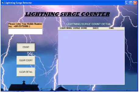
A graphic user interface for this study is created and developed by using Microsoft Visual Basic 6.0. The GUI is an important element here, which is used to record and count each time whenever lightning strikes the particular structure. The graphic user interface is connected to a database which is created using Microsoft Access. The created database consists of two important columns. The first column is used to display how frequent lightning currents discharge through a conductor. The second column is used to record the date and time of each dis-charge.
As the GUI needs to communicate with external hardware, the electronic lightning counter in this study, the band rate and COMPORT for both the GUI and counter need to be matched. This is very important in order to setup a proper connection between the hardware and the software. Fig. 4 shows the graphic user interface for the lightning strike counter system.
3.1 AT Command
AT command is the command that is used to control the GSM modem or mobile phone to perform a task, for example sending a SMS or making a phone call. In this paper, AT command is only used to send out a SMS, and AT command plays an important role as the key ad-vantage is to focus on the auto SMS function.
AT command has been written and tested through the hyper terminal. Before the writing of AT command, the mobile has to be tested in order to determine which type of SMS mode it is supporting. The SMS mode is divided into two types: one is called PDU mode and the other one is called text mode. For PDU mode, the mes-sage content to be sent has to be converted to HEX code before sending is done. For text mode, a SMS can
simp-ly be in the alphabet format that can be written normalsimp-ly. There are also mobile phones that support both types of SMS modes. Therefore, it is easier if mobile phones that support both modes are used.
IV. HARDWARE BUILD
Initially, design works have been completed before the hardware construction. For the construction of the electronic lightning counter, the required components with its specifications are listed in Table 1.
Fig. 4 GUI Interface for lightning counter.
Table 1 Component list.
Components/ Devices Specification
SK40B Starter kit
NPN Transistor BC 546
Push Button 2 / 4 Pins continuity switch
LED 3mm Green, Red
C13 Electrolytic 1.0μF, 50V
C1, C2, C4, C5, C10 Ceramic 0.1μF
C8, C9 Ceramic 27pF
C14 Electrolytic 10μF, 50V
C12 Ceramic 0.01μF
R2 8.2kΩ, ¼ watt
R3 56Ω, ¼ watt
R1 47kΩ, ¼ watt
R5 10kΩ, ¼ watt
R4 100Ω, ¼ watt
R6, R7, R8 220Ω, ¼ watt
D-9 Connector Female
MAX 232 Serial communication
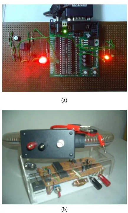
The electronic counter is built on a strip board. The microcontroller used in this study is a four port micro-controller. Additional functions can be added to fully utilize the input/output pins. The SK40B starter kit is bought to be the basic circuit of the counter. The circuit is constructed and soldered on a strip board. Fig. 5 shows the complete prototype of the lightning counter.
V. EXPERIMENTAL RESULTS
Upon the completion of the hardware construction and software development, the lightning surge counter needs to be tested for evaluation on the accuracy and stability of detecting, counting and sending a SMS. A few sets of tests are carried out to test and calibrate the lightning surge counter system. The tests can be divided into two groups: individual tests and overall tests. Under individual tests, every major part of the lightning counter is tested separately while for overall tests, the whole lightning counter system is also tested. The purpose of doing individual tests is to ensure the stability of every single circuit in this study. Besides, it can save time in troubleshooting. Upon the completion of the electronic counter, the electronic counter is put under two individ-ual tests. The first individindivid-ual test is used to test the ac-curacy and stability of the triggering circuit. For the testing, the base of the transistor in the electronic counter circuit that functions as a switch is connected to a 9 VDC battery supply through a push button and a resistor. Once the push button is pressed, the monostable multi-vibrator will generate an impulse waveform at its output, which is connected to the microcontroller. From Fig. 5(a), the functionality of the triggering circuit can be shown through the green LED (LED3).
The second individual test is serial communication interface (SCI) individual test. The functionality of the serial transfer circuit is tested under this test. In order to perform the SCI individual test, Hyper Terminal in a Windows operating system is used. First, the electronic lightning counter is connected to the computer using a serial cable. A few steps need to be followed to set up the Hyper Terminal for the lightning counter. The Hyper Terminal is opened and the setup is completed as shown in Fig. 6. After assigning a name for the connection, a “Connect To” window will pop up, then the user should choose “connect using COM1”. The following steps are filled in every criterion as shown in Figs. 6(a) and (b) respectively:
Once the push button is pressed, the microcontroller will send a signal to the computer through SCI and an letter “A” will appear at the Hyper Terminal. This indi-cates that the SCI can operate as well as expected.
The graphic user interface needs to be tested for its connectivity to the external hardware, which is the light-ning surge counter. The same concept in doing the Hy-per terminal test is applied here. The lightning counter is connected to the computer and the lightning counter graphic user interface is launched. Once the push button
(a)
(b)
Fig. 5 Complete prototype of the lightning counter (a) detec-tion board, (b) Rogowski coil with the detecdetec-tion board unit.
(a) (b)
Fig. 6 Hyper Terminal com port set up.
Fig. 7 Lightning information collected by implemented sys-tem.
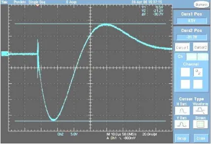
Fig. 8 Rogowski coil voltage invoked by 20 kV surge.
peak respectively. According to the waveform, this voltage consists of the inductive and resistive compo-nents. The inductive component is proportional to the
current derivative, di t( ) dt
and the resistive component
is proportional to the current, ( )i t .
VI. CONCLUSION
In this paper, a low cost lightning counter is de-signed and constructed, which is able to detect and rec-ord the real time of each strike and send a SMS to a user. Experimental results have shown that the designed light-ning surge counter is able to trigger the circuit, able to communicate with a computer and send out a SMS. The proposed lightning surge counter has solved some limi-tations faced by other designs, which are available now-adays. The first key advantage provided by this lightning counter is the ability to send data to a computer and rec-ord the date and time of each strike. As the counter is normally installed on the top of a structure, it is very important to have a good monitoring system towards the counter.
REFERENCES
[1] NGDC-NOAA, “Volcanic Lightning,” National Geophysical Data Center-NOAA, Retrieved Sep-tember 21, 2007.
[2] Munoz, and Rene, “Fact sheet: Lightning.” Univer-sity Corporation for Atmospheric Research, Re-trieved November 7, 2007.
[3] Rakov, and A. Vladimir, “Lightning Makes Glass.” University of Florida, Gainesville. Retrieved No-vember 7, 2007.
[4] E. T. Pierce, “The Influence of Individual Varia-tions in the Field Changes due to Lightning Dis-charges upon the Design and Performance of Lightning Flash Counters,” Arch . Mrt. Geophys. & Bioklim Ser. A , 1956, pp. 76-78.
[5] L. S. Rose, J. A. Stallins and M. L. Bentley, “Con-current Cloud-to-Ground Lightning and Precipita-tion Enhancement in the Atlanta, Georgia Urban Region”, Earth Interactions, Vol. 2, No. 10, 2008, pp.1-30.
[6] R. B. Rodrigues, V. M. F. Mendes and J. P. S. Cat-alao, “Lightning Data Observed with Lightning Location System in Portugal,” IEEE Transactions on Power Delivery, Vol. 25, No. 2, 2010, pp. 870- 875.
[7] R. H. Golde, “Lightning flash counter,” Electrical Research Association of Great Britain Report, July 1957.
[8] B. S. Sonde, “A Transistorized Radiation Field Ac-tuated Lightning Flash Counter,” IEEE Proceedings, Vol. 51, No. 11, Nov. 1963, pp. 1501-1506.
[9] F. de la Rosa and R. Velazquez, “Review of Ground Flash Density Measuring Devices Regard-ing Power System Applications,” IEEE Transac-tions on Power Delivery, Vol. 4, No. 2, April 1989, pp. 921-926.
Hussein Ahmad was born in
and dielectric materials. He is a senior member of the Institute of Electrical and Electronics En-gineers (IEEE), USA.
Md. Abdus Salam (M’97) was
born in Chuadanga, Bangladesh on February 2, 1965. He obtained his B. Sc. in Electrical Engineering from Chittagong University of En-gineering and Technology in 1990, a M. Sc. in Electrical Engineering from Bangladesh University of Engineering and Technology, Dhaka in 1994, and a Ph.D. in high voltage engineering from Universiti Teknologi Malaysia, UTM, Skudai, Jo-hor Darul Takzim, Malaysia in 2000. He worked in the industry from 1990 to 1991. He worked as a Lecturer, was promoted to an Assistant Profes-sor and finally was an Associate ProfesProfes-sor at Chittagong University of Engineering and Tech-nology, in 1994, 1996 and 2001, respectively. He also worked as an Assistant Professor in the De-partment of Electrical and Computer Engineering, College of Engineering, Sultan Qaboos Universi-ty, Muscat, Sultanate of Oman from January 2002 to April 2006. Currently, he has been working as a faculty member in the Department of Electrical and Electronic Engineering, Institute Technology
Brunei, Negara Brunei Darussalam since April 2006. His areas of interest include power system modeling for on line control, insulator pollution studies, grounding systems and hazards of light-ning strikes to overhead transmission lines. He has published 50 papers, where about half of them are in peer reviewed international journals. He is a senior member in the Institute of Electri-cal and Electronics Engineers (IEEE), USA.
Muhammad Abu Bakar Sidik