Baku, Azerbaijan| 177
OPTIMAL CONTROL FOR THREE-PHASE POWER CONVERTERS
SVPWM BASED ON LINEAR QUADRATIC REGULATOR
Hari Sutiksno1, Lie Jasa2, Mochamad Ashari3, Mauridhi Hery Purnomo3
1Sekolah Tinggi Teknik Surabaya (STTS) Surabaya, 2Udayana University Bali, 3Institut Teknologi Sepuluh Nopember (ITS) (INDONESIA)
E-mails: [email protected], [email protected],[email protected], [email protected]
ABSTRACT
A three-phase power converter space vector PWM with current regulation using PI controller typically produces low harmonics distortion and unity power factor with the load change. Nonetheless, its time response of the output voltage is not optimal. This paper proposes an improvement to the conventional three-phase power converter space vector PWM using an optimal control based on the linear quadratic regulator and integral action to improve the output voltage responses. In this paper, the power converter is determined using a linearized state-space model and the parameters of plant model can be found online using the recursive least square algorithm. The feedback and feed forward gains can be obtained based on the linear quadratic regulator to minimize the performance index. In this setting, an integral action is required to eliminate the steady-state error. Using a sinusoidal input, the simulation results demonstrate that, at steady state, the proposed method results in the overshoot of time response of the output voltage of 1.67% with the settling time of 0.05 sec for load changes from full load to half load.
Key words: optimal control, power converter, pulse width modulation, linear quadratic
1. INTRODUCTION
Space vector PWM technique has been used extensively in three phase power converters due to the low harmonic distortion, high efficiency and bidirectional power flow [1-8]. In order for the line current and voltage to be in-phase with certain amplitude, the current regulator must be required. Although the PI controller has typically been used in three-phase power converters, obtaining the optimal time response of the voltage output with respect to the load-change remains challenging due to the fact that the load will likely change the parameters of the plant model. An optimization method has been proposed using the output regulation subspaces and Pulse Width Modulation (PWM) technique taking the advantage of the direct power control strategy [9]. The outcomes show that the overshoot of the dynamics is about 3% and the settling time is about 0.2 sec. The LQR with integral action has also been applied in the design of three-phase three-wire shunt active power filters, giving the overshoot of the output voltage on dynamic load of around 5% with a half cycle settling time [10].Research dealing with constrained optimal control of three-phase Voltage Source Converters (VSC) based on a mathematical model in the synchronous reference frame has also been developed recently [11]. In this instance, the optimal control design to improve the time response of dc voltage on load change based on linear quadratic regulator with integral action is proposed whereby the model of the three phase power converter with current regulator must be linearized. As the parameters of the model vary as the load changes, these parameters must be calculated online by using the recursive least square algorithm. These parameters are used to calculate the performance index. The optimal time response will then be obtained when the performance index reaches the minimum value. Based on the linear quadratic regulator algorithm, both the feedback and feed forward gains can be obtained. The integral action can be added to eliminate the error output voltage. The performance index used in this paper entails the output voltage and input control of the line currents.
2. THREE-PHASE POWER CONVERTER SVPWM WITH CURRENT REGULATOR A. Three-Phase Power Converter
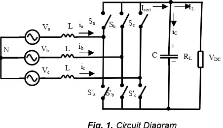
Fig 1 shows the main circuit diagram of the three-phase power converter. The relationship between the currents and the voltages of the ac side can be expressed using the following equations:
dt
d
L
v
ss
v
'
i
(1)
Tc b a
s
v
v
v
v
(2)
Tc b
a
v
v
v
v
'
' ' '(3)
Tc b a
s
i
i
i
178 |
PART A
. NATURAL AND APPLIED SCIENCES
The currents of the dc side can be expressed as
L DC
rect
dt
i
dv
C
i
(5)Meanwhile, the relationship between the voltages and currents of both the dc and ac sides can be obtained respectively using the following equations:
DC
MSv
v
'
(6)
s T
rect
S
i
i
(7) 2 1 1 1 2 1 1 1 2 3 1 M (8)
Tc b
a
S
S
S
S
(9)In equation (9), S indicates the switch position being 1 means ON and 0 means OFF. The space vector PWM technique can then be applied to generate the three phase voltage of the ac side.
Fig. 1.Circuit Diagram B. Current Regulator
In this case, the current regulator in Fig.2 uses an algorithm to produce the reference space vector voltage such that the average line currents over the period Ts for next one period are in phase with the phase voltages of
the power source, with:
)
(
)
(
s s ss
t
T
uv
t
T
i
(10)where u is the input signal. This input value is the ratio of the line currents to the phase voltages of the power source. The voltage reference
v
ref' will be generated as)
(
)
(
)
(
)
2
1
(
)
(
'
I
t
T
L
T
t
I
T
uL
t
v
T
uL
t
v
s s n s n s s nref
(11)Fig. 2. The Plant Diagram Va L
Vb L
Vc L
Sa Sb Sc
S'a S'b S'c
Baku, Azerbaijan| 179
3. OPTIMAL CONTROL BASED ON LINEAR QUADRATIC WITH INTEGRAL ACTION
There are a number of steps required in the design of the optimal control of three phase power converter SVPWM based on linear quadratic regulator with integral action. The first step is to formulate the linearized state space model of the plant whereby the parameters of the plant will be obtained by means of the recursive least square (RLS) algorithm. The second step is to obtain the feedback and feed forward gains using Riccati equation in order to minimize the performance index. The final step is to generate a control signal. Fig.3 shows the block diagram of the proposed system.
Fig. 3.Block Diagram of the proposed system C. Linearized State Space Model
The mathematical model of three-phase power converter SVPWM with current regulation can be derived as follows. The rectified current can be calculated as
)
(
)
(
2
3
)
(
2
)
)
(
(
3
)
(
2
3
)
(
2rec
t
v
v
i
t
v
v
u
t
t
v
v
v
u
t
t
i
DC m DC m m m m DC
(12) L DCL
t
v
R
t
i
(
)
(
)
(13))
(
)
(
)
(
1rec
t
G
v
u
t
t
i
DC
(14)2
3
21
v
mG
(15)where the peak phase voltage
v
m and peak line currenti
m are considered constant along the intervalT
s. The capacitor current can now be derived from the voltage asdt
t
dv
C
t
i
DCC
(
)
(
)
(16))
(
)
(
)
(
t
i
t
i
t
i
rec
C
L (17)From equations (12) to (17), the state equation of the plant can be expressed as
L DC DC DC DC
R
t
v
C
t
v
t
u
C
G
v
u
F
dt
t
dv
1
(
)
)
(
)
(
)
,
(
)
(
1
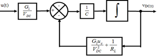
(18)Fig.4 shows the non-linear model of the three-phase power converter with current regulation.
Fig. 4. Non-linear Model of the Three-Phase Power Converter SVPWM with Current Regulator
THREE-PHASE POWER CONVERTER WITH CURRENT REGULATION ESTIMATOR
K v Ku K edt u f DC r ref i
u
refv
DCA,B
u
LINEAR QUADRATURE ALGORITHM
K
fK
r180 |
PART A
. NATURAL AND APPLIED SCIENCES
The linearized model of the state equation (18) can be therefore be formulated as follows
)
)
(
(
)
,
(
)
)
(
(
)
,
(
)
,
(
( , ) (u,V ) DC DCDC DC C V u u DC DC c
DC
v
t
V
v
v
u
F
u
t
u
v
v
u
F
V
u
F
dt
dv
DC c DCc
(19)where DC V u DC
V
C
G
u
v
u
F
DC c1
)
,
(
1 ) , (
(20)C
R
V
u
C
G
v
v
u
F
L DC c V u DC DC DC c1
)
,
(
2 1 ) , (
(21)At steady state, the dc output voltage will move towards a constant value, so the function
F
(
u
c,
V
DC)
must be equal to zero. From equations (19) to (21))
(
)
(
Av
Bu
t
dt
t
dv
DC
DC
(22)where
C
R
V
u
C
G
A
L DC c1
2 1
(23)DC
V
C
G
B
11
(24)Finally, it can be seen from equations (22) and (23), the parameters of power converter model are influenced by the load resistance. The linearized model of the power converter (Fig.5) demonstrates that the parameters of the three-phase power converter model vary with the load changes.
Fig. 5. Linearized Model of the Three-Phase Power Converter SVPWM Recursive Least Square Algorithm
For the simplicity reason, the three-phase power converter SVPWM with current regulator model may be expressed as a linear model. A state space realization of the ARX model is given in discrete equivalent by:
)
(
)
(
)
1
(
k
Av
k
Bu
k
v
DC
DC
(25)The parameters of the plant (A and B) can be estimated by means of the Recursive Least Square (RLS) algorithm, where
v
DC(
k
)
andu
(
k
)
are the regressors.T
B
A
]
[
(26)T
k
u
k
y
k
)
[
(
1
)
(
1
)
]
(
(27)Baku, Azerbaijan| 181
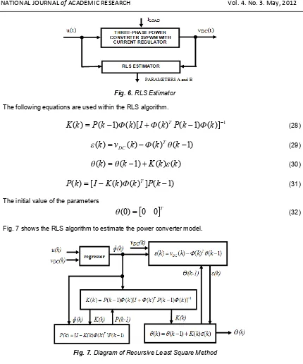
Fig. 6. RLS Estimator The following equations are used within the RLS algorithm.
1
)]
(
)
1
(
)
(
)[
(
)
1
(
)
(
k
P
k
k
I
k
P
k
k
K
T
(28))
1
(
)
(
)
(
)
(
k
v
k
k
Tk
DC
(29))
(
)
(
)
1
(
)
(
k
k
K
k
k
(30))
1
(
]
)
(
)
(
[
)
(
k
I
K
k
k
P
k
P
T (31)The initial value of the parameters
0
0
T)
0
(
(32)Fig. 7 shows the RLS algorithm to estimate the power converter model.
Fig. 7. Diagram of Recursive Least Square Method Linear Quadratic Regulator with integral action
For the system model
v
DC(
k
1
)
Av
DC(
k
)
B
u
(
k
)
, wherev
DC is the output dc voltage andu
is the input signal (control), and the scalar performance index is defined below
0
))
(
)
(
)
)
(
(
)
)
(
((
2
1
k ref
T ref
DC
k
u
y
k
u
u
k
u
k
v
J
Q
R
(33)where J is a scalar performance index Q is a positive semi-definite matrix R is a definite matrix
uref is the command signal (assumed to be constant)
vDC is the output signal
The optimal control sequence that minimizes J is
u
(
k
)
K
fv
DC(
k
)
K
ru
ref (34) The feedback gainK
f in equation (34) is given bySA
B
R
SB
B
K
T T182 |
PART A
. NATURAL AND APPLIED SCIENCES
where S is the solution of the algebraic Riccati equation
Q
A
S
B
R
SB
B
SB
S
A
S
T[
(
T
)
1 T]
(36)and the feed-forward gain
K
r is given byQ
C
BK
A
I
B
R
SB
B
K
T Tf T
T
r
(
)
1[
(
)
]
1 (37)The problem is that equation (34) cannot eliminate the steady state error. A simple way to overcome this is by adding a term proportional to the accumulated error to the controller output. It can be expressed as
)
(
)
(
)
(
k
K
v
k
K
u
K
z
k
u
f DC
r ref
i (38)where
K
i is a constant chosen by the designer and signal z(k) is given by the following recursive formula))
(
(
)
1
(
)
(
k
z
k
u
v
k
z
ref
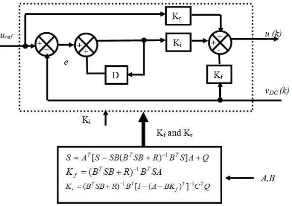
DC (39)Fig.8 shows the optimal algorithm to calculate the feedback and feed-forward gains. In a conventional PI controller, the proportional gain and integral gain will remain constant on the load change and therefore achieving the optimal time response using conventional PI controller is unfeasible.
Fig. 8. Linear Quadrature Algorithm and Control 4. RESULTS AND DISCUSSION
In this simulation experiment, the performance of the optimal control based on linear quadrature with integral action will be compared to that of the PI controller for three-phase power converter SVPWM with current regulation. The parameters of the three-phase power converter SVPWM with current regulation are shown in Table 1. The dynamic performance measures include the time response of the dc voltage generated on load change and the phase difference between the input line current and the phase voltage for both controllers. The load resistance will be varied from the initial load RL=60 Ω to 120 Ω at time 0.5 sec.
Table 1. Parameters of three-phase power converter
Parameter Value
Phase voltage 100 V peak
Frequency 50 Hz
DC bus voltage 300V
Baku, Azerbaijan| 183
Fig. 9 shows the Matlab Simulink block diagram of the power converter using the PI controller. The proportional and the integral gain settings are 0.006 and 0.1 respectively. These gains have been chosen in order to obtain the best time response of the output voltage. Fig.10 shows the simulation results of the time response of the dc voltage on load change using the PI controller, showing the overshoot of approximately 7.5 volt (2.5%) at t=0.5 sec and the settling time of 0.3 sec. In Fig.11, the line current (phase A) is shown between 0.46 sec and 0.56 sec. The peak current changes from 10A to 5A. The wave form of the line current is sinusoidal with 3% total harmonic distortion (THD) and unity power factor.
Fig. 9. Matlab Simulink Diagram of Power Converter with PI Controller
Fig. 10. Time response of output voltage using PI Controller
184 |
PART A
. NATURAL AND APPLIED SCIENCES
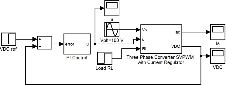
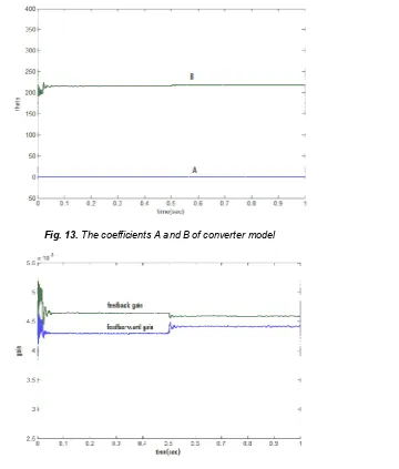
Fig.12 shows the Simulink block diagram of the power converter with optimal control using LQ regulator and integral action. From Fig.13 and Fig.14, it can be seen that the parameters of the power converter model (A and B) and gains (feedback gain Kf and feed forward gain Kr) move towards constant values at less than 0.05 sec at the
initial condition and on load change. This means the time required by the algorithm to estimate the parameters and to obtain the gains is short.
Fig. 12. Matlab Simulink of the Power Converter with Optimal Control using LQ regulator and Integral Action
Fig. 13. The coefficients A and B of converter model
Baku, Azerbaijan| 185
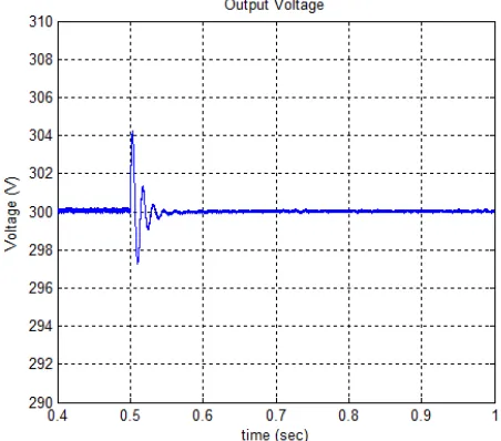
Fig.15 shows the simulation result of the time response of dc voltage on load change using LQR optimal control (Q=1 and R=0.1). The time response of the output voltage oscillates (underdamped) with overshoot of approximately 4 volt (1.33%) and settling time of 0.05 sec. Fig.16 shows the input line current (phase A) changes from 10A peak value to 5A with a sinusoidal waveform with small distortion on steady state. During the transition, however, the waveform of line current is not sinusoidal which occurs in half a cycle.
Fig. 15. Time response of the output voltage on load change with LQR optimal control
Fig. 16. The input line current (phase A) on load change with LQR Optimal Control 5. CONCLUSION
The overshoot of the optimal control of the three-phase power converter SVPWM with current regulation based on linear quadratic with integral action on load change from full load to half load is about 1.33% which is lower than that of the PI controller (2.5%). The settling time of the optimal control is also lower (about 0.05 sec compared to 0.3 sec). Both the input line currents are in phase to the phase voltage (unity power factor) with a relatively low THD of less than 5%. Using the optimal control method, the parameters of the plant model can be obtained online and this allows the controller to be used for various plants. Oscillation occurs at the starting time and every load changes of the optimal control method; however, the interval of the oscillation is less than half a cycle.
REFERENCES
1. Rathnakumar D., Lakshmana Perumal J., Srinivasan T., “A New Software Implementation of Space Vector PWM", SoutheastCon, 2005, Proceeding IEEE, pp.131-136, September 2002.
186 |
PART A
. NATURAL AND APPLIED SCIENCES
3. Iqbal A., Lamine A., Ashra I., Mohibullah, “Matlab/Simulink Model of Space Vector PWM for Three-Phase Voltage Source Inverter ", Universities Power Engineering Conference, 2006. UPEC '06. Proceedings of the 41st International, vol. 3 pp. 1096–1100, 6-8 Sept. 2006.
4. Zheng Zheng; Cong Wang; Haijun Tao, “Research on three-phase PWM rectifier based on predictive control ", ICIT 2008. IEEE International Conference on Industrial Technology pp.1-3, 21-24 April 2008.
5. Saetieo S.; Torrey D.A, “Fuzzy logic control of a space-vector PWM current regulator for three-phase power converters", IEEE Transactions on Power Electronics, vol.13, Issue 3 pp.125-133, May 1998. 6. Min B.-D., Youm J.-H., Kwon B.-H, “SVM-based hysteresis current controller for three-phase PWM
rectifier”, Electric Power Applications, IEE Proceedings, vol 146, Issue 2, pp. 225–230,, March 1999. 7. Sutiksno H; Ashari M.; Mauridhi H.p.; “Neural Predictive Control For A Three-Phase Power Converter
SVPWM With Current Regulator”, Proceedings of the Fourth IASTED International Conference Power and Energy Systems April 2-4, 2008.
8. Sutiksno H; Fadel M; Haroen Y; Ashari M; Mauridhi H.,P; “Load Current Control for Three-Phase Power Converter SVPWM with Current-Regulation”, 14th International Power Electronics and Motion Control Conference, EPE-PEMC 2010
9. Vazquez S.; Leon J.I.; Sanchez J.A.; Galvan E.; Carrasco J.M.; Franquelo L.G.; Dominguez E.; Escobar G. ”Optimized DirectPower Control Strategy using Output Regulation Subspaces and Pulse WidthModulation”, IECON 2006 -32nd Annual Conference on IEEE Industrial Electronics, pp.1896 – 1901, 2006.
10. Bachir Kedjar, Kamal Al-Haddad, ”DSP-Based Implementation of an LQR With Integral Action for a Three-Phase Three-Wire Shunt Active Power Filter”, IEEE Transactions On Industrial Electronics, Vol. 56, No. 8,, pp.2821- 2828 August 2009.