PROPOSAL FOR A NEW LOD AND MULTI-REPRESENTATION CONCEPT FOR
CITYGML
M.-O. Löwner a*, G. Gröger b, J. Benner c, F. Biljecki d, C. Nagel e
a Institute for Geodesy and Photogrammetry, Technische Universität Braunschweig, Germany - [email protected] b CPA Software GmbH, Auf dem Seidenberg 3a, 53721 Siegburg, Germany - [email protected]
c Karlsruhe Institute of Technology, Institute for Applied Computer Science, Germany, [email protected] d 3D Geoinformation, Delft University of Technology, The Netherlands - [email protected] e virtualcitySYSTEMS GmbH, Tauentzienstrasse 7b/c, 10789 Berlin, Germany - [email protected]
KEY WORDS: CityGML, Level of Detail, Multi-representation concept, Application Domain Extension, Profile
ABSTRACT:
The Open Geospatial Consortium (OGC) CityGML standard offers a Level of Detail (LoD) concept that enables the representation of CityGML features from a very detailed to a less detailed description. Due to a rising application variety, the current LoD concept seems to be too inflexible. Here, we present a multi representation concept (MRC) that enables a user-defined definition of LoDs. Because CityGML is an international standard, official profiles of the MRC are proposed. However, encoding of the defined profiles reveals many problems including mapping the conceptual model to the normative encoding, missing technologies and so on. Therefore, we propose to use the MRC as a meta model for the further definition of an LoD concept for CityGML 3.0.
* Corresponding author
1. INTRODUCTION
The Open Geospatial Consortium (OGC) CityGML standard (Gröger et al., 2012; Gröger and Plümer, 2012) is an interoperable data model for the representation of semantically enriched virtual 3D city models. Until now two major releases of the OGC CityGML standard have been published stating from 0.3 in 2006 to the current version 2.0 in 2012 (Löwner et al., 2012). To our knowledge, the OGC CityGML standard is applied in 28 countries for different purposes.
One of the main characteristics of CityGML is the Level of Detail (LoD) concept. Next to the horizontal modularization, the LoD concept offers the possibility to generalize CityGML features from very detailed to a less detailed description. This includes, first, a gradual refinement of the geometrical characteristic, and second, the adjunction of semantic properties. Due to this LoD concept, CityGML is able to represent single buildings, city quarters, whole cities and even regions and, therefore, is suitable for a wide range of different applications. These are e.g. noise propagation simulation and mapping (Czerwinski et al., 2007, Lu et al. in press), fine dust distribution modelling (Ghassoun et al., 2015), urban and telecommunication planning (Köninger and Bartel, 1998, Knapp and Coors, 2008), or real-time simulations for emergency driving training (Randt et al., 2007). CityGML can support even application areas such as emergency management (Zlatanova and Li, 2008) or indoor navigation (Becker et al.,
2009) that require information of the building’s interior on a
city level (rf. Biljecki et al., 2015 for a comprehensive overview of applications). All these models may vary with regard to geometrical and semantical complexity and to the degree of
deviation from the corresponding real world objects. Complexity levels then are the result of specific data acquisition processes or they may be used to assess the suitability of data for specific applications.
The Level of detail (LoD) concept of CityGML is widely accepted by market and by the scientific community (e.g. Boguslawski et al., 2011; Quinn et al., 2009; Iwasczuk and Stilla, 2010; Fan et al., 2009; Götzelmann et al., 2009; Guerke et al., 2009). The term “LoDXmodel” (X {0, 1, 2, 3, 4}) is frequently used to address the complexity of existing city models and their suitability for specific applications. However, mainly due to the emergence of new applications of 3D city models, it has become apparent that the current LoD concept of CityGML is no longer flexible enough. Hence, a number of new approaches entered the discussion. They range from more practice-oriented (Nagel 2014), to very detailed (Benner et al. 2013; Löwner et al., 2013) or even go beyond the context of CityGML (Biljecki et al., 2013; Biljecki et al., 2014; Biljecki et al., 2016a). However, after (rf. Löwner and Gröger, 2016) these proposed concepts vary in richness of aspects, completeness of the concept, completeness of models in a particular LoD, avoidance of inconsistent models, freedom of interpretation, and feasibility and complexity of transformation from CityGML 2.0.
A further feature of CityGML is the Application Domain Extension (ADE) for the extension of the standard. Each ADE is represented by an own XML Schema with a unique namespace. Using an ADE existing CityGML classes may be extended by properties or relations. Further, the user may define even new classes. However, CityGML-ADEs do not contain pure CityGML and, therefore, do not validate against the
CityGML schema but against the specific ADE Schema. This may be a problem for interoperability when different ADEs are in use.
Here we propose a general multi-representation concept (MRC) that is suitable for the representation of first, Levels of Detail in a more flexible way and, second, for the general representation of versions. Thereby it enables new applications that have not been possible by the current concept. That includes for example planning versions of multiple representations in the same LoD. Every feature in CityGML (CityObject) can in principle be represented multiple times by any geometry type: (Multi-)Solid, (Multi-)Surface, (Multi-)Curve, Point, or implicit representation. Profiles can be defined based on the multi-representation concept in order to maintain interoperability of CityGML. Profiles also support backward compatibility with CityGML 2.0. Profiles will be proposed, which define LoD0 to LoD3 in analogy to the current concept, but in a far more flexible way. In particular, LoD4 is replaced by LoD0 – LoD3 for indoor features. New applications of 3D city models such as indoor navigation, facility management or energy applications will be supported. These profiles are optional; users or user groups/communities may define own profiles serving their needs. If the official profiles are referred to in a data set, the corresponding rules have to be met. A proposal for profiles for the building module is presented here. The profiles for the other modules have to be developed accordingly.
In order to be able to automatically validate instance documents with regard to a profile, the MRC is seen as a meta model which can be instantiated by abstract models (UML diagrams) for a specific profile. Hence, validation can be done using standard tools.
In the next section, an overview of the current LoD concept and its deficits is given followed by a review of current suggestions of improvement. Further, we give an overview of multi representational concepts. In Sec. 3 we present our proposal for a general framework for a multi representational concept modelled as an ADE. In Sec. 4 we present profiles of our concept to support interoperability and backward compatibility, to embed CityGML 2.0 data into the multi representational concept and to reduce complexity. Problems of implementation of profiles are discussed in Sec. 5 followed by a conclusion, i.e. the usage of the proposed multi representational concept as a object simultaneously. Scientific approaches focus on the consistency between these representations (Vangenot et al., 2002; Kolbe et al., 2003; Stadler et al., 2007) or the derivation of one representation from another by simplification or generalization methods (see Fan et al., 2009 as one example among many approaches). In our approach, however, we assume that the different representations are given.
The LoD concept typically used in Computer Graphics models and tools is continuous and purely defined with regard to geometrical or graphical aspects, since it targets at efficient visualization (Foley et al., 1995). In contrast, the LoD concept of semantic 3D City Models is defined with regard to both, geometry and semantics, and it is a discrete one.
The LoD concept of CityGML is based on earlier approaches (Köninger and Bartel, 1998; Coors and Flick, 1998). It provides a quality description of a data set and facilitates data integration and interoperability. A particular LoD corresponds to current data capturing methods for 3D city models. Each LoD reflects specific application requirements and, hence, is suitable for a certain class of applications. The same feature can be represented in different LoD, simultaneously. This facilitates analysis and visualization tasks, since tools can dynamically select the most appropriate LoD for a given task. For a detailed description of the current CityGML LoD concept reference is made to (Löwner et al., 2013; Gröger et al., 2012; Gröger and Plümer, 2012). A more general overview of LoD concepts for semantic 3D city models can be found in (Benner et al., 2013). The current LoD concept of CityGML defines five LoD, LoD0 to LoD4. These definitions refer to all thematic features of CityGML, but are here illustrated exemplarily by means of building features. The less detailed level LoD0 defines a 2.5D representation. Buildings are represented by non-vertical polygons, either at roof or at footprint level. In LoD1, volume objects such as buildings are modelled in a generalized way as prismatic block models with vertical walls and horizontal
‘roofs’. In LoD2, the (prototypic) roof shape of buildings is
represented, as well as thematic ground, wall, and roof surfaces along with additional structures such as balconies and dormers. LoD3 is the most detailed level for the outermost shape of objects. For buildings, openings are added as thematic objects. In LoD4, interior structures (rooms, etc.) are added to the most accurate outer representation, which is called LoD4 but almost identically to the LoD3 outer surface.
Several deficiencies of the current LoD concept have been discussed (Benner et al., 2013; Löwner and Gröger 2016; Löwner et al., 2013; Löwner et al., 2015; Biljecki et al., 2013; Biljecki et al., 2014). These are, among others, first, the strict coupling between geometric detail and semantics, second, the preconditions of LoD4 for the interior, and third, only one LoD for interior features.
One of the main characteristics of the CityGML2.0 LOD concept is a strict coupling of semantic and geometric complexity. While, f.i. in LOD0 and LOD1 no further decomposition of a Building or BuildingPart into other feature classes or semantic classification of the geometry is possible, complexity and accuracy of the geometric representation increase for LOD2 to LOD4 together with increased semantic structuring. However, since a specified LOD enforces a certain geometric representation with minimum accuracy, the increase of semantic complexity is only optional.
Openings like windows and doors are restricted to the fine-grained LoD3 and LoD4, which both require a very detailed
geometrical representation of the building’s façade. Openings must not be represented in LoD0 to LoD2. Nevertheless, LoD1 blocks models or LoD2 models with openings are relevant for e.g. energy applications. In order to estimate a building’s energy demand, explicit information on the area covered by windows is essential unlike the façade’s geometry itself (Dalla Costa et al., 2011). Hence, the CityGML 2.0 LoD concept currently hampers such applications. Similarly, BoundarySurfaces are prevented in LoD1, but are relevant for modelling wall properties in energy or other city system analysis applications.
Currently, the building’s interior can only be represented if the exterior shell is represented in LoD4, which implies the highest semantic complexity and geometric detail. This definition hinders applications that require detailed information on the
building’s interior structure without geometrically exact representation of the exterior shell (e.g. firefighting, emergency operations or indoor navigation). Thus, the possibility to
combination of a rough LoD1 or LoD2 model of the exterior shell with a detailed interior model would be beneficial and notably cost-effective. Further, indoor navigation may require the representation of floors, rooms and other interior objects in coarse but not detailed LoD. However, one level (LoD4) is defined for interior features. Especially in the application range of indoor navigation, multiple representations of rooms as well as their movable and non-movable inventory are requested (Domínguez et al., 2011; Becker et al. 2008).
Proposals for improving LoD concepts for semantical 3D building models have been developed that are related to the further development of CityGML (see Löwner and Gröger 2016 for a detailed discussion).
Benner et al. (2013) and Löwner et al. (2013) propose two modifications to enhance the current LoD concept. First, a strict separation between a geometrical and a semantical LoD and, second, the mapping of the current LoD4 to four LoD for the interior. As a result, a building is partitioned into an exterior and an interior, both with one or more explicit LoD of geometrical and semantical aspects.
For geometry, four different representations (LoD0 to LoD3) for all top-level features of the CityGML building model are supported, whether they represent the building’s exterior shell or interior components. (Benner et al., 2013) define four different Semantical Levels (S0 – S3) for the Buildingmodel’s top level features. As for the Geometrical LoD, the Semantical Levels of exterior shell and rooms may be different.
Biljecki et al. (2013) define an LoD as a quality measure with regard to a specific application that could also be used outside CityGML. It is related to a variety of aspects including i.e. richness of feature types, attribute richness, or complexity of geometrical details. They proposed separate hierarchies for geometry and semantics, which have to be defined by the user itself. Further, constraints for each LoD are proposed, which assure the consistency of a certain LoD. An example is a constraint that prevents interior geometries without exterior ones.
Biljecki et al. (2014) later modified this approach with a similar set of aspects. These six aspects are applied to the exterior and the interior of features and span a space of six dimensions, and an LoD is defined as a vector of six values or ranges of values. Only consistentseriesof LoD0, … , LoDn are defined. The main aspects are existence of features, geometrical correspondence between model and reality, and resolution of the appearance. These 10 LoD are roughly a refinement of the LoD0 to LoD4 in CityGML 2.0. The concept is implemented as an Application Domain Extension (ADE) for CityGML. In a subsequent research, Biljecki et al. (2016a) refine the specification into a larger number of LoDs from the geometric point of view to mitigate multiple valid variants of CityGML LoDs (e.g. two geometric instances of LoD2: one with and another one without the roof superstructures modelled). Biljecki et al. (2016b) study the concept of geometric references (multiple variants of the same LoD).
Directly related to CityGML, Nagel (2014) proposed an LoD concept that needs just two definitions (cf. Löwner et al., 2015). First, every city object has a spatial representation in every LoD that refines its spatial representation in higher LoD and, second, there is no restriction on the usage of any feature type in an LoD. Consequently, even feature types that have been
limited to CityGML 2.0 LoD4 now can be used in any lower volumetric features and BoundarySurfaces. An AbstractBuilding, for instance, is then modelled with zero to two instances of a GM_MultiSurface in LoD0, representing the footprint or the edges of a roof. For the representation in LoD1-LoD3 it is modelled as a GM_MultiSurface or as a GM_Solid, respectively. An AbstractBoundarySurface, which might be possible in all four LoD is represented by a GM_MultiCurve in LoD0 and zero to one GM_MultiSurfaces in LoD1-LoD3. Here, the curve representation stands for the footprint as a spatial abstraction of that wall surface.
3. GENERAL FRAMEWORK FOR A MULTI REPRESENATIONAL CONCEPT
We propose a geometrical representation concept that allows any geometric representation for any CityGML object multiple times. This covers the representations already supported by CityGML 2.0, e.g. a MultiSurface representation of an outer wall surface. Further, it allows to additionally define new representations (e.g. representing a wall as a line in a floorplan). Hence, the proposed framework defines a multi-representation concept, in which the LoD is only one aspect among others. The proposed concept adapts ideas of the Industry Foundation Classes (IFC) standard (Liebig, 2007) and is based on previous work of the authors (Biljecki et al., 2013; Biljecki et al., 2014; Biljecki et al., 2016a; Benner et al., 2013; Nagel, 2014; Löwner et al. 2013; Löwner et al, 2015; Löwner and Gröger, 2016).
In the CityGML 2.0 conceptual data model, every feature type is geometrically represented by specific properties. For example, the class _AbstractBuilding has 13 geometry properties to represent the exterior shell of a building in five different LoD. We propose to replace the specific geometry properties of selected features by one geometry property of the base class _CityObject. This property, which is inherited by all CityGML feature types, covers all geometry types (0, 1, 2 and 3-dimensional) actually used in any CityGML 2.0 module. The proposed geometrical representation can be instantiated multiple times. Hence, every CityGML feature type can be represented multiple times with arbitrary geometrical representation.
In the following, we discuss the UML model of this multi-representation property. For testing and demonstration purposes, it is actually implemented as Application Domain Extension (ADE) of CityGML 2.0.
The UML class diagram extending _CityObject by arbitrary geometrical representation is depicted in Figure 1. By using the ADE mechanism, the base class CityObject is extended by a relation representation, pointing to a new data type AbstractRepresentation. This is the base class for all representations of CityGML features. Actually, only geometry-based representations (class ShapeRepresentation) are supported, but in future extensions, other types of feature representation (e.g. topological representation) might be regarded. The cardinality of the representation property is 0..*, which means that features without geometrical representation as
well as multiple geometrical representations of the same feature are possible
For differentiating and semantically classifying different representations, the type RepresentationContext is introduced. Every representation must be related with exactly one RepresentationContext object, which is uniquely identified by a contextIdentifier of type URI. For a more detailed representation model, additional optional properties (contextName and precision) are provided.
The RepresentationContext can be regarded as generalization of the existing LoD concept. It is assumed that (geometrical) representations of different features belonging to the same context are consistent with respect to generation method and geometrical accuracy. In consequence, visualization and processing applications in general can only integrate features belonging to the same representation context.
In the most general case, a ShapeRepresentation object can be composed of one or more geometrical representations, which are all derived from the abstract data type AbstractShapeRepresentation. The geometry types depicted in Figure 1 comprising all types used in CityGML 2.0. This ensures the transfer of every geometrical representation of a CityGML 2.0 feature into the new concept.
In some cases, a feature is represented by multiple geometry objects of the same type. One example is the BreaklineRelief in the module Digital Terrain Model, which is modelled by two line sets representing break lines and ridges or valley lines. For reconstructing the terrain structure from these data, it is essential to know which of the MultiCurves represent which line set. In order to express this semantical information in the new representation model, the super class AbstractShapeRepresentation has on optional property representationIdentifier.
«featureType»
CityGML_Core::_CityObject
«ADEElement»
_CityObj ect
+ guid :CharacterString [0..1]
«dataType»
ShapeRepresentation
«dataType»
AbstractShapeRepresentationItem
+ representationIdentifier :CharacterString [0..1]
«type»
RepresentationContext
+ contextIdentifier :URI
+ contextName :CharacterString [0..1] + precision :Decimal [0..1]
«dataType»
GeometryRepresentation
+ geometryProperty :GM_Object
«dataType»
AbstractRepresentation
«dataType»
PointRepresentation
+ geometryProperty :GM_Point
«dataType»
MultiPointRepresentation
+ geometryProperty :GM_MultiPoint
«dataType»
Curv eRepresentation
+ geometryProperty :GM_Curve
«dataType»
SurfaceRepresentation
+ geometryProperty :GM_Surface
«dataType»
SolidRepresentation
+ geometryProperty :GM_Solid
«dataType»
MultiCurv eRepresentation
+ geometryProperty :GM_MultiCurve
«dataType»
MultiSurfaceRepresentation
+ geometryProperty :GM_MultiSurface
«dataType»
MultiSolidRepresentation
+ geometryProperty :GM_MultiSolid
«dataType»
ImplicitRepresentation
«type»
CityGML_Core::ImplicitGeometry
«dataType»
TriangulatedSurfaceRepresentation
+ geometryProperty :GM_T riangulatedSurface
«dataType»
Cov erageRepresentation
+ geometryProperty :GM_RectifiedGridCoverage
+representationItem 1..*
+geometryProperty 1 *
+context
1 +representation 0..*
Figure 1. UML class diagram of the proposed multi representation concept as a CityGML 2.0 ADE.
4. PROFILES SUPPORTING BACKWARD
COMPATIBILITY AND INTEROPERABILITY
The proposed multi representation concept is very flexible and generic. Each feature type can be represented multiple times by arbitrary geometry types with no standardized names of the representations represented by contextIdentifiers. For exchanging 3D city model data or for the specification of requirements for data sets, for example in calls for tender, such a concept has to be extended by more specific and precise definitions of the particular levels A first step is to define Profiles for this task. Profiles restrict the variability of geometric representations and support generation and interpretation of CityGML. Furthermore, they support embedding of the current CityGML LoD concept. The profiles defined in this paper are a special case of the more general ISO TC 211 profiles used to extend as well as to restrict schemas (ISO 19106:2004).
The structure of a profile is simple: a profile assigns a geometry type (point, surface, solid, etc.) and a geometric definition to each feature type. A profile is uniquely identified by an URI called contextIdentifier (c.f. the UML diagram in Sec. 3). It consists of the level (in a specific namespace) together with the module name and the feature type name.
There are several options how profiles can be used. Every organization, user community or user may define customized
profiles based on the multi representation concept. We propose two standardized sets of profiles, which could be defined in the specification document of further versions of CityGML. The first set ensures backward compatibility for dealing with current CityGML data. The names of the profiles correspond to the current LoD names. The second set of profiles ensures interoperability when 3D City Models are exchanged. These profiles will play the same role as the current concept, but are more flexible and cover more relevant applications.
In the following subsections, we present the two sets of profiles, specifically for the building module. The profiles for the tunnel and bridge modules (which both have a structure similar to the building module) can be derived from these in a straightforward way. The profiles for the other modules of CityGML can be derived analogously.
4.1 PROFILES FOR EMBEDDED CITYGML 2.0 DATA SETS IN THE MULTI REPRESENTATION CONCEPT
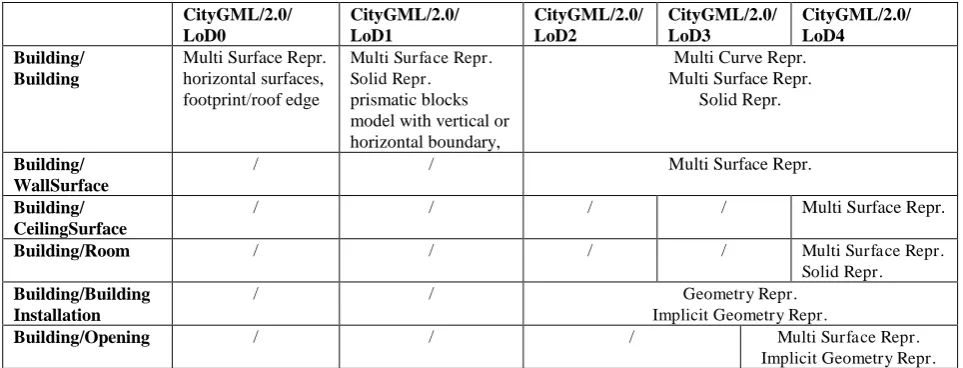
The set of profiles which assure backward compatibility for current CityGML datasets are given in Table 1 for the building module as an example. The geometry types as well as the definitions of geometry correspond to the types defined in the current UML diagrams of CityGML.
The contextIdentifiers are derived from the current LoD names (in namespace CityGML/2.0) combined with the names of modules and feature types. The profile for buildings in module building in LoD2, for example, has the contextIdentifier CityGML2.0/LoD2/Building/Building.
CityGML/2.0/ LoD0
CityGML/2.0/ LoD1
CityGML/2.0/ LoD2
CityGML/2.0/ LoD3
CityGML/2.0/ LoD4 Building/
Building
Multi Surface Repr. horizontal surfaces, footprint/roof edge
Multi Surface Repr. Solid Repr. prismatic blocks model with vertical or horizontal boundary,
Multi Curve Repr. Multi Surface Repr.
Solid Repr.
Building/ WallSurface
/ / Multi Surface Repr.
Building/ CeilingSurface
/ / / / Multi Surface Repr.
Building/Room / / / / Multi Surface Repr.
Solid Repr. Building/Building
Installation
/ / Geometry Repr.
Implicit Geometry Repr.
Building/Opening / / / Multi Surface Repr.
Implicit Geometry Repr.
Table 1. Profiles for backward compatibility (for abbreviations and explanations see the remarks for Table 2 ). Geometry types in italics are used mutually exclusively in one profile. For each feature type of the building module, several profiles are defined. The
table defines in total 28 profiles, the contextIdentifiers of which are a combination of a level name in the first row and a module/feature type name in the first column.
4.2 PROPOSAL FOR PROFILES FOR ENABLING INTEROPERABILITY
The main requirement for the set of future interoperability profiles is that the new applications mentioned in the motivation
are covered. Therefore, LoD4 has been replaced by LoD0 to LoD3 for exterior and indoor objects and all feature types can be represented in each LoD. The definitions for LoD0 to LoD3 are in principle identical to the current definitions, but have been extended to all feature types.
In particular, an LoD0 representation is provided for all feature types. LoD0 is defined as the projection of the corresponding LoD1 geometry onto a non-vertical surface. Hence, the dimension of an LoD0 geometry is always one lesser than the dimension of the corresponding LoD1 geometry.
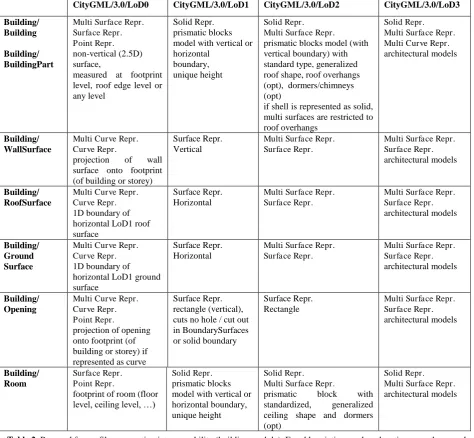
The set of future interoperability profiles for the building module are given in Table 2. For the description of the particular geometries, two definitions are used: a geometry is horizontal, if all points have the same z-coordinate. A surface is vertical, if the normal of the surface is horizontal. The abbreviation opt means that a property is optional. If the geometry types are denoted in italics, there is an exclusive-or relation between these geometries: exactly one of the
representations is used for the geometrical representation of a feature.
The geometry representations have been borrowed from the current CityGML version. In particular, Geometry Representation is the most general geometry representation and Implicit Geometry Representation has been defined in CityGML as prototypic geometry which can be parametrized.
The potential of the new concept is illustrated by the examples in Figure 2 to Figure 4, which are outside the scope of the current concept and which are relevant for the applications mentioned in the introduction. Figure 2 shows a building where the exterior shell as well as rooms are represented in LoD0. Both feature types are represented in LoD2 in Figure 3. A LoD2 building with LoD1 Openings is depicted in Figure 4.
Table 2. Proposal for profiles supporting interoperability (building module). For abbreviations and explanations, see the remarks in the text. Geometry types in italics are used mutually exclusively in one profile. The contextIdentifiers of the profiles are a
combination of a level name in the first row and a module/feature type name in the first column.
CityGML/3.0/LoD0 CityGML/3.0/LoD1 CityGML/3.0/LoD2 CityGML/3.0/LoD3 Building/
if shell is represented as solid, multi surfaces are restricted to
Figure 2. LoD0 representation of the exterior and the interior (rooms) of buildings.
Figure 3.. LoD2 representation of a building (exterior) and of rooms.
Figure 4. A coarse representation of the exterior of a building with openings.
5. WAYS OF PROFILE IMPLEMENTATION AND THEIR RESTRICTIONS
The proposed multi representation concept has been defined on a conceptual level using the Unified Modelling Language (UML) and could therefore be easily be transferred to an XML encoding, which could define the normative part of CityGML. Since the profiles for the definition of Levels of Detail are defined in natural language, they have to be transferred to the XML based encoding standard, also. However, encoding must be verifiable against the conceptual model. Therefore, a mapping of UML to XML and vice versa has to be ensured. For the definition of the aforementioned profiles, three options are given, the Object Constrained Language (OCL), XML Schematron, and predefined geometry attributes.
The Object Constrained Language (OCL) is a declarative Language and part of the Unified Modeling Language Standard (OMG, 2014). It enables the formulation of rules for UML classes that control validity of their instances.
Main drawback of utilizing OCL for the definition of profiles restricting the flexibility of the multi representation concept are confusing UML diagrams containing very long OCL statements. The lack of software tools supporting the definition of valid OCL expressions worsens the situation.
Loss of OCL constraints when mapping UML to GML is another major problem since further development of existing tools like e.g. ShapeChange seems to be quite costly. However, automatic mapping of the conceptual UML to the normative implementation of GML is one major task of the new release of CityGML 3.0. Finally, the question raises, how the LoD profiles of the MRC can be evaluated automatically. Implementation of validation mechanisms along with every single CityGML reading tool in our opinion risks interoperability of exchanged instance documents.
Hence, OCL, theoretically, would enable the forma definition of the proposed profiles, but practical implementation is far away from being better than unformal definition tables in sec. 4.1 and 4.2.
Schematron could be used as an alternative to OCL helping in implementing the LoD profiles. Schematron is a formal language for the validation of content and structure of XML documents and structure. It is part of the ISO ISO/IEC 19757 (ISO/IEC 19757-3,2006) and can directly be applied to GML files. The CityGML 2.0 encoding standard already makes use of Schematron 1.5 (Jelliffe, 2002) to describe referential integrity constraints on CityGML property elements denoting the relation between CityGML objects.
The advantages of this approach would be that rules defined in Schematron could be validated automatically having sufficient tools at hand. Further, Schematron could be delivered included in the CityGML XML Schema and, it could also be applied to let user put constraints on their own context when extending the MRC. However, the latter would call for rules to define and publish Schematron based constraints, f.i. an additional URI containing set of constraints for each ShapeRepresentation. However, again disadvantages of this approach outweigh its advantages. First, Schematron rules are defined in the CityGML implementation standard and not at the level of the conceptual UML model. Deriving Schematron rules from one and the other level would again incorporate a lot of OCL with all its aforementioned disadvantages. The only conceivable solution would be the publication of rules in CityGML specification. Since this seems not to be in sight only manual mapping from linguistic descriptions, e.g. the content of Table 1 and Table 2 to Schematron could be performed. That would result in a huge
amount of work, especially for the definition of rules to define and publish Schematron constraints in a CityGML context. Hence, Schematron could be applied to formalize profiles but this would cause considerable work and would leave the user in uncertainty concerning the definition of own Schematron rules. Further, derivation of UML and XML is hindered.
Predefined geometry attributes for each feature type on the conceptual level is the last of our proposals to introduce MRC to CityGML 3.0. This would result in two UML models, the MRC and the model for each feature types and, therefore, an inadmissible duplicated structure of UML models. To solve this, one could propose to model geometry attributes only for the encoding standard. Again, this solution would lead to unsolvable problems when mapping the conceptual UML to the normative encoding XML and to any other encodings that might be desirable for the user.
To sum up, we see no direct way to introduce the MRC with its outstanding advantages, which neither results in a huge amount of work, a confusing standard. All the three discussed solutions would endanger the acceptance of the standard and interoperability. Therefore, we prefer a fourth way to keep the ideas of the MRC and to ensure consistent models on the conceptual as well as on the encoding level.
Here, we propose to keep the multi-representation model as a
guiding principle when defining CityGML’s 3.0 LoDs. Due to
the reasons discussed above it should not be modelled as UML model for the further usage in profiles. We argue that the following two paths should be forged to keep the idea of the MRC without the need of inapplicable profiles:
First, LoD specific geometry representations will be modelled as geometry attributes for each feature type. Modelling results would represent the implementation of the MRC profiles discussed in Sec. 4 without the need of defining the profiles. The advantage would be the possibility of directly mapping UML to GML and an easy validation of CityGML instance models. The result would be quite similar to the CityGML 2.0 LoD definition, albeit with different content.
Second, any desired user specific geometry representations for feature types should be allowed using the ADE mechanism. Remember, rules for the application of ADEs are already defined and tools support the mapping of UML to GML. The possibility to develop own ADEs on the basis of the MRC let the user still benefit from its flexibility.
However, a still unsolved question is the assignment of the user defined LoDs to the ones already defined in the standard. A possible solution is the usage of the ContextIdentifyer (r.f Sec. 3) as an attribute name, f.i. ade:lod2EnergeticHull.This would call for customized tool in the CityGML toolchain.
Using the MRC as a meta model for the further development of CityGML would reveal the following advantages:
First, content of the profiles discussed in Sec. 4 remains with their advantages concerning new applications and clear definition of LoDs. User defined LoD ADEs are, of course, still possible. Second, no profiles are needed in the standard and, therefore, new rules or tools are unnecessary. Third, the envisaged result has the look and feel of CityGML 2.0 facilitating the implementation and supports user acceptance. Last, no contradiction between the ADE mechanism and the general MRC will be installed. Since ADEs are already supported by some tools, it will be the only official way to extend the CityGML schema.
6. CONCLUSION
In this paper, we presented a multi-representational concept as a proposal for the further development of the Level of Detail concept of CityGML, the international OGC standard for semantical 3D city models. Problems of the current concept related proposals for improvements are discussed, all having their strong and weak points but widening the scope of CityGML.
We present a concept that allows multiple geometric representations for any CityGML object. Thus, the proposed concept defines a multi-representation concept, in which the LoD is only one aspect among others, e.g. versions. The RepresentationContext was regarded as a generalization of the existing level names of the LoD concept assuming that representations of different features belonging to the same context are consistent with respect to generation method and accuracy. Hence, only features of the same RepresentatioContext can be processed at a time.
For the specification and exchange of 3D city model data we propose profiles to restrict the variability of the very flexible and generic MRC in a descriptive way. We propose two standardized sets of profiles, first, to ensure backward compatibility for dealing with current CityGML data, and second, to ensure interoperability. These profiles restrict the MRC to a certain extent but let the user still cover more relevant applications.
However, all proposed approaches to formally define the discussed profiles and to validate instance documents fail in terms of missing tools or complexity. OCL suffers from missing tools, very long statements and the inability to be transferred from UML to XML, automatically. Schematron is weak and would call for very complex rules for the definition of user specific rules applying the MRC. Restricting the MRC by profiles defining predefined geometry attributes would again call for a mechanism to formulize these profiles. Direct modelling of feature types with LoD geometry attributes would conflict with the MRC.
As a conclusion, we propose to keep the multi-representation model as a meta model and to model LoD specific geometry representations to represent the profiles discussed in Sec. 4. In addition, any specific geometry representation for feature types should be possible using the ADE mechanism.
Advantages would be to keep the idea of a MRC for flexibility reasons, provide a consistent model in both, the conceptual and encoding level and to prevent conflicts of a MRC meta model with the ADE mechanism. Next to this, the CityGML 3.0 LoD concept will allow for more applications and will be modelled in a familiar way to enhance the user’s acceptance.
ACKNOWLEDGEMENTS
We acknowledge the members of the Modelling Working Group of the Special Interest Group 3D of GDI-DE and the members of the Open Geospatial Consortium CityGML-3.0 Work Package 3 for their contributions and vivid discussions.
REFERENCES
Becker, T., Nagel, C., Kolbe, T. H., 2009. A Multilayered Space-Event Model for Navigation in Indoor Spaces. In: Lecture Notes in Geoinformation and Cartography: 3D Geo-Information Sciences: 61-77.
Benner, J., 2013. Revision of the CityGML LoD concept, Change Request No. 13-089, Open Geospatial Consortium, URL: https://portal.opengeospatial.org/files/?artifact_id=55980
Benner, J., Geiger, A., Gröger, G., Häfele, K.H., Löwner, M.O., 2013. Enhanced LoD Concepts for Virtual 3D City Models – ISPRS Annals of the Photogrammetry, Remote Sensing and Spatial Information Sciences II-2/W1: 51–61.
Biljecki, F., Ledoux, H., Stoter, J., Zhao, J., 2014. Formalisation of the level of detail in 3D city modelling – Computers, Environment and Urban Systems 48: 1–15.
Biljecki, F., Ledoux, H., Stoter, J., 2016a. An improved LOD specification for 3D building models – Computers, Environment and Urban Systems 59: 25–37.
Biljecki, F., Ledoux, H., Stoter, J., Vosselman, G., 2016b. The variants of an LOD of a 3D building model and their influence on spatial analyses – ISPRS Journal of Photogrammetry and Remote Sensing 116: 42–54.
Biljecki, F., Stoter, J., Ledoux, H., Zlatanova, S., Çöltekin, A., 2015. Applications of 3D City Models: State of the Art Review
– ISPRS International Journal of Geo-Information 4(4): 2842-2889.
Biljecki, F., Zhao, J., Stoter, J., Ledoux, H., 2013. Revisiting the concept of level of detail in 3D City Modelling – ISPRS Annals of the Photogrammetry, Remote Sensing and Spatial Information Sciences II-2/W1: 63-74.
Boguslawski, P., Gold, C. & Ledoux, H., 2011: Modelling and analysing 3D buildings with a primal/dual data structure – ISPRS Journal of Photogrammetry and Remote Sensing 66(2): 188–197.
Coors, V., Flick, S., 1998. Integrating Levels of Detail in a Web-based 3D-GIS. In: Laurini, R., Makki, K., Pissinou, N. (Eds.), ACM-GIS '98, Proceedings of the 6th international symposium on Advances in Geographic Information Systems, November 6-7, 1998, Washington, DC, USA. ACM Press.
Czerwinski, A., Sandmann, S., Stöcker-Meier, E. and Plümer, L., 2007. Sustainable SDI for EU noise mapping in NRW – best practice for INSPIRE – International Journal for Spatial Data Infrastructure Research 2(1): 90–111.
Dalla Costa, S., Roccatello, E., Rumor, M., 2011. A CityGML 3D Geodatabase for Buildings Energy Efficiency – International Archives of the Photogrammetry, Remote Sensing and Spatial Information Sciences XXXVIII-4/C21: 19–24.
Domínguez, B., García, Á., Feito, F.R., 2011. Semantic and topological representation of building indoors: an overview – The Joint ISPRS Workshop on 3D City Modelling & Applications and the 6th 3D GeoInfo Conference, Wuhan, China.
Fan, H., Meng, L., Jahnke, M., 2009. Generalization of 3D Buildings Modelled by CityGML – SESTER, M. et al. (eds.): Advances in GIScience. – 12th AGILE Conference, Lecture Notes in Geoinformation and Cartography: 387–405, Springer, Berlin Heidelberg.
Foley, J., van Dam, A., Feiner, S., Hughes, J., 2002. Computer Graphics: Principles and Practice. Addison Wesley, 2nd Ed.
Ghassoun, Y., Löwner, M.O. & Weber, S., 2015. Exploring the Benefits of 3D city Models in the Field of Urban Particles Distribution Modelling – a Comparison of Model Results. – Breunig, M. et al. (eds.): 3D Geoinformation Science, the Selected Papers of the 3D GeoInfo 2014 – Lecture Notes in Geoinformation and Cartography: 193–205, Springer.
Götzelmann, T., Guerke, R., Brenner, C., Sester, M., 2009. Terrain-Dependent Aggregation of 3D City Models – ISPRS-Workshop on quality, scale and analysis aspects of city models.
– International Archives of the Photogrammetry, Remote Sensing and Spatial Information Sciences XXXVIII-2/W11, Lund, Sweden.
Gröger, G., Kolbe, T. H., Nagel, C., Häfele, K.H., 2012. OpenGIS® City Geography Markup Language (CityGML) Encoding Standard, Version 2.0.0, OGC 08-007r2.
Gröger, G. and Plümer, L., 2012. CityGML – Interoperable semantic 3D City Models. – ISPRS Journal of Photogrammetry and Remote Sensing 71: 12–33.
Guerke, R., Brenner, C., Sester, M., 2009. Generalization of 3D City Models as a Service. – ISPRS-Workshop on quality, scale and analysis aspects of city models, International Archives of the Photogrammetry, Remote Sensing and Spatial In-formation Sciences, XXXVIII-2/W11, Lund, Sweden.
Iwaszczuk, D., Stilla, U., 2010: A Concept for the Assignment of Textures to Partially occluded Faces of 3D City Models stored in CityGML – KOLBE, T.H. et al. (eds.): 5th ISPRS International 3D GeoInfo Conference, Germany. – International Archives of the Photogrammetry, Remote Sensing and Spatial Information Sciences XXXVIII-4/W15: 57–62, Berlin.
ISO/IEC 19757-3 (2006): Information technology - Document Schema Definition Languages (DSDL) - Part 3: Rule-based validation - Schematron. 30 pp.
Jelliffe, R. (ed.) The Schematron Assertion Language 1.5.
2002-10-01. URL:
http://xml.ascc.net/resource/schematron/Schematron2000.html (last visited 30/05/2016)
Knapp, S. & Coors, V., 2008: The use of eParticipation in public participation: The VEPs example. – Coors, V. et al. (eds.): Urban and regional data management. – Urban Data Management Society Symposium 2007 (UDMS Annual 2007), BALKEMA-proceedings and monographs in engineering, water and earth sciences: 93–104, Taylor & Francis, London, UK.
Köninger, A., Bartel, S., 1998. 3D-GIS for Urban Purposes – Geoinformatica 2 (2): 79–103.
Liebich, T. 2007: INDUSTRY FOUNDATION CLASSES - IFC2x3 Documentation, 2007.rmation Sciences XXXVIII-4/W15: 57–62, Berlin.
Löwner, M.O., Benner, J., Gröger, G., 2015: Aktuelle Trends in der Entwicklung von CityGML3.0. – Seyfert, E. et al. (eds.): Geoinformationen öffnen das Tor zur Welt, 34. Wissenschaftlich-Technische Jahrestagung der DGPF, Tagungsband 23, Hamburg.
Löwner, M.-O., Benner, J., Gröger, G., Gruber, U., Häfele, K.-H. & Schlüter, S. (2012): CityGML 2.0 - ein internationaler Standard für 3D-Stadtmodelle, Teil 1: Datenmodell. Zeitschrift
für Geodäsie, Geoinformation und Landmanagement, 6/2012, 340 - 349.
Löwner, M.O., Benner, J., Gröger, G. & Häfele, K.H., 2013: New Concepts for Structuring 3D City models – an extended Level of Detail concept for CityGML Buildings. – Murgante, B. et al. (eds.): 13th International Conference on Computational Science and its Applications, Part III, LNCS 7973: 466–480, Springer, Berlin.
Löwner, M.O., Gröger, G., 2016: New Criteria for the Evaluation of Recent LoD Proposals for Buildings in CityGML
– Photogrammetrie, Fernerkundung, Geoinformation 1/2016: 31-43.
Lu L., Becker, T. & Löwner, M.-O. (in press): 3D Complete Traffic Noise Analysis Based on CityGML. Abdul-Rahman, a (ed.): Advances in 3D Geoinformation. Lecture Notes in Geoinformation and Cartography.
Nagel, C., 2014: Proposal for a revision of the CityGML LOD concept. – Presentation at the 5th Meeting of OGC Working Package 3 for the revision of the LoD concept for CityGML 3.0, 20.10.2014, https://github.com/opengeospatial/CityGML-3.0/blob/master/WP%2003%20Resources/Meetings/1st/WP03_ 2014_07_09_Nagel_Proposal_for_a_Revision-of-the-LOD-Concept.pdf (1.11.2015).
Object Modelling Group (OMG), 2014. Object Constraint Language, Version 2.4. OMG Document Number:
formal/2014-02-03, Standard document URL:
http://www.omg.org/spec/OCL/2.4
Quinn, J.A., Smart, P.D., Jones, C.B., 2009: 3D city registration and enrichment. – ISPRS-Workshop on quality, scale and analysis aspects of city models, International Archives of the Photogrammetry, Remote Sensing and Spatial Information Sciences XXXVIII-2/W11, Lund, Sweden.
Randt, B., Bildstein, F. & Kolbe, T.H., 2007: Use of Virtual 3D Landscapes for Emergency Driver Training – 2007 IMAGE Conference, Scottsdale, AZ, USA.
Stadler, A., Kolbe, T.H., 2007. Spatio-semantic coherence in the integration of 3d city models. In: 5th Int. ISPRS Symp. on Spatial Data Quality. 13-15 June 2007, ITC, Enschede.
Vangenot, C., Parent, C., Spaccapietra, S., 2002. Modelling and manipulating multiple representations of spatial data – Proceedings of the 10th International Symposium on Spatial Data Handling, pp. 81-93.
Zlatanova, S., Li, J.. 2008. Geospatial Information Technology for Emergency Response, Taylor and Francis, Leiden, NL, 2008.