I
NTRODUCTION OF A PHOTOGRAMMETRIC CAMERA SYSTEM FOR RPAS WITH
HIGHLY ACCURATE GNSS
/
IMU INFORMATION FOR STANDARDIZED WORKFLOWS
T. Kraft a, M. Geßner a, H. Meißner a, H. J. Przybilla b, M. Gerke c
a
Institute of Optical Sensor Systems, German Aerospace Center (DLR), Berlin, Germany - (Thomas.Kraft, Matthias.Gessner, Henry.Meissner)@dlr.de
b
Department of Geodesy, University of Applied Sciences, Bochum, Germany - [email protected]
c
ITC, University of Twente, 7500 AE Enschede, Netherlands - [email protected]
ICWG III/I
KEY WORDS: UAV, RPAS, Modular Airborne Camera System, MACS, Metric Camera, Direct Georeference, RTK-GNSS
ABSTRACT:
In this paper we present the evaluation of DLR’s modular airborne camera system MACS-Micro for remotely piloted aircraft system (RPAS) with a maximum takeoff weight (MTOW) less than 5kg. The main focus is on standardized calibration and test procedures as well as on standardized photogrammetric workflows as a proof of feasibility for this aerial camera concept. The prototype consists of an industrial grade frame imaging camera and a compact GNSS/IMU solution which are operated by an embedded PC. The camera has been calibrated pre- and post- flight using a three dimensional test field. The validation of the latest prototype is done by a traditional photogrammetric evaluation of an aerial survey using 39 ground control points. The results, concerning geometric and radiometric features of the present system concept as well as the quality of the aero triangulation, fulfill many of the aimed key-specifications.
1. INTRODUTCION
The increasing number of RPAS for aerial mapping purposes (e.g. agriculture, mining, archaeology, object- and building inspection) led to a demand for appropriate photogrammetric mapping solutions. Within the German Society of Photogrammetry, Remote Sensing and Geoinformation (DGPF) there was and still is an active debate about RPAS based photogrammetric mapping. The debate is focused on how such an aerial camera system has to be designed and what key-specifications have to be met.
The use of consumer cameras (e.g. Sony NEX 5R, Sony Alpha 7R, Fuji X-M1, Panasonic Lumix DMC-TZ71) in combination with computer vision based software solutions (e.g. Pix4D, Agisoft Photoscan) has been proven by several working groups and shows impressive results for mapping and object reconstruction purposes (CRAMER ET AL.,2013; PRZYBILLA ET AL.,2015;NEX ET AL.,2015;HARWIN AND LUCIEER,2012). Only a few dedicated aerial camera systems for RPAS have been presented (MARTIN ET AL., 2014; BRAUCHLE ET AL., 2014; STEBNER AND WIEDEN,2014) which will meet the main criteria of conventional aerial mapping cameras. This implies the utilization of radiometric and geometric calibrated imaging sensors to enable reliable interior orientation parameters. To determine reliable exterior orientation parameters an appropriate GNSS and IMU solution is mandatory. To gain highest accuracies a post-processing of the trajectory is recommended in combination with a deterministic concept of geo-referencing each image. If these criteria are satisfied a photogrammetric image processing is achievable like it is common for conventional aerial mapping cameras.
Due to national law restrictions (GERMAN FEDERAL MINISTRY OF
TRANSPORT AND DIGITAL INFRASTRUCTURE, 2014) the use of RPAS less 5kg MTOW is quite popular and this was the intention to develop a lightweight aerial camera system using industrial grade components based on DLR’s modular airborne camera system (LEHMANN ET AL.,2011). A first prototype of MACS-Micro has been developed and verified by a traditional photogrammetric evaluation.
2. CONCEPT OF MACS-MICRO
The frame imaging part (Fig. 1) consists of an industrial grade camera module with a 12 Megapixel CMOS chip (4.7µm pixel pitch, Bayer pattern, global shutter mode) and an industrial C-Mount lens (APO Xenoplan f2.0 24mm).
Figure 1: MACS-MICRO camera components
To evaluate the imaging performance a geometric calibration was done pre- and post-flight, as well as a radiometric calibration.
The exterior orientation of each acquired image is done by a Dual-Frequency GNSS receiver (Novatel OEM615) combined with an industrial grade IMU (Sensonor STIM 300). The solution is capable of post-process the flight trajectory to gain highest accuracies and every image can be assigned with a GNSS time, GNSS position and attitude. The camera and IMU have been mounted on a stabilized gimbal to compensate the RPAS specific flight attitude.
All data is recorded in raw format and will be stored to a swappable Cfast 2.0 Card (up to 256GB). The configuration of MACS-Micro is done prior and post flight using a connected notebook.
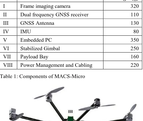
The prototype shown in Fig. 2 (including camera, stabilized gimbal, embedded PC, GNSS, IMU, antenna and power management) could be considered as autonomous payload and can be operated with different suited carriers (external power supply presumed). The current weight of MACS-Micro is about 1620g and it was carried by a remotely piloted octocopter for aerial survey (Tab. 1). The total takeoff weight was about 4890g.
ID Module Weight [g]
I Frame imaging camera 320
II Dual frequency GNSS receiver 110
III GNSS Antenna 130
IV IMU 80
V Embedded PC 350
VI Stabilized Gimbal 250
VII Payload Bay 160
VIII Power Management and Cabling 220
Table 1: Components of MACS-Micro
Figure 2: CAD model of mounted MACS-Micro
3. OPTICAL SENSOR CALIBRATION
3.1 Geometric Calibration
The frame imaging camera has been calibrated using a 3D calibration field with coded markers located at Beuth University of Applied Sciences, Berlin. Several ground control points (GCP’s) are attached to two facades in an inner courtyard (Fig. 3). They have been measured with highly accurate engineering surveying devices followed by a net adjustment. The standard deviation of each coordinate is 1mm in each dimension. Additional coded markers have been installed on the ground to achieve a homogeneous distribution of GCP’s for each image. The image acquisition was done at nine different locations at different distances, line of sights and height levels in relation to the calibration field. At each location 4 images with 4 different rotations (0°, 90°, 180° and 270°) around the line of sight axis had been recorded.
Figure 3: Test field at Beuth University of Applied Sciences
The parameters of interior orientation (IO) and exterior orientation parameters (EO) were calculated during a bundle block adjustment. The point measurement was done automatically due to the use of coded markers. The significant estimated parameters are:
- Principal point of autocollimation xH, yH
- Calibrated focal length cK and
- Radial-symmetric distortion coefficients k0, k1 and k2
Due to the usage of converging images the correlation between the IO parameters could be minimized. The highest correlation value was 15% between ck and k2.
Figure 4: Radial Distortion [µm] as function of radius [mm] (APO Xenoplan). Software used: Technet Pictran
A second calibration was done after the aerial survey. To avoid setup specific influences, the locations of the camera were chosen identical as in the pre-flight calibration process. The results of the post-flight calibration differ in a maximum of 0.15 pixels for principal point of autocollimation and 0.02 pixels for calibrated focal length (Tab. 2). No changes could be observed concerning the distortion parameters (Fig. 4).
Parameter Pre-flight value
Post-flight value
Diff (pre/post)
Diff in pixel xH [mm] -0.2130 -0.2123 -0.0007 0.15
yH [mm] 0.0866 0.0871 -0.0005 0.10
ck [mm] 24.4357 24.4356 0.0001 0.03
k0 0.0000 0.0000 0.0000 -
k1 -1.94E-04 -1.94E-04 4.20E-08 -
k2 3.52E-07 3.52E-07 -4.16E-10 -
Table 2: Results of pre- and post-flight calibration
3.2 Radiometric Calibration
A conventional dark signal non-uniformity (DSNU) [BECKER ET AL, 2008] and a simplified photo response non-uniformity (PRNU) have been measured to correct appearing lens vignetting, soil particles and fixed pattern noise distortions. The DSNU was gained at an ambient temperature of approximately 20°C. Five images have been captured per exposure time using 200us, 400us, 800us and 1600us. The AD converter offset of this CMOS chip in global shutter mode (KAC-12040C1) was calculated to 358DN with a standard deviation of 224DN. Both numbers include readout noise and suggest that the sensor tends to an increased sensor noise. The PRNU was acquired using a custom-built „natural light LED“ flat field by CSS2 (Fig. 5). The flat field achieves a color rendering index level (CRI) of 98 and is correlated to a color temperature of 5000 Kelvin. Several full-framed images have been captured in a dark room at same ambient temperature. For each exposure time the flat field was rotated thrice (0°, 30° and 90°). Following exposure times have been used: 100us, 250us, 500us, 1000us and 1500us.
The calculated offset- and factor-images were used to preprocess and adjust every image before further use.
Figure 5: Custom-built „natural white LED“ flat field with frame imaging camera during daylight
1 www.onsemi.com/pub/Collateral/KAC-12040-D.PDF (20.01.2016)
2
TH-224X1170W50 (custom-built LED flat field) www.ccs-grp.com/ledline/002.html (20.01.2016)
4. AERIAL SURVEY
The maiden flight was performed in the end of October 2015 at German Aerospace Center (DLR) campus in Berlin-Adlershof. The main test target was a building complex (30x30m) with a height of 12m and its surroundings. 39 GCP’s where marked within an area of 80x70m (19 GCP’s on the ground, 20 GCP’s on the roofs). All GCP’s have been surveyed with precise geodetic devices. The standard deviation of the GCP’s are 3mm in planimetry and 2mm in height.
The aerial survey was planned with following parameters in reference to the ground:
- Flight pattern cross (5x4 lines)
- Overlap in flight direction 90% - Overlap across flight direction 75% - Ground sampling distance (GSD) 1.1cm
This configuration (Fig. 6) results in an altitude over ground of 55m. The overlaps were reached by adjusting the RPAS speed (4m/s), frequency of image acquisition (1Hz) and distance between neighbouring flight lines (15m). The maiden flight was done with an octocopter following the alternating flight lines like it is common for airborne imaging flights. Thus parameters for conventional airborne flights could be used for post processing the navigation data to enhance the quality. Due to cloudy weather conditions an exposure time of 1.5ms was chosen to avoid ground smear and to prevent over- and under-saturations. A Siemens star and a 1951 USAF resolution test chart have been placed on the ground to estimate the true resolution.
Figure 6: Flight pattern with distribution of GCP’s
Figure 7: Resolution test charts (original resolution)
The post-processing of the raw images was done under consideration of the parameters for DSNU and PRNU (section 3.2) in bilinear debayering mode.
As expected the CMOS sensor shows an increased sensor noise due to global shutter mode. This caused artefacts in low illuminated areas which are unfavorable for tie point matching. The selection of longer exposure times, at the expense of image smear is recommended especially for unfavorable light conditions.
The raw GNSS and IMU data have been post-processed as well (with Novatel Inertial Explorer) including the differential correction data from SAPOS (a satellite positioning service of German land survey). The refined positions and attitudes were assigned to their corresponding image via GNSS timestamp.
5. PHOTOGRAMMETRIC EVALUATION
An aerial triangulation (AT) was calculated with the known interior orientation, the post-processed navigation data and a subset of 155 post-processed aerial images using a traditional photogrammetric software environment (Trimble Match AT). The point correspondences were determined with Least-Square Matching (LSM) algorithm. All GCP’s were measured manually in a first step followed by a refinement with LSM. Within the AT an accuracy of 0.4 GSD was obtained by checking 32 control points. This AT was based on a minimum of 7 control points (Tab. 3).
For the maiden flight the boresight angles and the rotation offsets between IMU- and camera coordinate system had to be calculated during the first AT. The shown IMU standard deviations are corrected with the determined boresight angles. In addition to the GNSS lever arms, which have been determined by a CAD-model of the system, the values have to be considered in future trajectory post processing.
Figure 8: RMSE values [m] of GCP and CP as shown in table 2 and 3
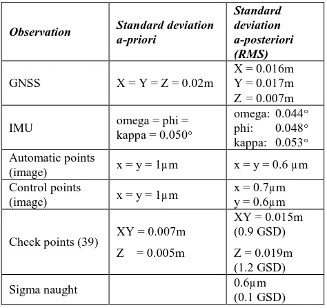
To demonstrate the achieved precision of the navigation data in combination with the metric camera a further AT without any control points were calculated. As shown in table 4 and figure 8, an accuracy of 0.6 GSD in plane and 1.2 GSD in height was obtained.
Observation Standard deviation
a-priori
Table 3: Results of AT with 7 control and 32 check points
Observation Standard deviation
a-priori
Table 4: Results of AT without control points (using GNSS/IMU observations only) and 39 check points
6. CONCLUSIONS
The present results based on the maiden flight indicate that the modular concept of MACS-Micro fulfills many of the above-mentioned key-specifications.
photogrammetry. The geometric stability of the industrial grade frame imaging sensor and lens has been verified by a pre- and post-flight-calibration and show no significant differences. The mentioned quality of both AT’s confirms the approach to combine an industrial grade camera with a high quality Dual-Frequency GNSS receiver and an industrial grade MEMS-IMU. Even the input of post-processed GNSS/IMU observations without ground control points will result in an AT where the object coordinates reache a precision of conventional terrestrial GNSS surveys. The applied validation workflow is the same as with common (large) airborne camera systems and is a further indicator that this prototype of MACS-Micro is applicable to RPAS photogrammetry. The chosen CMOS sensor shows an increased sensor noise in low illuminated areas which could be unfavorable for tie point matching. Due to the modular concept other sensors are applicable but the current frame imaging camera is really a sweet spot for RPAS less 5kg considering size, weight, performance, number of pixel and available industrial grade lenses.
The long-term stability (over weeks) will be verified in a separate investigation and will be issue of an upcoming publication. Another topic is to investigate and compare different software solutions (e.g. Agisoft, Pix4D & Trimble Match-AT) for this dataset.
7. REFERENCES
BRAUCHLE,J.,RÜTHER-KINDEL,W.,BERGER,R.,2014. MACS-TumbleCam - A Novel Approach for Aerial Oblique Imaging. Photogrammetrie, Fernerkundung, Geoinformation, 2014 (4), pp. 253-263. Schweizerbart Science Publishers, Stuttgart, Germany.
CRAMER, M., HAALA, N., ROTHERMEL, M., LEINSS, B. & FRITSCH, D., 2013. UAV-gestützte Datenerfassung für Anwendungen der Landesvermessung – das Hessigheim-Projekt. Publikationen der Deutschen Gesellschaft für Photogrammetrie, Fernerkundung und Geoinformation e.V. (DGPF), Tagungsband 22, pp. 450-469.
BECKER,H.N.,DOLPHIN,M.D.,THORBOURN D.O.,ALEXANDER, J.W. SALOMON, P.M., 2008. Commercial Sensor Survey. Radiation Testing Progress Report. Jet Propulsion Laboratory California, Institute of Technology Pasadena, California. JPL Publication 08-22 4/08.
HARWIN, S., LUCIEER, A., 2012. Assessing the accuracy of georeferenced point clouds produced via multi-view stereopsis from unmanned aerial vehicle (UAV) imagery. Remote Sensing, 2012 (4), No. 6, pp. 1573-1599.
GERMAN FEDERAL MINISTRY OF TRANSPORT AND DIGITAL
INFRASTRUCTURE,2014. Kurzinformation über die Nutzung von unbemannten Luftfahrtsystemen.
www.bmvi.de/SharedDocs/DE/Publikationen/LF/unbemannte-luftfahrtsysteme.pdf (01. Jan 2014).
LEHMANN,F.,BERGER,R.,BRAUCHLE,J.HEIN,D.,MEIßNER H., PLESS,S.,2011. MACS - Modular Airborne Camera System for
generating photogrammetric high-resolution products. Zeitschrift der Deutschen Gesellschaft für Geowissenschaften, 2011 (6), pp. 435-446. Schweizerbart Science Publishers, Stuttgart, Germany.
MARTIN,O.,MEYNARD C.,PIERROT-DESEILLIGNY M.,SOUCHON
J.-P., THOM CH., 2014. Réalisation d’une caméra photogrammétrique ultralégère et de haute résolution. Colloque Drones et moyens légers aéroportés d'observation, Montpellier, France, 24-26 Juin 2014, to be published in RFPT.
NEX, F., GERKE, M., REMONDINO, F., PRZYBILLA H.-J.,
BÄUMKER, M., ZURHORST, A., 2015. ISPRS Benchmark for Multi-Platform Photogrammetry. ISPRS Annals of the Photogrammetry, Remote Sensing and Spatial Information Sciences, Vol. II-3/W4, pp.135-142.
PRZYBILLA,H-J.,REUBER,C.,BÄUMKER,M.,GERKE,M.,2015. Untersuchungen zur Genauigkeitssteigerung von UAV-Bildflügen. Publikationen der Deutschen Gesellschaft für Photogrammetrie, Fernerkundung und Geoinformation e.V. (DGPF), Tagungsband 24, pp. 45-54.