EVALUATING THE GEOMETRIC SHAPE OF A FLYING PARAGLIDER
!
Klaus Hanke, Stefan Schenk
Surveying and Geoinformation Unit, University of Innsbruck, Austria [email protected]; [email protected]
Commission V, WG V/1
KEY WORDS: paraglider, close-range photogrammetry, geometric shape, data acquisition in flight
ABSTRACT:
This paper describes the photogrammetric approach to find the geometric shape of a paraglider. As its geometry is only available during the flight this had to be done under special conditions. The layout of the camera positions was limited by the strict safety of the pilot as well as a wind and flying situation that guarantees a stable geometry of the object for several minutes. The data acquisition was finally carried out in the area of Lake Garda and the pilot had the challenging task to handle the calibrated camera using a telescope arm in predefined positions during his flight. The evaluation of the 3D position of selected discrete points representing the paraglider’s shape was done by employing a bundle adjustment software and led to very satisfying results which were also proof of the stability of the paraglider during data acquisition as well as of the symmetry of the resulting shape.
Fig.1: Pilot’s view of the paraglider
1. INTRODUCTION
In this paper we discuss approaches for 3D measurements to achieve the geometric shape of paraglider wings represented by characteristic surface points (see Fig. 1 and Fig. 2) for quality control and prototype development as well as to elaborate a measurement workflow which suffices both cost and effort. The here presented case study was designed to research 3D measurement of paragliders in air in order to explore the possibility of reusing already existing paraglider conceptions as to create new innovative prototypes and/or future numerical studies. To investigate the potentials and limits of the described workflow, a number of test flights have been carried out exemplarily using an OzoneTM Mantra M4 (Fig. 1) and a Mantra R11 (Fig. 6) high performance competition paragliders which were at our disposal.
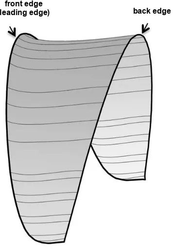
A paraglider generally consists of an upper and a lower hull part, which are connected by internal ribs in flight direction. They form a kind of channel for the air to float through the glider giving it its final wing-like shape and consisting of two layers of fabric; these are connected and supported by a number of ribs creating a row of narrow cells. The cells are left open at the leading edge so that air keeps coming in and inflates the wing which can thus reach its characteristic double-curved geometric shape. The wing's cross-section assumes a teardrop airfoil shape (see Fig. 8). Paraglider wings typically consist of non-porous materials such as ripstop polyester which prove especially resistant to tearing and stretching (Gulieri G., 2012; Toglia C. and Vendittelli M., 2010).
Lines (ropes) leading from the glider down to the pilot allow to steer and control the glider through change of position and shift of weight of the pilot’s body. All in all this construction is rather fragile and its shape depends very much on wind and streaming conditions as well as the pilot’s weight, position and attitude relative to the paraglider.
The evaluation of complex shapes is one of the regular tasks in photogrammetry (Bartos P. and Gregor V., 1994; Menna F. et al., 2009; Koelman, H.J., 2010). In this case study the task was to acquire the shape of a paraglider. It consists just of a very thin piece of fabric that gets its geometric shape only when air is streaming through the numerous chambers of the glider and this is merely the case when it is in motion that is when it is flying in the air. The shape is greatly affected by wind and local gusts which makes it a fairly time-critical task. This means that it is either possible to capture the shape simultaneously from different camera positions or to find a situation for the glider in which it does not or at least not significantly change its form. A complex multi-camera configuration for simultaneous photogrammetric 3D data acquisition is, however, only feasible from the ground, as its weight and size do not allow employing it during the flight. This also includes that the camera positions would pre-define the place for photographing without taking into account the wind conditions that are necessary for a stable and continuous form of the paraglider.
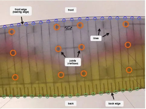
Fig. 2: Some points and curves of interest to be measured front
lines
joints (vertices)
back back edge
front edge (leading edge)
2. POSSIBLE CONCEPTS
Using sequentially taken images for photogrammetric purposes requires that the captured object doesn’t change during the whole measurement process. It was questionable whether it would be possible to reach such stable conditions during a flight: conditions in which the complete paraglider wing with a size of about 11.4 x 2.2 m does not change its fragile shape for several minutes. To proof this assumption was one of the targets of our research.
Basically, three possible situations for the 3D measurement were studied.
2.1 Ground-based approach
In the so-called ground-based approach, the pilot - standing on the ground - pulls the paraglider wing by hand from the ground into the air. Under favorable conditions and depending on the wind situation this leads to a 10-20 second lasting time gap in which the wing can be held quite stable for capturing.
There is, however, the possibility that in this artificially created situation the wing takes on a different shape as during a real flight. It is, in fact, very plausible that the missing weight of the pilot (as he is standing on the ground) and/or different atmospheric conditions near the ground may clearly influence the shape of the wing.
2.2 In-flight approach
The best chance for capturing the wing’s actual shape would be during the flight as such; however, already slight amounts of wind directly influence on the wing. Also side winds will result in a non-desirable asymmetrical wing shape. Furthermore, the measurements in this case have to be done by the pilot himself during flight, but mustn’t - under no condition - endanger the pilot’s safety.
Especially high performance competition paragliders are technically maxed out for highest speed and top speed stability, demanding remarkable flying skills from the pilot as the wing reacts highly sensitively and is responsive even to the smallest external impact. Real experts only can fly such a paraglider, and all measurement actions have to be well prepared and carried out with highest concentration and attention as every false step can directly lead to dangerous situations for the pilot.
Not only the measurements itself can cause risks; also the precision. In the case of challenging wind and air conditions the weight should be close to the top of the range.
To meet those requirements also when including the additional weight of the measurement equipment, some other non-vital tools were left on the ground during the here studied measurement flights. It has to be added that at all times it was carefully aimed first at reducing any impact on the balance and both the pilot’s and the paraglider’s freedom of movement, and, second, at minimizing the effect of additional weight on the shape of the wing.
2.3 Landing phase approach
Another possibility for capturing characteristic points on the wing is given during the landing phase. Just before touching the ground, the paraglider reaches a rather stable state in the air. The advantage of this approach is that high quality equipment can be positioned independently of its weight around the landing spot and can be operated by experts. We can, however, also in this case not assert whether or not the shape of the wing during the landing phase is equal to the state during normal flight. Furthermore, as the paraglider is in movement and the equipment is positioned at the ground, the right timing of the measurements might be problematic, but nevertheless technically manageable. Due to the fact that in most cases just one prototype paraglider is available, a repetition of the landing phase requires, however, a certain amount of time (typically several hours) or is not possible at all due to changing wind conditions over the day.
3. DATA ACQUISITION
Due to these reasons an efficient measurement workflow for capturing the shape of a paraglider wing during the actual flight was considered necessary. This implies that the capturing procedure has to be accomplishable by the pilot himself without any direct external assistance. One might think of a tandem flight during which a second person is available for that task; this, however, would once more result in a completely different weight level and, moreover, only be possible with certain paragliders (and not with high performance competition gliders like the one used in the case study).
After further research it turned out that in the Alps only a few areas can enable really stable flight conditions for several minutes; the pilot conducting the test flights suggested flying over Lake Garda, Northern Italy. During a sunny weather phase in the middle of August all conditions were considered to be perfect for our purposes and so the pilot embarked on a test flight from Monte Baldo. While crossing the lake enough time was found for the pilot to take images from a number of different positions, before then starting the turning maneuver at the other side of the lake.
3.1 Camera configuration and setup implementation
As mentioned above a first test flight was carried out at Lake Garda during which a few test images (see Fig. 1) were taken with a GoPro HD2 helmet camera (11 MPixel) in order to get an idea of the distances between the pilot and the wing (7.5 m – 8.5 m) as well as the achievable image and detail quality (see Fig. 2). It was found that the images looked promising, but it also suggested that the only possibility to capture the wing as a whole was from directly above.
For the photogrammetric evaluation of the three-dimensionally distributed characteristic points on the wing, however, not only a calibrated camera but also images from different locations around the pilot’s position are necessary. This leads to two basic approaches. First two cameras can be used in a stereo arrangement for taking the images simultaneously. As the wing seen from positions close to the pilot has an unfavorable shape for photogrammetric evaluations (the wing looks like a part of the sphere surface), the use of a very wide baseline for image acquisition is advisable.
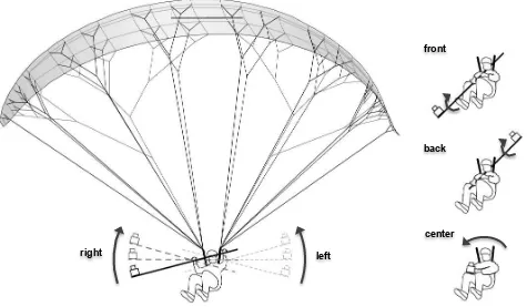
Fig. 3: Schematic view of the camera positions in flight direction
This, however, was considered to be rather problematic as the starting and landing phase with such a fixed camera arrangement can quickly result in dangerous situations. To avoid this, we decided in favor of just one calibrated camera (Nikon D200) with 12 MPixel, which was mounted on an aluminum telescope with a maximum length of 2.5 m. Given that 0.5 m were needed to hold the telescope, this led to an overall interaction space of 2 plus 2 m.
3.2 Scaling problem
Choosing a useful reference distance presented a further challenging task, because no reference - neither on the wing, nor on the lines - was usable; this was due to the fact that elastic materials act differently according to the varying dynamic air pressure on different parts of the wing during the flight. Due to the same reasons as described above, also using a fix baseline of camera positions (stereo camera setup) was not practicable (Luhmann T., Robson S., Kyle S., Boehm J., 2013).
To solve this problem an aluminum bar with a calibrated length had to be introduced into the configuration somewhere on or close to the wing’s lower surface. Such a bar can, however, be very dangerous because - if not positioned correctly - it might hinder the wing’s movement. It turned out that an ideal and secure spot for the application of the bar was in the center near the front side of the wing (see Fig. 4 and 7).
The bar was made of a black aluminum tube with a diameter of 20 mm. At both ends a 20 x 20 mm square aluminum profile with black markings was added for better visibility. This gave a total length of r = 2,021 mm as reference distance.
Using both ends of the aluminum profiles as reference distance for the 3D model scaling was, however, found to be tricky:
while the paraglider proved to be rather stable in the air, the bar as such did not and was weaving slightly due to wind streams. Only by manually sorting out those photographs in which the bar was moving, the reference distance could be determined with the same accuracy as the other points.
Fig. 4: Cross-section of the wing showing position of the aluminum bar defining the scale
3.3 Points of interest
Characteristic points for documenting the geometry of a paraglider wing are the joints of the single lines and the wing (see Fig. 5), which in the following are referred to as vertices (see orange marks in Fig. 3 and 7).
Of interest are, furthermore, points on the front as well as on the back edge of the paraglider (see blue and green marks in Fig. 3 and 7). Especially the front edge (air entrance) of the wing’s bottom shell is central as it has a considerable impact on the flight behavior and should ideally be captured together with the already mentioned joints of the lines and the wing.
As some vertices and points on the edges turned out to be difficult to mark from certain positions, black tape was used on the wing to increase their visibility (see Fig. 6).
aluminum bar
right left
front
back
center
Fig. 5: Vertex to be measured
3.4 Taking photographs vs. safety aspects
Each movement of the pilot with the telescope has, however, to be very carefully considered as any interference of the telescope and the lines, which have to be pulled for the flight maneuvers, could easily lead to a crash.
During the starting and landing phase the contracted telescope with the mounted camera is positioned on the pilot’s shoulder and between his legs. This was found to be an advantageous spot. In the air, radio-controlled images of the paraglider were taken from five different positions (see Fig. 3) by holding the extended telescope with the mounted camera (looking upwards) in the desired position: front, back, left, right and center. From each position an image series of about fifteen to twenty photos was taken. This was done by gradually turning the telescope in the desired direction as shown in Fig. 3. The images were taken by the pilot without him actually seeing them through the camera; however, after each image series it was possible to check the images on the display and eventually redoing them.
Finally, a set of 22 selected photographs (out of 93 total photographs) was used for photogrammetric evaluation. 3.5 Bundle adjustment
The orientation and evaluation was solved using the bundle adjustment software PhotoModeler™. The required characteristic points on the paraglider wing, such as joints between the single lines and the wing, and the actual edges of the paraglider (see Fig. 2) were determined. Especially the front edge (leading edge) was considered important due to its considerable impact on the flight behavior.
Finally, the measured points on its surface could approximate a satisfactory 3D surface model of the lower shell of the paraglider.
4. RESULTS AND EVALUATION
To evaluate the resulting 3D model, the generated text output of PhotoModelerTM as well as the corresponding 3D model in DXF file-format were analyzed in detail. This led to a number of results and findings regarding the quality of the measured points, additional reference distances, the planarity of cross-sections and overall symmetry.
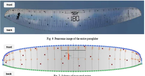
Figure 6 shows a panorama image generated out of five photographs taken from the position in the back (see Fig. 3). The asymmetry visible in the image is, however, only the result of a slightly skewed camera position and not due to the paraglider itself, which can be assumed to be rather symmetric (see Chapt. 4.4).
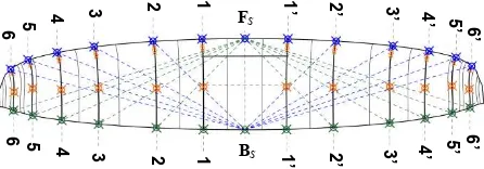
In total, 270 points were marked and referenced on 22 selected photographs, whereby 20 coded targets were used; moreover, 80 vertices as well as 87 plus 83 points on the front and back edge were marked manually (see Tab. 1). The scheme of all captured points is illustrated in Fig. 7 (not including points on the scaling bar).
Fig. 6: Panorama image of the entire paraglider
Fig. 7: Scheme of measured points
c1
c2 front
back
back front
r
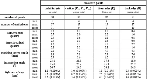
measured points
Tab. 1: Quality of measured points
4.1 Quality of measured points
By looking at the point quality table of PhotoModelerTM, the quality of measured points can be assessed. Especially the residuals, the precision vectors, the intersection angles and the tightness of the rays can give clues about good measurements. Tab. 1 summarizes the values regarding point quality separately for coded targets, vertices, front and back edge points. The corresponding colors of the targets, vertices and edge points in Fig. 3 and 7 are red, orange, blue and green.
Each point was referenced in at least four, maximum seventeen photos. The largest residual should possibly be below 3 pixels for projects with calibrated cameras. This quality requirement can be met by all of the measured points (max. 2.2 pixels < 3 pixels).
Looking at the precision vector lengths, a clear difference between automatically marked coded targets (max. 1.3 mm) and
manually marked points (max. 7.9 mm) becomes evident. This
difference emerges, however, primarily from the specific feature point characteristics and not so much from the marking method.
All coded targets and vertex points in this project were calculated with an intersection angle larger than 23.5°. Some points along the edges, however, are characterized by an angle of only 17.3° to 18.0°. These lower values result from the limited camera configuration when measuring the edges. Information about the quality of orientation and of a point’s sufficient overall quality of the project can be expected.
Summarizing these results it can be said that the project meets the requirements for a possibly good quality regarding the measured points in terms of (marking) residuals, precision and tightness of the rays. All values can be considered particularly remarkable taking into account that a paraglider is a highly flexible and fragile construct which is directly and constantly influenced by its environment.
4.2 Additional reference distances
As specified above, a fixed length aluminum bar with a length of r = 2,021 mm was employed (see Fig. 4 and 7) to solve the scaling problem. To get additional control over the model scaling, taking into account other reference distances (directly on the paraglider) was advisable.
It is generally known that wind, air, material, weight as well as other internal and external factors strongly affect the paraglider’s double-curved geometric shape during the flight. The wing itself consists of narrow cells attached to each other (see Fig. 6) which are inflated by air flowing in from the front. Hereby the width of each cell is directly related to the prevalent air pressure in and outside the wing. Defining the reference distances across one or more cells is therefore rather challenging or almost impossible, as the distances can’t be established and measured on ground.
Somewhat easier is the measurement of distances in flight direction along the cells as their length is less influenced by air pressure. Moreover, especially regions near the paraglider’s axis of symmetry (in the middle) are characterized by lower curvatures. Hereby the distances c1 and c2(see Fig. 7) could be measured on the ground as reference values with c1,ref = 496 ± 1 mm and c2,ref = 865 ± 1 mm. To simulate the elastic lengthening of the fabric due to air pressure it was, however, necessary to stretch the fabric manually with moderate tension.
The corresponding (straight) distances in the 3D model (after unconsidered curvature of the shape can possibly contribute to this error. Generally, however, the precision vector lengths as well as the tightness of the rays are somewhat higher than these differences.
As the determination of the correct model scaling was not the priority of this project, the results, however, do completely fulfill the requirements of the project.
4.3 Planarity of cross-sections
The paraglider consists of an overall of 82 cells separated by internal ribs made of the same fabric as the upper and lower part of the hull. Fig. 8 shows the shape of the internal rib of cross-section 3-3. The planarity of the fabric rib can’t be assumed in advance; nevertheless, even small deviations do indicate a good project quality.
Fig. 8: Cross-section 3-3
For a detailed study six ribs/cross-sections i-i with i = 1..6 on the left side of the paraglider were selected together with the six symmetrically chosen ribs/cross-sections on the right side labeled i’-i’ with i’ = 1..6 (see Fig. 9). Tab. 2 shows the distances of the point Vm,i out of the plane of the cross-section i -i as well as of Vm,i’ out of the plane of cross-section i’-i’. It can be seen that the maximum deviation is 2.6 mm, which is a fairly good value considering the overall accuracy of the
Tab. 2: Length and planarity of cross-sections
Fig. 9: Overview of the analyzed cross-sections
4.4 Evaluating symmetry
Ideally, the paraglider is forming a symmetric shape during the flight splitting the hull along the cross-section FS-BS (see Fig. 9) into a left and a right side. Several factors, however, can have minor or major influence on symmetry.
Supposed that the manufacturer, due to flying and safety reasons, constructed the paraglider completely symmetrically, also the lines have to be adjusted symmetrically. This may be done during a check-up of the line lengths executed at least every second year. Asymmetry could arise, however, due to an (almost natural) non-uniform airflow or even due to the asymmetry in the shape. The results are, however, promising, as the maximum difference between the left and the right side reaches a maximum of 6 mm at cross-section 3-3/3’-3’ only.
distance (mm)
Tab. 3: Comparison of control distances
To provide a realistic estimate regarding the symmetry of the whole paraglider, some spatial distances across the paraglider were considered, which are illustrated in Fig. 9. As Tab. 3 shows, the distances increase the further the considered points on the cross-sections are away from the axis of symmetry F S-BS. Furthermore, one can note that starting from cross-section 4-4 the distances on the left side are always smaller than those
Vm,3
on the right side (max. -27 mm). This suggests that there could be a systematic influence on the paraglider slightly changing its shape. It is obvious that differences not only arise due to a higher distance from the axis of symmetry, but also from the fact that the wingtips of the paraglider hull are much more sensible with regards to various internal or external factors.
We found out that the here analyzed paraglider didn’t have a completely symmetric shape during the measurement flight; as the deviations of the control distances are still within an acceptable range, however, overall symmetry can be assumed for our purposes. The final 3D model is shown in Fig. 10.
Fig. 10: Final 3D model of the paraglider’s lower surface
5. EXPERIENCES AND CONCLUSION
During this case study, photogrammetry has proved once more to be suited for the measurement of complex 3D shapes and to satisfy the project’s requirements.
A paraglider is a very fragile construction consisting of two layers of thin fabric inflated by air during the flight. This makes it fairly sensible to side winds and streaming conditions as well as to the pilot’s and the equipment’s weight, position and attitude. Only during flight 3D measurement can take place as just then the paraglider’s typical shape is given.
The use of a single calibrated camera on a telescope presented a valuable opportunity to capture the paraglider in the air, especially as a complex multiple-camera setup may not be applicable due to its additional weight and the necessary safety issues for the pilot.
Evaluation based on photogrammetric bundle adjustment software proved that the paraglider remained indeed stable during the complete data acquisition flight at Lake Garda. This showed that 3D measurement of flying paragliders is less time-critical than assumed. It is, however, important that the optimal
flying spot and time are chosen where ideal stable wind and streaming conditions are given.
The achieved results demonstrate that it is possible to attain high accuracy with both coded targets as well as manually selected vertex and edge points. This makes the here presented approach well suited for several related applications.
The scaling of the 3D model was established using a fixed length bar as reference distance. For safety reasons the bar, however, couldn’t be installed directly on the paraglider or its lines. Two short additional lines were mounted on the paraglider instead. This was necessary so that the paraglider was still able to move freely during the starting and landing phase as well as in case of emergency maneuvers.
During the evaluation process it turned out that the paraglider itself was very stable in the air, but the bar wasn’t. Some effort had to be put in sorting out photographs on which the bar was in motion. For the future, further research is thus advisable. Overall, we could prove that the presented workflow is not only suitable, but also safe for the pilot, cost-efficient and delivering satisfying results which can be used for both prototype development and quality control.
ACKNOWLEDGEMENT
The authors wish to thank TIS Techno Innovation South Tyrol, Bolzano for their cooperation and the initiation of the project.
REFERENCES
Bartos P. and Gregor V., 1994. Nontopographic applications using digital photogrammetry, Proc. SPIE 2252, Optical 3D Measurement Techniques II: Applications in Inspection, Quality Control, and Robotics, 276.
Gulieri G., 2012. Parachute-payload system flight dynamics and trajectory simulation. International Journal of Aerospace Engineering Volume 2012, Article ID 182907, 17 pages, March 2012.
Koelman H.J., 2010. Application of a photogrammetry-based system to measure and re-engineer ship hulls and ship parts: An industrial practices-based report. Computer-Aided Design, 2010. 42(8): p. 731-743.
Luhmann T., Robson S., Kyle S. and Boehm J., 2013. Close-Range Photogrammetry and 3D Imaging. De Gruyter, 2nd ed., ISBN 3110302691.
Menna F. et al., 2009. Digital Photogrammetry: A Useful Tool For Shipbuilding Applications. In Proceedings of the 13th Congress of International Maritime Association of Mediterranean, IMAM. 2009. Istanbul, Turkey.
Toglia C. and Venditte M., 2010. Modeling and motion analysis of autonomous paragliders. Technical report, Università di Roma “La Sapienza”, May 2010.
front edge
(leading edge) back edge