A FAST APPROACH FOR STITCHING OF AERIAL IMAGES
A. Moussa a,b,* , N. El-Sheimy a
a
Dept. of Geomatics Engineering, University of Calgary, Calgary, Canada (amelsaye, elsheimy)@ucalgary.ca
b
Dept. of Electrical Engineering, Port-Said University, Port-Said, Egypt
Commission III, WG III/5
KEY WORDS: Aerial Imagery, Image Stitching, Image Mosaicing, SIFT, Constrained Delaunay Triangulation
ABSTRACT:
The last few years have witnessed an increasing volume of aerial image data because of the extensive improvements of the Unmanned Aerial Vehicles (UAVs). These newly developed UAVs have led to a wide variety of applications. A fast assessment of the achieved coverage and overlap of the acquired images of a UAV flight mission is of great help to save the time and cost of the further steps. A fast automatic stitching of the acquired images can help to visually assess the achieved coverage and overlap during the flight mission. This paper proposes an automatic image stitching approach that creates a single overview stitched image using the acquired images during a UAV flight mission along with a coverage image that represents the count of overlaps between the acquired images. The main challenge of such task is the huge number of images that are typically involved in such scenarios. A short flight mission with image acquisition frequency of one second can capture hundreds to thousands of images. The main focus of the proposed approach is to reduce the processing time of the image stitching procedure by exploiting the initial knowledge about the images positions provided by the navigation sensors. The proposed approach also avoids solving for all the transformation parameters of all the photos together to save the expected long computation time if all the parameters were considered simultaneously. After extracting the points of interest of all the involved images using Scale-Invariant Feature Transform (SIFT) algorithm, the proposed approach uses the initial image’s coordinates to build an incremental constrained Delaunay triangulation that represents the neighborhood of each image. This triangulation helps to match only the neighbor images and therefore reduces the time-consuming features matching step. The estimated relative orientation between the matched images is used to find a candidate seed image for the stitching process. The pre-estimated transformation parameters of the images are employed successively in a growing fashion to create the stitched image and the coverage image. The proposed approach is implemented and tested using the images acquired through a UAV flight mission and the achieved results are presented and discussed.
1. INTRODUCTION
Aerial images have played an essential role for a wide variety of applications such environmental monitoring, urban planning and mapping, disaster assessment. The recent advancements of GPS and IMU units along with the successful designs of small aerial vehicles have enabled a huge variety of UAV systems with diverse capabilities. Such UAV systems offer increasing capabilities towards new applications that needs frequent visiting times, high resolution, highly portable, easily operated, and low cost solutions. The recent years witnessed an increasing volume of aerial images data collected by such UAV systems for different applications. Image mosaics are among the most important targeted products of an aerial imaging system where the individual acquired images during the flight mission is stitched together to offer a large field of view of the surveyed scene.
Image stitching/mosaicing has gained a lot of attention in many applications such as medical imagery (Can et al., 1999; Choe et al., 2006; Usmani et al., 2014), navigation (Lucas et al., 2010), and remote sensing (Turner et al., 2012; Wei et al., 2015). For constructing a stitched image, the transformations between the involved images have to be estimated based on overlapping areas between these images. Many approaches have been proposed to automatically find these overlapping areas and to model the transformation between images. Most of the developed image mosaicing methods adopt spatial domain matching techniques in either area-based or feature-based fashion. Few frequency based mosaicing methods have also
been proposed to solve the image mosaicing using frequency domain transforms such as Fast Fourier Transform (FFT) (Xie et al., 2003). In spatial domain area-based matching techniques, a window of an image is matched to another image using a similarity metric to find the correspondence between the images. Similarity metrics such as normalized cross correlation (Zhao et al., 2006), and entropy and mutual information (De Césare et al., 2008) have been employed in image mosaicing. Recently, the use of feature-based matching techniques has dominated the proposed mosaicing algorithms. Different image features have been successfully utilized in image mosaicing such as SIFT (Brown and Lowe, 2007; Jia et al., 2015; Liqian and Yuehui, 2010), Harris points (Zagrouba et al., 2009), and Speeded Up Robust Features (SURF) (Geng et al., 2012; Rong et al., 2009; Wang and Watada, 2015; Xingteng et al., 2015). According to the flight time, image acquisition frequency, and the required overlap, a typical UAV system acquires hundreds to thousands of images in one flight. The assessment of the achieved coverage and overlap of the acquired images of a flight mission is of great help to ensure successful product generation, correct decision and to save the time and cost of the further steps. This assessment is crucial to mitigate problems of unexpected imaging failures and the expected large angular variations between images at low altitude flights (Zhang et al., 2011). High camera rotations between adjacent images due to wind effects or stabilising platform inaccuracies can decrease the achieved overlap (Zhang et al., 2011), miss important information, and deteriorate the final product accuracy.
Stitching the flight captured images typically includes many underlying steps that take place after the acquisition of all images is completed. Extracting the points of interest of each image is the first step by many of the proposed approaches. Then, the extracted feature points are matched between images either globally or in a restricted search fashion such as in (Xiang et al., 2014). With the help of the matched points, the relative orientation between the captured images is calculated through a bundle adjustment procedure to find an optimal estimate of the camera rotations and displacements. Afterwards, the estimated Exterior Orientation Parameters (EOPs) are used to calculate the needed transformations of the images for the stitching process. Finally, the transformed images are stitched into a single image mosaic while blending of the different overlapped areas takes place to mitigate the radiance variations of the individual images and to offer a homogenous appearance of the final mosaic image. This typical procedure can take up to hours of processing time to construct the final mosaic image (Lin and Medioni, 2007; Xiang et al., 2014).
For a fast assessment of the achieved overlap between images, the typical processing workflow, that starts after the images acquisition completion and which includes a bundle adjustment step and a blending step, might not be the best option with respect to the processing time. A fast stitching of the acquired images can serve in evaluating the adequacy and completion of the gathered images and also can enable a correction action to be taken on proper time. A fast sub-optimal stitched image that does not employ globally estimated EOPs and does not blend the overlapped images can still be useful as an assessment tool to detect image acquisition and overlapping/coverage problems in a timely matter.
The main motivation of the proposed approach is to construct a fast stitched image to help as a preliminary assessment tool. The proposed approach exploits the initial knowledge about the images positions provided by the navigation sensors to enable matching image pairs before the images acquisition completion. The proposed approach also avoids solving for all the transformation parameters of all the images together to save the expected long computation time if all the parameters were considered simultaneously.
The approach adopts an incremental/sequential fashion that attempts to conduct calculations upon available inputs are ready. The points of interest of all the involved images are extracted using (SIFT) algorithm. Constrained Delaunay triangulation is conducted in an incremental fashion upon new image acquisitions to find suitable image pairs to be matched. This triangulation helps to match only the neighbor images and therefore reduces the time-consuming features matching step. Afterwards, the relative orientation between the matched images is estimated to help find the seed image for the stitching process. Then, the estimation of the transformation parameters of three photos, of the seed triangle, is conducted. Finally, the transformation parameters of the surrounding triangles are calculated successively in a growing fashion using the pair-wise transformations to create the stitched image and the coverage stitched image includes: the feature points extraction, the matching of the extracted points between the images, the
filtering of the matched points to remove the matches that do not fit the transformation model between the images, globally optimized estimation of the exterior orientation parameters of the camera at exposure times through bundle adjustment procedure, projection of the images into one single stitched images, and finally blending the overlapped areas to produce a visually homogeneous image.
In the proposed approach, some of the these steps are conducted upon availability of its input, and therefore the approach works in a per-image fashion until all the images are already acquired and ready to be stitched.
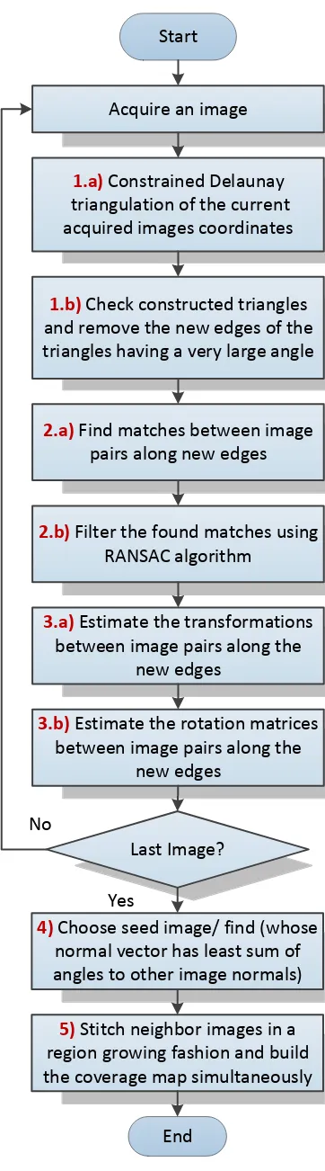
Figure 1 depicts the flowchart of the proposed approach that describes the main included tasks. For each recently acquired image, steps 1 to 3 are conducted and upon completion of the images acquisition the last two steps are taking place. The following subsections describe the details of each step.
2.1 Incremental Constrained Delaunay Triangulation
Instead of finding all the possible matches between all the flight images, the proposed approach attempts to find only the matches between the neighbour images. The flight height is typically kept constant as possible to preserve the utmost of the designed forward and lateral overlap ratios of the flight mission. 2D Delaunay triangulation is employed in the proposed approach to represent the neighbourhood of the acquired images. This triangulation is calculated based on the aerial vehicle horizontal coordinates obtained through the mounted navigation module. To enable the calculation of the triangulation before image acquisition completion, a constrained Delaunay triangulation (Chew, 1989; Lee and Lin, 1986) is conducted after each new image acquisition. The new resulting triangles after including each new image are checked to remove the undesirable ones that have an angle larger than 90o. Only the accepted edges are kept as constraints for the next triangulation and the rejected edges are removed. This technique helps to incrementally build a locally optimal triangulation of the images at the time of acquisition to serve as a neighbourhood representation. Such technique enables the matching process between neighbour images to take place before all images are acquired.
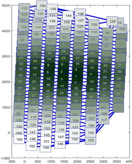
Figure 2 illustrates the obtained constrained triangulation after two different images acquisitions. Figure 2.a depicts the constrained triangulation after 25 images where the blue edges have been rejected as the underlying triangles have an angle larger than 90o. These rejected edges are removed and only the accepted edges in green are propagated to the next constrained triangulation. Figure 2.b shows the triangulation result after 76 images.
To illustrate the difference between the final result of the incremental constrained triangulation and the result of the regular triangulation using all images at once, Figure 3 depicts the final constrained triangulation after the completion of all images acquisition (in green), and the regular triangulation (in red). The regular triangulation has been intentionally shifted for illustration purpose. The figure shows a great deal of coincidence between the two triangulations with only few mismatched edges, and most of them are the long edges of the convex hull. This high coincidence reveals the capability of the proposed incremental constrained Delaunay triangulation scheme to significantly approximate the final triangulation while being constructed incrementally before the completion of the images acquisition.
Acquire an image
1.a)
Constrained Delaunay
triangulation of the current
acquired images coordinates
1.b)
Check constructed triangles
and remove the new edges of the
triangles having a very large angle
2.a)
Find matches between image
pairs along new edges
2.b)
Filter the found matches using
RANSAC algorithm
3.a)
Estimate the transformations
between image pairs along the
new edges
3.b)
Estimate the rotation matrices
between image pairs along the
new edges
Last Image?
No
4)
Choose seed image/ find (whose
normal vector has least sum of
angles to other image normals)
5)
Stitch neighbor images in a
region growing fashion and build
the coverage map simultaneously
Start
End
Yes
Figure 1. Flowchart of the proposed approach
Figure 2.a) Triangulation after 25 images (valid edges in green, rejected edges in blue)
Figure 2.b) Triangulation after 76 images (valid edges in green, rejected edges in blue)
Figure 3. Final result of the incremental triangulation (in green) and the regular triangulation shifted (in red)
2.2 Feature Points Extraction and Matching
For each recently captured image, the features points of this image are extracted using SIFT approach. The recently accepted edges of the last constrained triangulation after this image acquisition represents image pairs that have to be matched together. The image pair of each recently accepted triangulation edge is matched using the feature descriptors. This matching is refined to remove outlier matches using RANSAC algorithm (Fischler and Bolles, 1981). The RANSAC algorithm has been used to iteratively fit a fundamental matrix using the normalized
eight-point algorithm (Hartley and Zisserman, 2003) and exclude the outlier matches. With the help of the intrinsic parameters of the camera, the essential matrix is decomposed to obtain the relative orientations between the matched images. Furthermore, the homography transformation between the image pair is also computed to serve in the stitching process. Figure 4.1 shows the matching between two sample images with the inlier matches in yellow and the rejected outlier match in red. Figure 4.b depicts the calculated relative orientations between the two images.
Figure 4.a) Inlier, outlier matches between two sample images
4.b) Relative orientation between images
2.3 Incremental Stitching
The final stitching step can be conducted anytime when needed between the recently acquired and processed images or alternatively be postponed to the end of the image acquisition when all images are available. The proposed stitching procedure adopts an incremental scheme where the neighbours of the seed image are stitched in a region growing fashion one by one to the stitched image. In other words, all images are to be projected onto the seed image plane. The previously computed transformations between neighbour images are employed during this incremental stitching which renders the computation to be a straight forward projection of images. First, using the shortest connected edge to the seed, the closest neighbour image to the seed is found and projected into the seed plane without projecting the overlapped area. The one or two triangles adjacent to this edge are scheduled for inclusion in the stitching process. Each scheduled triangle indicates a new image to be registered that can be stitched using either one of two previously estimated transformations to the other two images of the triangle. Upon the stitching of this new image, the two edges between this image and the other two images of the triangle are used to schedule new triangles for inclusion. This process iterates until all triangles of the last constrained Delaunay triangulation are scheduled and processed.
Since the employed transformations have been estimated based only on image pairs with considering a global optimization procedure such as bundle adjustment, the registration errors are expected to increase at the farther images as the individual registration errors accumulate.
Seed images can be chosen, upon need, to be a specific image in order to obtain a more accurate mosaic image for assessment at this location. Such scenarios might arise when a specific area requires high surveillance attention or requires higher mapping
accuracy. The closest image to the center of the surveyed area can be used as a random seed image as the propagated error with such configuration is expected to expand uniformly in all directions.
Alternatively, the seed image can be chosen to be the one whose normal vector has least sum of angles to other image normal vectors. This choice will reduce the probability of highly tilted projection of images if a randomly selected seed point was highly tilted with respect to the other images. The previously estimated relative orientations between the neighbour images can be used to find the angles between normal vectors of the images. The seed image is found using an exhaustive search. Figure 5 illustrates the region growing sequence of images stitching, the darker labels represent the close images to the seed image (numbered as 1) which are processed earlier, and the light colored labels represent the farther images that have been processed later. The numbers of labels represent the stitching sequence of images.
Figure 5. The region growing sequence of images stitching
3. RESULTS AND DISCUSSION
The proposed approach has been implemented and tested on a data set of aerial images provided by National Cheng Kung University, Tainan. This data set has been acquired using a fixed wing UAV over around 3 km x 3 km area in Taiwan. The platform is equipped with a GPS/INS module and EOS 5D Mark II camera. The flight height was about 600 m above ground. A subset of 152 images has been used to test the implemented approach.
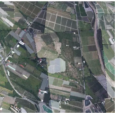
Figure 6 shows the stitched image using all the included images where the seed image was chosen to be the closest to the scene center. The center area of the stitched image, which is close to the seed image, exhibits a visually smooth stitching performance, while the boundary areas exhibit noticeable stitching errors due to the error propagation effect.
The obtained stitched image offers a complete view of the surveyed scene that can help perform a fast assessment of the image acquisition conditions and can also help decision makers to take actions in a timely manner.
Figure 6. Stitched image
Figure 7 depicts an enlarged view of an off-center area (bounded in yellow) in Figure 6 to illustrate the stitching performance beyond the center area. The image exhibits significant intensity variations in many areas due to the lack of intensity blending. Such blending has been ignored in the proposed approach to save its computation time as the main purpose is to offer a fast mosaic for rapid assessment. Many features have been adequately stitched such as the road at the upper right area and many others have deviated such as the lower part of the same road.
Figure 7. Enlarged view of the bounded area in Figure 6
Figure 8 shows the computed coverage map of the scene which indicates the number of overlaps over each area of the scene. The map exhibits a similar pattern to the adopted rows and columns flight pattern. Such map can be easily employed to detect if the overlap requirements have been met and to localize the areas that should be addressed.
Figure 8. Coverage map
CONCLUSIONS
This paper proposes a fast and suboptimal stitching approach that construct a single overview stitched image and a coverage map using aerial images. To reduce the processing time needed by typical stitching algorithms, the initial knowledge about the images positions provided by the navigation sensors are used to help solve for image transformations in a pair-wise local fashion and therefore avoids solving for all the transformation parameters of all the images simultaneously. An incremental constrained Delaunay triangulation of image’s coordinates has been conducted to build a locally optimized Delaunay triangulation that represents the neighborhood of each image. This triangulation helps to match only the neighbor images to cut the processing time. The stitching process starts at the seed image and continues in region growing fashion to project the neighbours into the stitched images sequentially. The proposed approach is tested using the images acquired through a UAV flight mission and the constructed stitched image offers a complete view of the scene along with a coverage map describing the overlap achieved between images.
ACKNOWLEDGEMENTS
This work was supported by Dr. Naser El-Sheimy research funds from NSERC and Canada Research Chairs programs. The authors would like to acknowledge Dr. Kai Wei form the National Cheng Kung University, Tainan, Taiwan for providing the test data set.
REFERENCES
Brown, M., Lowe, D.G., 2007. Automatic panoramic image stitching using invariant features. International journal of computer vision 74, pp. 59-73.
Can, A., Stewart, C.V., Roysam, B., 1999. Robust hierarchical algorithm for constructing a mosaic from images of the curved human retina, IEEE Computer Society Conference on Computer Vision and Pattern Recognition.
Chew, L.P., 1989. Constrained delaunay triangulations. Algorithmica 4, pp. 97-108.
Choe, T.E., Cohen, I., Lee, M., Medioni, G., 2006. Optimal global mosaic generation from retinal images, 18th International Conference on Pattern Recognition, 2006.IEEE. pp. 681-684.
De Césare, C., Rendas, M.-J., Allais, A.-G., Perrier, M., 2008. Low overlap image registration based on both entropy and mutual information measures, OCEANS2008. IEEE, pp. 1-9.
Fischler, M.A., Bolles, R.C., 1981. Random sample consensus: a paradigm for model fitting with applications to image analysis and automated cartography. Communications of the ACM 24, pp. 381-395.
Geng, N., He, D., Song, Y., 2012. Camera image mosaicing based on an optimized SURF algorithm. TELKOMNIKA Indonesian Journal of Electrical Engineering, 10, pp. 2183-2193.
Hartley, R., Zisserman, A., 2003. Multiple view geometry in computer vision. Cambridge university press.
Jia, Y., Su, Z., Zhang, Q., Zhang, Y., Gu, Y., Chen, Z., 2015. Research on UAV Remote Sensing Image Mosaic Method Based on SIFT. International Journal of Signal Processing, Image Processing and Pattern Recognition, 8(11), pp.365-374.
Lee, D.-T., Lin, A.K., 1986. Generalized Delaunay triangulation for planar graphs. Discrete & Computational Geometry 1(3), pp. 201-217.
Lin, Y., Medioni, G., 2007. Map-enhanced UAV image sequence registration and synchronization of multiple image sequences, IEEE Conference on Computer Vision and Pattern Recognition. IEEE, pp. 1-7.
Liqian, D., Yuehui, J., 2010. Moon landform images fusion and Mosaic based on SIFT method, International Conference on Computer and Information Application. IEEE, pp. 29-32.
Lucas, A., Christo, C., Silva, M.P., Cardeira, C., 2010. Mosaic based flexible navigation for AGVs, IEEE International Symposium on Industrial Electronics, IEEE, pp. 3545-3550.
Rong, W., Chen, H., Liu, J., Xu, Y., Haeusler, R., 2009. Mosaicing of microscope images based on surf, 24th International Conference on Image and Vision Computing New Zealand, IEEE, pp. 271-275.
Turner, D., Lucieer, A., Watson, C., 2012. An automated technique for generating georectified mosaics from ultra-high resolution unmanned aerial vehicle (UAV) imagery, based on
structure from motion (SfM) point clouds. Remote Sensing 4, pp. 1392-1410.
Usmani, D., Ahmad, T., Akram, M.U., Danyal Saeed, A., 2014. Fundus image mosaic generation for large field of view, 14th International Conference on Hybrid Intelligent Systems (HIS), IEEE, pp. 30-34.
Wang, J., Watada, J., 2015. Panoramic image mosaic based on SURF algorithm using OpenCV, 9th International Symposium on Intelligent Signal Processing, IEEE, pp. 1-6.
Wei, L., Shi, J., Huang, X., Ding, H., 2015. An aerial remote sensing image's mosaic approach using multi-layer wavelet fusion based on structure similarity, Ninth International Symposium on Multispectral Image Processing and Pattern Recognition. International Society for Optics and Photonics, pp. 981507-981508.
Xiang, R., Sun, M., Jiang, C., Liu, L., Zheng, H., Li, X., 2014. A method of fast mosaic for massive UAV images, SPIE Asia Pacific Remote Sensing. International Society for Optics and Photonics, pp. 92603-92609.
Xie, H., Hicks, N., Keller, G.R., Huang, H., Kreinovich, V., 2003. An IDL/ENVI implementation of the FFT-based algorithm for automatic image registration. Computers & Geosciences, 29, pp. 1045-1055.
Xingteng, J., Xuan, W., Zhe, D., 2015. Image matching method based on improved SURF algorithm, IEEE International Conference on Computer and Communications, IEEE, pp. 142-145.
Zagrouba, E., Barhoumi, W., Amri, S., 2009. An efficient image-mosaicing method based on multifeature matching. Machine Vision and Applications, 20, pp. 139-162.
Zhang, Y., Xiong, J., Hao, L., 2011. Photogrammetric processing of low‐altitude images acquired by unpiloted aerial vehicles. The Photogrammetric Record, 26, pp. 190-211.
Zhao, F., Huang, Q., Gao, W., 2006. Image matching by normalized cross-correlation, IEEE International Conference on Acoustics, Speech and Signal Processing, IEEE, pp. II-II.