DETECTION AND COMPENSATION OF BAND-TO-BAND REGISTRATION ERROR
FOR MULTI-SPECTRAL IMAGERY CAUSED BY SATELLITE JITTER
Ying Zhu a, Mi Wang a*, Quansheng Zhu a , Jun Pan a
a
LIESMARS, Wuhan University, No.129 Luo Yu Road, Wuhan, China- [email protected], [email protected], [email protected], [email protected]
KEY WORDS: Satellite Jitter Detection, Error Compensation, Band-to-band Registration, Accuracy Evaluation, Multi-spectral Image
ABSTRACT:
Satellite jitter has become a more and more important factor which affects the quality of imagery products with development of the high resolution satellite. This paper focused on analyzing the impact on multi-spectral image caused by satellite jitter and proposed a jitter detection and compensation method to improve the band-to-band registration efficiently when jitter exists without observation by attitude sensor. Firstly, the design of multi-spectral camera and the mainstream band-to-band registration method is introduced to explain factors influencing the registration accuracy. As one of factors, satellite jitter is an unexpected satellite movement and do have impact on registration on both across and along track but easy to be ignored for the lack of high frequency and accuracy attitude data. So next the jitter detection and compensation method is proposed, in which there are six main steps to achieve the analysis of registration accuracy with and without jitter and improvement of registration accuracy after compensation when the jitter cannot be ignored. Finally, three sets of multi-spectral images of ZY-3 were used to verify the proposed method. As a result, the error caused by satellite jitter was suppressed efficiently from 0.2pixels to 0.02pixels and registration accuracy (RMSE) was improved from 0.32 pixels to 0.11 pixels by the proposed method. The results indicate that the proposed method can detect and compensate the distortion of multi-spectral image caused by satellite jitter accurately and efficiently.
* Corresponding author. This is useful to know for communication with the appropriate person in cases with more than one author.
1. INTRODUCTION
Multi-spectral camera which can capture three or more bands of imagery is one of the most important imaging payloads on optical satellite, always coupling with panchromatic camera together, such as the familiar remote sensing satellites Geoeye-1, IKONOS, ZiYuan-3(ZY-3), etc. Most remote sensing images are obtained using push-broom scans by the coupling of line scans in one dimension and satellite movements in the vertical dimension (Iwassaki, 2012). For multi-spectral camera, the design is more complex because there are several bands on the focal plane. In most situations, the charge-coupled devices (CCDs) of multiple bands are placed in parallel on focal plane at a certain distance so that the different bands capture the same point at different times. Under the influence of satellite vibration, terrain relief and so on, two bands cannot be co-registered by a parallel shift and this leads to a band-to-band registration problem in pre-processing. The registration result will directly influence the further applications such as data fusion, change detection, spectral signature based classification, etc. So automatic band-to-band registration of multi-spectral image is the most critical pre-processing requirement and the accuracy of band-to-band registration is an important parameter of image product quality for multi-spectral image data.
Many researchers have made great efforts to find the best way to realize band-to-band registration with high accuracy and low time cost. In general, the existing band-to-band registration method can be categorized into two classes: (1) method based on image space, and (2) method based on object space. The image-based method can be understood as image matching method and its core is based on the ideal of tiny facet
differential rectification. There are four basic steps which in turns are 1) feature points extraction, 2) sub-pixel level image matching, 3) construction of the tiny facet and 4) the tiny facet differential rectification (Pan, et.al, 2011). The image-based method is a geometry-independent method but dependent on the accuracy and reliability of image matching and time-consuming in some degree because of sub-pixel level image matching. Object-based method is a geometry-dependent method and based on the ideal of geolocation consistency between two bands according to the rigorous geometric imaging model (Wang, et.al, 2013; Jiang, et.al, 2014). Once the high accuracy geometric relationship between two bands is established, the registration process becomes re-sampling processing without image matching. So the object-based method is more time-efficiency and reliable than image-based method especially for the desert and sea areas. But its registration accuracy directly relies on the accuracy of the geometry imaging model of different bands. High accuracy geometric model can be guaranteed by elements of interior orientation, exterior orientation and elevation model provided with high accuracy, which makes the registration accuracy better than 0.3 pixels (Root Square Mean Error, RMSE) (Wang, et.al, 2013; Jiang, et.al, 2014). So the object-based method is the first choice for band-to-band registration.
distortion caused by satellite jitter had been found in orthographs of The Advanced Spaceborne Thermal Emission and Reflection Radiometer (ASTER) and QickBird (Ayoub, et.al., 2008). The Advance Land Observing Satellite (ALOS) of Japan was also reported that the satellite jitter had impact on the fitting accuracy of Rational Polynomial Coefficients (RPCs), which is the geometry model in common use (Sultan, et.al., 2008). So it is necessary to investigate the satellite jitter detection and compensation method to improve the geometric accuracy of satellite images. In this paper, we focus on how satellite jitter influences the registration accuracy of multi-spectral image with parallax observation and how to detect and compensate the error caused by satellite jitter without attitude data accurately and efficiently.
2. MULTI-SPECTRAL IMAGE BAND-TO-BAND
REGISTRATION
2.1 Multi-spectral Camera Onboard HROS
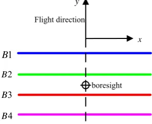
Multi-spectral camera onboard HROS has four or more bands of CCDs, which always are placed in parallel on focal plane with certain distance, shown in Figure 1. Such kind of design is applied in many in-fight satellites, like ASTER, IKONOS, OrbView-3, ZY-3, etc. The distance between bands makes different bands capture different scene at the same time. The back band on the focal plane always follows the front one, capturing the same scene at different times with a time lag. So the raw multi-spectral image is disarranged. Band-to-band registration becomes the basic and critical pre-processing for fowling processing and applications.
1
Figure 1. Design of multi-spectral camera onboard HROS
2.2 Object-based Band-to-band Registration Model
The object-based band-to-band registration method makes full use of the geometrical imaging relationship between bands and dispenses with image matching. Taking two bands (named B1 and B2) as example shown in Figure 2, the object point P is imaged successively on B1 and B2 as p1 and p2, respectively, at different time with the time lagΔt.
According to rigorous geometry imaging model of space-borne camera (Poli, 2007; SPOT, 2012), the geometric relationship between bands can be established as equation (1).
1 2 RBS = mounting matrix of camera
R(t1), R(t2) = satellite attitude matrix at t1,t2
(a) (b)
Figure 2. Geometrical imaging relationship between bands (a) in perspective, (b) in plan (Wang, et. al., 2013)
Once the relationship is established, the band-to-band registration becomes re-sample processing.
2.3 Registration Accuracy Analysis
In order to ensure the equation (1) setting up, the camera in-flight calibration should be done so that there is an accurate pointing of view. Besides, the terrain relief also should be considered and high accuracy digital elevation model (DEM) should be used to have good intersection accuracy. And as the important exterior orientation element, the attitude data is also the key to construct the registration model. Wang (2013) had deep analysis on CCDs relative distortion calibration and topography relief factor but ignore the attitude fluctuation factor because the distance is very short so that the attitude can be thought to be steady and the attitude data provided is smooth in fact. What’s more, the registration accuracy (RMSE) is less than 0.3 pixelswhen satellite doesn’t have jitter or the satellite jitter is very micro, which can satisfy the requirement of following applications. But when satellite has greater vibration, the influence will be obvious and cannot be ignored. And the attitude sensor onboard satellite cannot follow the sampling frequency of push broom camera. In the time lagΔt, if there were satellite jitter or pointing fluctuation, they will directly increase distortion between bands while the attitude sensor is not sensing it. So the distortion caused by jitter would still exist after registration.
3. DETECTION AND COMPENSATION OF
JITTER-CAUSED REGISTRATION ERROR
3.1 Jitter Impact Analysis
Satellite jitter, a kind of unexpected satellite movement, can be understood as the attitude fluctuation error combined by one or more harmonic components and expressed by following mathematical formula (Chen et. al., 2001).
1
i
f = frequency of attitude fluctuation indexed with i
mi
ϕ = amplitude of attitude fluctuation indexed with i
i
ϕ = initial phase of attitude fluctuation indexed with i i = the number of the harmonic component
Multi-spectral camera onboard HROS uses four or more push broom imaging linear array CCDs as the receiving device. The sampling frequency of the CCD is very high, e.g. 1250 Hz with 5.8 m Ground Sampling Distance (GSD) at 500 km orbit and it will increase with the improvement of the spatial resolution. So it is very sensitive to the micro-vibration of the satellite platform. And for multi-spectral image, the distance of different bands will change with the satellite jitter while the attitude sensor cannot observe it because of the limitation of its frequency and accuracy. The unmeasured satellite attitude fluctuation error can be divided into two parts: rolling fluctuation (ϕroll( )t ) and pitching fluctuation (ϕpitch( )t ), causing
Figure 3. Band-to-band registration error caused by rolling fluctuation (a) and pitching fluctuation (b)
From the Figure 3, it is obvious that the band-to-band registration error caused by satellite jitter is determined by the attitude fluctuation at t and t+ Δt time jointly and the impact is basically the same for every pixel in the same scan line.
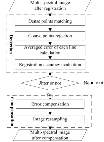
3.2 Jitter Detection and Compensation
The registration error caused by satellite jitter is still remained after registration using object-based method when satellite jitter exists while attitude data don’t contain it. So it is necessary to detect the uncorrected bias and judge the impact to registration accuracy and compensate the error if it cannot be ignored. This paper proposes a dense points matching based jitter detection and compensation method for multi-spectral image. There are six main steps in the whole flow chart shown as Figure 4.
Figure 4. The flow chart of jitter detection and compensation
3.2.1 Dense Points Matching: Take every pixel or pixel at a certain distance in sample direction as detection candidate point to ensure the sample points distribute evenly and sufficiently. And correlation matching and least squared matching (Gruen, 2012) is successively applied to obtain corresponding points with sub-pixel accuracy between two bands.
3.2.2 Coarse Points Rejection: Corresponding points whose coordinate differences are beyond the threshold value will be detected and removed. The threshold is determined by RMSE of each line and varies by different line. Here, we set the threshold as three times of RMSE.
3.2.3 Averaged Error of Each Line Calculation: After coarse point rejection, the average of coordinate differences of corresponding points in each line is calculated as the estimated error caused by satellite based on the ideal that the impact is basically the same for every pixel in the same scan line. The registration error across track (Δx u( )) and along track (Δy u( )) is calculated by formula (3).
, and in line direction indexed with u, k
k = point number
Vu = total number of points in line u
3.2.4 Registration Accuracy Evaluation: The registration accuracy then can be evaluated using the dense points by formula (4).
Where N = total number of image lines and other parameters have the same meaning as formula (3).
3.2.5 Error Compensation: Once the averaged error of each line is obtained, the error curve with the scan line can be drawn and the amplitude and frequency of the curve can be obviously observed when the satellite jitter exists. Otherwise, the value of the curve is random, which indicates there isn’t satellite jitter. When the amplitude cannot be ignored and the RMSE is beyond the required index, compensation should be done to improve the band-to-band registration. As the error of each line caused by jitter has been estimated by formula (3), the corrected coordinates is the sum of original coordinates and error.
ˆ ( )
3.2.6 Image Resample: When the new coordinates is calculated, the digital number (DN) value is obtained by interpolation, such as bilinear interpolation, bicubic convolution and so on.
4. EXPERIMENTS AND ANALYSIS
4.1 Datasets
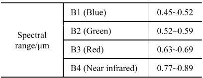
ZY-3, launched on January 9th 2012, is the first civilian high resolution stereo mapping satellite of China. The multi-spectral camera (hereafter referred to as “MUX”) onboard ZY-3 adopts design shown in figure 1. Four bands which are blue, green, red and infrared red, are parallel to each other with about 2 mm distance to the adjacent one. The GSD of the multi-spectral image is 5.8 m. The spectral ranges of the payload are shown as table 1.
Table 1. Spectral range of MUX onboard ZY-3
Spectral range/μm
B1 (Blue) 0.45~0.52
B2 (Green) 0.52~0.59
B3 (Red) 0.63~0.69
B4 (Near infrared) 0.77~0.89
Three sets of MUX data are used to analyze the registration accuracy with and without satellite jitter and before and after compensation when jitter exists. The information of the datasets is listed in table 2.
Table 2. Experiments datasets information
No. Imaging
The size of above images is 8824×9715.
Following the flow chart of jitter detection and compensation, firstly the jitter should be detected using MUX images after band-to-band registration by object-based method to figure out which image has residual error caused by satellite jitter and which image has not. Then the registration accuracy of MUX images is evaluated by statistical indexes such as RMSE, average error, etc. Finally, the residual error caused by satellite jitter is compensated by proposed method and re-evaluation is conducted to verify the band-to-band registration accuracy after compensation.
In the experiment, we chose B2 (green) and B3 (red) band as the combination to conduct experiments because these two bands have much more similar spectral characteristics which can increase the image matching accuracy. And what’s more, they are adjacent to each other, so this combination is more sensitive to the satellite jitter in shorter time than others.
4.2 Jitter Detection
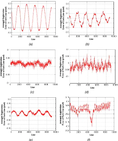
Firstly, the image matching pixel by pixel was done to obtain the registration error of each pixel between B2 and B3 and the registration errors on the same scan line were averaged as the estimation error caused by satellite jitter. Error in sample direction is corresponding to rolling fluctuation and error in line direction is corresponding to pitching fluctuation. The detection results were shown in Figure 5 and 6.
It is obvious that detection results of three datasets are different with each other. There is periodic error remained in dataset 1 in both sample and line direction and the frequency in both directions is basically same about 2000 lines but the amplitude is different, about 0.25 pixels in sample direction and 0.15 pixels in line direction. Dataset 3 only has micro periodic error in sample direction about 0.02 pixels with about 2000 lines period and there is a sudden jitter at about 5000 line in flight direction, causing 0.2 pixels error. The detection results of dataset 2 are random in both directions. So it is indicated that dataset 1 has more obvious periodic jitter of rolling angel and pitching angle, dataset 3 has smaller periodic jitter of rolling angel and a sudden jitter of both angels and dataset 2 has no jitter.
It’s noted that the jitter detection curves have different levels of micro offsets from the origin (zero) in both sample and line direction for these three datasets. This may be the residual error of interior elements and external elements.
(a) (b)
(c) (d)
(e) (f)
(a) (b) (c)
(d) (e) (f)
(g) (h) (i)
Figure 6. Error map of jitter detection. (a), (d), (g) are original images of dataset 1, 2, 3;
(b), (e), (h) are error maps in sample direction of dataset 1, 2, 3; (c), (f), (i) are error maps in line direction of dataset 1, 2, 3.
4.3 Accuracy Evaluation
In order to explain the impact of the satellite jitter further, the B2-B3 registration accuracy of three datasets was calculated by formula (4) and listed in table 3.
Table 3. B2-B3 registration accuracy
Dataset
No.
AE (pixel) RMSE (pixel)
x y x y total
1 -0.0019 -0.0285 0.2773 0.1772 0.3292
2 -0.0380 0.0138 0.1134 0.1207 0.1656
3 -0.0193 0.0148 0.0774 0.1008 0.1271
As expected, the RMSE in total of dataset1 is biggest and beyond the requirement of accuracy because of the uncorrected error caused by jitter. And dataset 2 and 3 have similar registration accuracy around 0.1 pixels, fully satisfied with requirement of application.
4.4 Error Compensation
(a) (b)
(c) (d)
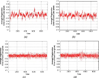
Figure 7. The jitter detection curve after compensation, (a), (c), are error curves in sample direction of dataset 1, 3; (b) (d) are error curves in line direction of dataset 1, 3.
Compared with Figure 5, Figure 7 shows that the periodic error has been suppressed efficiently from 0.25 pixels in sample direction, 0.15 pixels in line direction (dataset 1) and 0.025 pixels (dataset 3) to 0.02 pixels (both datasets) in random distribution after compensation. And the error caused by sudden fluctuation in line direction of dataset 3 is also disappeared.
4.5 Accuracy Re-evaluation
In order to analyze the compensation effect further, the B2-B3 registration accuracy of dataset 1 and 3 is re-evaluated, listed in table 4. Compared with the results in table 3, the accuracy of dataset 1 is greatly improved from 0.4 pixels to 0.1 pixels in total but the accuracy of dataset 3 keeps the same as before compensation which indicates the error caused by jitter is so small as to be ignored.
Table 4. B2-B3 registration accuracy after compensation
Dataset
No.
AE (pixel) RMSE (pixel)
x y x y total
1 -0.0059 0.0008 0.0832 0.0810 0.1161
3 0.0013 0.0032 0.0737 0.1034 0.1270
Above all, the satellite jitter has impact on the band-to-band registration accuracy in some degree. The detection and compensation method proposed by this paper is efficient and applicative to improve the registration accuracy when jitter cannot be ignored.
5. CONCLUSION AND FUTURE WORK
In this paper, we analyze the influence of satellite jitter to band-to-band registration accuracy for multi-spectral images onboard HROS. The comparison of registration accuracy with and without jitter was done by using three sets of images of MUX, the multi-spectral camera on ZY-3. The results shown that jitter would cause registration error in different degrees. When the amplitude of jitter is small enough, the impact can be tolerated. Otherwise, it cannot be ignored. For the error that cannot be ignored, a simple and efficient jitter detection and compensation method proposed in this paper was used to suppress the impact of jitter. The registration accuracy about 0.32 pixels was successfully improved to 0.11 pixels after compensation. The experiments results proved the efficiency and reliability of the presented method.
Next, we will use more multi-spectral images of other satellites to verify the jitter detection and compensation method. Noticing that satellite jitter not only influences registration accuracy of the multi-spectral image but also the intersection accuracy of stereo images, the coming up research might focus on analyzing the influence on stereo pair images and improving the intersection accuracy.
ACKNOWLEDGEMENTS
The research described in this paper was funded by the National Basic Research Program of China 973 Program under Grant 2014CB744201, 2012CB719902, 2012CB719901, the Program
for National Natural Science Foundation (41371430), the Youth Innovation Fund of High Resolution Earth Observation Program, New Century Excellent Talents in University (NCET), China and National High Technology Research and Development Program (2011AA120203) and a Foundation for the Author of National Excellent Doctoral Dissertation of PR China under Grand 201249. ZY-3 multi-spectral images are provided by China Centre for Resources Satellite Data and Application. These supports are valuable.
REFERENCES
Ayoub F., Leprince S., Binet R., et al., 2008. Influence of camera distortions on satellite image registration and change detection applications, IEEE International Geoscience and Remote Sensing Symposium, 2008. IGARSS 2008. 2, pp. II-1072-II-1075.
Chen J., Zhou Y., Li C., 2001. Relationship between Satellite Attitude Jitter and SAR Imaging Quality. Journal of Beijing University of Aeronautics and Astronautics, 27(5), pp.518-521.
Gruen A., 2012. Development and Status of Image Matching in Photogrammetry. The Photogrammetric Record, 27(137), pp. 36-57.
Iwasaki A., 2010. Detection and Estimation of Satellite Attitude Jitter Using Remote Sensing Imagery, in: Advances in Spacecraft Technologies. Rijeka, Croatia: InTech, pp. 257-272.
Jiang Y., Zhang G., Tang X., 2013. Research on The High Accuracy Band-to-band Registration Method of ZY-3
Multi-spectral Image. Acta Geodaetica et Cartographica Sinica, 42(6), pp. 884-890.
Li D., Wang M., 2012. On-orbit Geometric Calibration and Accuracy Assessment of ZY-3. Spacecraft Recovery & Remote Sensing, 33(3), pp. 1-6.
Pan J., Zhu Y., Wang M., 2011. Parallel Band-to-band Registration for HJ-1A/1B CCD Iimages Using OpenMP. Image and Data Fusion (ISIDF), 2011 International Symposium on IEEE, Tengchong, China (15 Aug. 2011).
Poli D., 2007. A Rigorous Model for Spaceborne Linear Array Sensors. Photogrammetric Engineering & Remote Sensing., 73(2), pp. 187-196.
SPOT Image. 2012. SPOT Satellite Geometry Handbook: 1st ed. Revision. http://www-igm.univ-mlv.fe/~riazano/ publications/ GAEL-P135-DOC-001-01-04.pdf (1 Jan. 2012).
Sultan K., Gruen A., 2008. Orientation and Self-calibration of ALOS PRISM Imagery. The Photogrammetric Record, 23(123), pp. 323-340.
Wang, M., Yang B., Jin S., 2013. A Registration Method Based on Object-space Positioning Consistency for Satellite Multi-spectral Image. Geomatics and Information Science of Wuhan University, 38(7), pp. 765-769.
Zhuang X., 2011. The Effect Analysis and Simulation of Platform Motion on Image Quality of Spaceborn TDICCD Camera. Harbin: Harbin Institute of Technology, 34-56.