Advanced Praise for
The Unified Modeling Language
Reference Manual, Second Edition
“If you are a serious user of UML, there is no other book quite like this one. I have been involved with the UML specification process for some time, but I still found myself learning things while reading through this book—especially on the changes and new capabilities that have come with UML 2.0. The intimate involvement of the author in the creation and continuing evolution of UML, and the encyclopedic scope of his book, make the work a unique contribution to the UML 2.0 literature, as the first edition was for UML 1.0.”
—Ed Seidewitz, Chief Architect, InteliData Technologies Corporation
“In addition to the documents of the OMG UML 2.0 Standard, this book is proba-bly the most important source for the Unified Modeling Language. It is a detailed reference, covering the mainstream ideas as well as the delicate niches of the lan-guage. The Dictionary of Terms offers precise, comprehensive and, perhaps most important, systematic information on all aspects of the UML2.0.”
—Martin Gogolla, Professor for Computer Science, University of Bremen
“Comprehensive and instructive, written by a person with the insights of not only the technical matters, but also the processes that led to the UML language and its version 2.0. This book should be a companion for every serious UML modeler.”
—Øystein Haugen, Ericsson Representative in the OMG UML 2.0 Standardization, Associate Professor, University of Oslo
“This book provides an authoritative and user-oriented account of UML 2.0.”
—Dr. Robert France, Department of Computer Science, Colorado State University.
“This is so far the most comprehensive book on UML 2.0. It gives you what the specification does not: real introductions to the various parts of UML, annotated examples, discussions on how to use the new features, and an insight into how and why the new features entered UML 2.0. As one of the persons who was involved in the making of UML 2.0, I can tell that the book is faithful to the specification and to the ideas behind the new features. Read this book instead or as a complement to the specification.”
M
L
U
M
L
U
The Unified
Modeling Language
Reference Manual
Second Edition
Ja m e s Ru m b a u g h
Iva r Ja c o b s o n
Gra dy B o o c h
Many of the designations used by manufacturers and sellers to distinguish their products are claimed as trademarks. Where those designations appear in this book and Addison-Wesley was aware of a trademark claim, the designations have been printed in initial capital letters or in all capitals.
Unified Modeling Language, UML, and the UML cube logo are trademarks of the Object Management Group. Some material in this book is derived from the Object Management Group UML Specification documentation. Copyright © 2004 OMG. Used by permission of the Object Management Group.
The authors and publisher have taken care in the preparation of this book but make no expressed or implied warranty of any kind and assume no responsibility for errors or omissions. No liability is assumed for incidental or consequential damages in connection with or arising out of the use of the information or programs contained herein.
The publisher offers discounts on this book when ordered in quantity for bulk purchases and special sales. For more information, please contact:
U.S. Corporate and Government Sales (800) 382-3419
[email protected] For sales outside of the U.S., please contact:
International Sales (317) 581-3793
Visit Addison-Wesley on the Web: www.awprofessional.com Library of Congress Cataloging-in-Publication Data Rumbaugh, James.
The unified modeling language reference manual / James Rumbaugh, Ivar Jacobson, Grady Booch.-- 2nd ed.
p. cm. ISBN 0-321-24562-8
1. Computer software--Development. 2. UML (Computer science) I. Jacobson, Ivar. II. Booch, Grady. III. Title.
QA76.76.D47R86 2004 005.3--dc22
2004012580
Copyright © 2005 by Pearson Education, Inc.
All rights reserved. No part of this publication may be reproduced, stored in a retrieval system, or transmitted, in any form, or by any means, electronic, mechanical, photocopying, recording, or otherwise, without the prior consent of the publisher. Printed in the United States of America. Published simultaneously in Canada.
For information on obtaining permission for use of material from this work, please submit a written request to:
Pearson Education, Inc.
Rights and Contracts Department 75 Arlington Street, Suite 300 Boston, MA 02116
Fax: (617) 848-7047 ISBN 0-321-24562-8
Text printed on recycled paper.
For Madeline, Nick, and Alex
ix
M
L
U
Contents
Preface
. . .xiii
Part 1: Background
Chapter 1: UML Overview
. . .3
Brief Summary of UML . . . .3
UML History . . . .4
Goals of UML . . . .10
Complexity of UML. . . .10
UML Assessment . . . .12
UML Concept Areas . . . .12
Chapter 2: The Nature and Purpose of Models
. . .15
What Is a Model?. . . .15
What Are Models For?. . . .15
Levels of Models . . . .17
What Is in a Model? . . . .19
What Does a Model Mean? . . . .21
Part 2: UML Concepts
Chapter 3: UML Walkthrough
. . .25
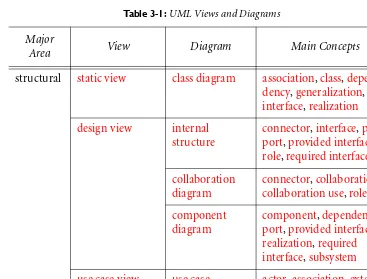
UML Views . . . .25
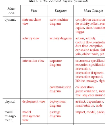
Static View . . . .28
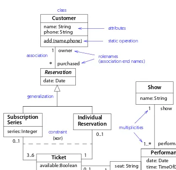
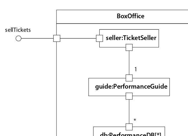
Design Views . . . .29
Use Case View . . . .34
State Machine View. . . .35
Activity View . . . .37
Interaction View . . . .37
Deployment View . . . .40
Model Management View . . . .42
x Contents
Chapter 4: Static View
. . .47
Overview . . . 47
Classifier . . . 48
Relationships . . . 52
Association. . . 53
Generalization. . . 57
Realization . . . 61
Dependency . . . 62
Constraint . . . 65
Instance . . . 66
Chapter 5: Design View
. . .69
Overview . . . 69
Structured Classifier . . . . 70
Collaboration . . . 71
Patterns . . . 73
Component . . . 73
Chapter 6: Use Case View
. . .77
Overview . . . 77
Actor . . . 77
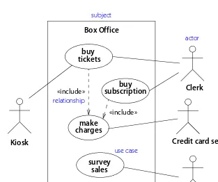
Use Case . . . 78
Chapter 7: State Machine View
. . .81
Overview . . . 81
State Machine . . . 81
Event . . . 82
State . . . 84
Transition . . . 85
Composite State. . . 89
Chapter 8: Activity View
. . .95
Overview . . . 95
Activity . . . 96
Activities and Other Views . . . 98
Action . . . 98
Chapter 9: Interaction View
. . .101
Overview . . . 101
Interaction . . . 101
Sequence Diagram . . . 102
Contents xi
Chapter 10: Deployment View
. . .109
Overview . . . .109
Node. . . .109
Artifact . . . .109
Chapter 11: Model Management View
. . .111
Overview . . . .111
Package . . . .111
Dependencies on Packages. . . .112
Visibility. . . .113
Import . . . .113
Model . . . .114
Chapter 12: Profiles
. . .115
Overview . . . .115
Stereotype. . . .116
Tagged Value . . . .117
Profile . . . .118
Chapter 13: UML Environment
. . .121
Overview . . . .121
Semantics Responsibilities . . . .121
Notation Responsibilities. . . .122
Programming Language Responsibilities . . . .123
Modeling with Tools . . . .124
Part 3: Reference
Chapter 14: Dictionary of Terms
. . .129
Part 4: Appendices
Appendix A: UML Metamodel
. . .685
Appendix B: Notation Summary
. . .689
Bibliography
. . .703
xiii
M
L
U
Preface
Goals
This book is intended to be a complete, useful reference to the Unified Modeling Language (UML) for the developer, architect, project manager, system engineer, programmer, analyst, contracting officer, customer, and anyone else who needs to specify, design, build, or understand complex software systems. It provides a full reference to the concepts and constructs of UML, including their semantics, nota-tion, and purpose. It is organized to be a convenient but thorough reference for the working professional developer. It also attempts to provide additional detail about issues that may not be clear from the standards documents and to provide a ratio-nale for many decisions that went into the UML.
This book is not intended as a guide to the UML standards documents or to the internal structure of the metamodel contained in them. The details of the meta-model are of interest to methodologists and UML tool builders, but most other developers have little need for the arcane details of the Object Management Group (OMG) documents. This book provides all the details of UML that most develop-ers need; in many cases, it makes information explicit that must otherwise be sought between the lines of the original documents. For those who wish to consult the source documents, they are on the OMG web site (www.omg.org).
This book is intended as a reference for those who already have some under-standing of object-oriented technology. For beginners, the original books by us and by other authors are listed in the bibliography; although some of the notation has changed, books such as [Rumbaugh-91], [Jacobson-92], [Booch-94], and
[Meyer-88] provide an introduction to object-oriented concepts that is still valid and therefore unnecessary to duplicate here. [Blaha-05] updates [Rumbaugh-91]
xiv Preface
UML does not require a particular development process. Although UML may be used with a variety of development processes, it was designed to support an iterative, incremental, use-case–driven process with a strong architectural focus— the kind we feel is most suitable for the development of modern, complex systems. To place UML in its context as a tool for software development, this book defines the stages of such a process, but they are not part of the UML standard. The Unified Software Development Process [Jacobson-99] describes in detail the kind of process we believe complements the UML and best supports software development.
Second Edition and UML Version
This second edition has been extensively modified from the first edition, which was published in 1999. This edition is based on the OMG “adopted” specification of UML version 2.0, with anticipated changes to the “available” specification being prepared by an OMG Finalization Task Force. Corrections to the book due to changes in the OMG UML specification will be posted on the publisher’s web site for this book at www.awprofessional.com/titles/0321245628. The information in
the book is accurate as of June 2004.
Original specification documents and up-to-date information about work on UML and related topics can be found on the OMG web site at www.omg.org.
Reference Manual and OMG Specification
UML is a large modeling language with many features. A reference manual that just repeats the original specification documents would not help readers much. As in any dictionary or encyclopedia, we have had to summarize information as clearly as possible while reducing the amount of material included. We have fre-quently chosen to emphasize common usages by omitting obscure special cases or redundant means of representing some concepts. This does not mean that those capabilities are useless, but most readers should be able to succeed without using them. The Reference Manual should not be regarded as the final authority on the UML language, however. As with any standard, the final authority rests with the official specifications, and these should be consulted to resolve disputes.
We have tried to follow these principles:
• Explain the main intent of a concept without getting lost in the details of the metamodel representation.
• Avoid discussion of abstract metaclasses. Modelers must ultimately use concrete metaclasses, which can be described more simply if the internal abstract layers are collapsed.
Preface xv
• Describe concepts from the complete specification. The OMG specification has a number of intermediate layers and compliance points that greatly complicate understanding of UML. We describe UML with all of its features. If your tool does not implement all of the facilities, then some of the features may be un-available to you, but it doesn’t usually hurt to know about them.
• Describe concepts from the viewpoint of their normal usage. Often the OMG specification goes to considerable trouble to express concepts in a general way. This is proper for a specification, but we feel that readers often understand con-cepts better if they are presented in a specific context and then generalized. If you are worried about the application of a concept in a complex, ambiguous sit-uation and you feel that the Reference Manual explanation may be inadequate, check the original specification. Unfortunately, however, even the OMG specifi-cation is sometimes ambiguous in complex situations.
Outline of the Book
The UML Reference Manual is organized into four parts: (1) an overview of UML history and of modeling, (2) a survey of UML concepts, (3) an alphabetical dictio-nary of UML terms and concepts, and (4) brief appendices.
The first part is an overview of UML—its history, purposes, and uses—to help you understand the origin of UML and the need it tries to fill.
The second part is a brief survey of UML concepts so that you can put all the features into perspective. The survey provides a brief overview of the views UML supports and shows how the various constructs work together. This part uses an example that walks through various UML views. It contains one chapter for each kind of UML view. This survey is not intended as a full tutorial or as a comprehen-sive description of concepts. It serves mainly to summarize and relate the various UML concepts, providing starting points for detailed readings in the dictionary.
The third part contains the reference material organized for easy access to each topic. The bulk of the book is an alphabetical dictionary of all of the concepts and constructs in UML. Each UML term of any importance has its own entry in the dictionary. The dictionary is meant to be complete; therefore, everything in the concept overview in Part 2 is repeated in more detail in the dictionary. The same or similar information has sometimes been repeated in multiple dictionary articles so that the reader can conveniently find it. Some common object-oriented terms that are not official UML concepts are included to provide context in examples and discussions.
xvi Preface
Dictionary Entry Formatting Conventions
The dictionary part of the book is organized as an alphabetical list of entries, each describing one concept in some detail. The articles represent a flat list of UML concepts at various conceptual levels. A high-level concept typically contains a summary of its subordinate concepts, each of which is fully described in a separate article. The articles are highly cross-referenced. The flat dictionary organization permits the description of each concept to be presented at a fairly uniform level of detail, without constant shifts in level for the nested descriptions that would be necessary for a sequential presentation. The hypertext format of the document should also make it convenient for reference. It should not be necessary to use the index much; instead, go directly to the main article in the dictionary for any term of interest and follow cross-references. This format is not necessarily ideal for learning the language; beginners are advised to read the overview description of UML found in Part 2 or to read introductory books on UML, such as the UML User Guide[Booch-99].
Dictionary articles have the following divisions, although not all divisions ap-pear in all articles.
Headword and brief definition
The name of the concept appears in boldface, set to the left of the body of the arti-cle. A brief definition follows in normal type. This definition is intended to cap-ture the main idea of the concept, but it may simplify the concept for concise presentation. Refer to the main article for precise semantics.
Predefined stereotypes are included as entries. A comment in parentheses fol-lowing the entry name identifies the modeling element to which they apply.
Semantics
Preface xvii
entry name
Dictionary entry format
A brief description of the concept in one or two sentences. See also related concept.
Semantics
A description of the semantics in several paragraphs.
Structure
A list of the subordinate concepts within the main concept.
item Description of an item. UML metamodel names are usually converted into plain English.
enumerated item An enumeration with several values. List of values:
value The meaning of this value of the item.
Another item. More complicated topics are described in separate paragraphs.
Example
An example may be included in semantics, notation, or stand alone.
Notation
Description of the notation, usually including a diagram or syntax.
Presentation options
Describes variant forms of notation, usually optional.
Style guidelines
States recommended practice although not mandatory.
Discussion
The author’s opinions or background explanations beyond UML.
History
Changes from UML version 1.x.
stereotype entry
(stereotype of Class)xviii Preface
organizational mechanisms have been used, their structure should be obvious to the reader. The names of properties are usually stated in plain language rather than using internal identifiers from the UML metamodel, but the correspondence is meant to be obvious.
Notation
This section contains a detailed description of the notation for the concept. Usu-ally, the notation section has a form that parallels the preceding semantics section, which it references, and it often has the same divisions. The notation section usu-ally includes one or more diagrams to illustrate the concept. The actual notation is printed in black. To help the reader understand the notation, many diagrams con-tain annotations in blue. Any material in blue is commentary and is not part of the actual notation.
Style guidelines
This optional section describes widespread style conventions. They are not man-datory, but they are followed within the UML specification itself. Recommended presentation guidelines may also be given in a separate section.
Example
This subsection contains examples of notation or illustrations of the use of the concept. Frequently, the examples also treat complicated or potentially confusing situations. If the examples are brief, they may be folded in with another section.
Discussion
This section describes subtle issues, clarifies tricky and frequently confused points, and contains other details that would otherwise digress from the more descriptive semantics section. A minority of articles have a discussion section.
This section also explains certain design decisions that were made in the devel-opment of the UML, particularly those that may appear counterintuitive or that have provoked strong controversy. Simple differences in taste are generally not covered.
Sometimes we express an opinion on the value (or lack thereof) of certain con-cepts. We recognize that others may disagree with these assessments. We have tried to confine opinions to the discussion section.
History
Preface xix
Syntax Conventions
Syntax expressions. Syntax expressions are given in a modified BNF format in a sans serif font (Myriad). Literal values that appear in the target sentence are printed in black, and the names of syntax variables and special syntax operators are printed in blue.
Text printed in black appears literally in the target string.
Punctuation marks (always printed in black) appear literally in the target string. Any word printed in blue ink represents a variable that must be replaced by an-other string or anan-other syntax production in the target string. Words may contain letters and hyphens. If a blue word is italicized or underlined, the actual replace-ment string must be italicized or underlined.
In code examples, comments are printed in blue to the right of the code text. Subscripts and L-brackets are used as syntax operators as follows:
expressionopt The expression is optional.
expressionlist, A comma-separated list of the expression may appear. If there is zero or one repetition, there is no separator. If a different punctuation mark than a comma appears in the subscript, then it is the separator.
⎣= expression⎦opt A pair of right angles ties together two or more terms that are considered a unit for optional or repeated occur-rences. In this example, the equal sign and the expression form one unit that may be omitted or included.
Two-level nesting is avoided. Particularly convoluted syntax may be simplified somewhat for presentation, but use of such convoluted syntax is likely to be con-fusing for humans anyway and should be avoided.
Literal strings. In running text, language keywords, names of model elements, and sample strings from models are shown in a sans serif font (Myriad).
Diagrams. In diagrams, blue text and arrows are annotations, that is, explanations of the diagram notation that do not appear in an actual diagram. Any text and symbols in black are actual diagram notation.
CD
xx Preface
Creators of UML
We wish to thank the many collaborators who built the UML specification through years of meetings, heated discussions, writing, and implementation of ideas. The list of contributors has grown significantly since UML1, and the OMG specification no longer lists the major contributors, who number between twenty and fifty depending on the threshold for inclusion, and even more if work influ-encing UML is included. It no longer appears possible to compile a complete list without overlooking many persons.
Most of all, we want to celebrate the hundreds of persons who contributed to the community of ideas from which UML was drawn—ideas in object-oriented technology, software methodology, programming languages, user interfaces, visual programming, and numerous other areas of computer science. It is impossible to list them all, or indeed to track even the major chains of influence, without a major scholarly effort, and this is an engineering book, not a historical review. Many of them are well known, but many good ideas also came from those who did not have the good fortune to become widely recognized. The bibliography includes a few of the lesser-known books that influenced the authors.
Acknowledgments
We would like to acknowledge the reviewers who made this book possible. For the second edition, they include Conrad Bock, Martin Gogolla, Øystein Haugen, Bir-ger Møller-Pedersen, and Ed Seidewitz. For the first edition, we received feedback from Mike Blaha, Conrad Bock, Perry Cole, Bruce Douglass, Martin Fowler, Eran Gery, Pete McBreen, Gunnar Övergaard, Karin Palmkvist, Guus Ramackers, Tom Schultz, Ed Seidewitz, and Bran Selic.
On a more personal note, I wish to thank Professor Jack Dennis, who inspired my work in modeling and the work of many other students more than thirty years ago. The ideas from his Computations Structures Group at MIT have borne much fruit, and they are not the least of the sources of UML. I must also thank Mary Loomis and Ashwin Shah, with whom I developed the original ideas of OMT, and my former colleagues at GE R&D Center, Mike Blaha, Bill Premerlani, Fred Eddy, and Bill Lorensen, with whom I wrote the OMT book.
Finally, without the patience of my wife, Madeline, and my sons, Nick and Alex, there would have been no UML and no book about it.
M
L
U
Part 1: Background
3
M
L
U
1
UML Overview
This chapter is a quick overview of UML and what it is good for.
Brief Summary of UML
The Unified Modeling Language (UML) is a general-purpose visual modeling lan-guage that is used to specify, visualize, construct, and document the artifacts of a software system. It captures decisions and understanding about systems that must be constructed. It is used to understand, design, browse, configure, maintain, and control information about such systems. It is intended for use with all develop-ment methods, lifecycle stages, application domains, and media. The modeling language is intended to unify past experience about modeling techniques and to incorporate current software best practices into a standard approach. UML in-cludes semantic concepts, notation, and guidelines. It has static, dynamic, envi-ronmental, and organizational parts. It is intended to be supported by interactive visual modeling tools that have code generators and report writers. The UML specification does not define a standard process but is intended to be useful with an iterative development process. It is intended to support most existing object-oriented development processes.
The UML captures information about the static structure and dynamic behav-ior of a system. A system is modeled as a collection of discrete objects that interact to perform work that ultimately benefits an outside user. The static structure de-fines the kinds of objects important to a system and to its implementation, as well as the relationships among the objects. The dynamic behavior defines the history of objects over time and the communications among objects to accomplish goals. Modeling a system from several separate but related viewpoints permits it to be understood for different purposes.
4 Part 1 • Background
manage the versioning of model units in a complex development environment. It contains constructs for representing implementation decisions and for organizing run-time elements into components.
UML is not primarily a programming language. It can be used to write pro-grams, but it lacks the syntactic and semantic conveniences that most program-ming languages provide to ease the task of programprogram-ming. Tools can provide code generators from UML into a variety of programming languages, as well as con-struct reverse-engineered models from existing programs. The UML is not a highly formal language intended for theorem proving. There are a number of such languages, but they are not easy to understand or to use for most purposes. The UML is a general-purpose modeling language. For specialized domains, such as GUI layout, VLSI circuit design, or rule-based artificial intelligence, a more spe-cialized tool with a special language might be appropriate. UML is a discrete mod-eling language. It is not intended to model continuous systems such as those found in engineering and physics. UML is intended to be a universal general-purpose modeling language for discrete systems such as those made of software, firmware, or digital logic.
UML History
UML was developed in an effort to simplify and consolidate the large number of object-oriented development methods that had emerged.
Object-oriented development methods
Chapter 1 • UML Overview 5
simpler, whether or not this was actually true, and there was less need for review by outside organizations.
The first object-oriented language is generally acknowledged to be Simula-67
[Birtwistle-75], developed in Norway in 1967. This language never had a signifi-cant following, although it greatly influenced the developers of several of the later object-oriented languages. The work of Dahl and Nygaard had a profound influ-ence on the development of object orientation. The object-oriented movement be-came active with the widespread availability of Smalltalk in the early 1980s, followed by other object-oriented languages, such as Objective C, C++, Eiffel, and CLOS. The actual usage of object-oriented languages was limited at first, but object-orientation attracted a lot of attention. About five years after Smalltalk be-came widely known, the first object-oriented development methods were pub-lished by Shlaer/Mellor [Shlaer-88] and Coad/Yourdon [Coad-91], followed soon thereafter by Booch [Booch-94], Rumbaugh/Blaha/Premerlani/Eddy/Lorensen
[Rumbaugh-91] (updated as [Blaha-05]), and Wirfs-Brock/Wilkerson/Wiener
[Wirfs-Brock-90] (note that copyright years often begin in July of the previous cal-endar year). These books, added to earlier programming-language design books by Goldberg/Robson [Goldberg-83], Cox [Cox-86], and Meyer [Meyer-88], started the field of object-oriented methodology. The first phase was complete by the end of 1990. The Objectory book [Jacobson-92] was published slightly later, based on work that had appeared in earlier papers. This book took a somewhat different approach, with its focus on use cases and the development process.
Over the next five years, a plethora of books on object-oriented methodology appeared, each with its own set of concepts, definitions, notation, terminology, and process. Some added useful new concepts, but overall there was a great simi-larity among the concepts proposed by different authors. Many of the newer books started from one or more of the existing methods and made extensions or minor changes. The original authors were not idle either; most of them updated their original work, often incorporating good ideas from other authors. In general, there emerged a pool of common core concepts, together with a wide variety of concepts embraced by one or two authors but not widely used. Even in the core concepts, there were minor discrepancies among methods that made detailed comparison somewhat treacherous, especially for the casual reader.
Unification effort
There were some early attempts to unify concepts among methods. A notable example was Fusion by Coleman and his colleagues [Coleman-94], which in-cluded concepts from OMT [Rumbaugh-91], Booch [Booch-94], and CRC
6 Part 1 • Background
Rumbaugh joined Booch at Rational Software Corporation in 1994. They began combining the concepts from the OMT and Booch methods, resulting in a first proposal in 1995. At that time, Jacobson also joined Rational and began working with Booch and Rumbaugh. Their joint work was called the Unified Modeling Language (UML). The momentum gained by having the authors of three of the top methods working together to unify their approaches shifted the balance in the object-oriented methodology field, where there had previously been little incen-tive (or at least little willingness) for methodologists to abandon some of their own concepts to achieve harmony.
In 1996, the Object Management Group (OMG) issued a request for proposals for a standard approach to object-oriented modeling. UML authors Booch, Jacob-son, and Rumbaugh began working with methodologists and developers from other companies to produce a proposal attractive to the membership of OMG, as well as a modeling language that would be widely accepted by tool makers, meth-odologists, and developers who would be the eventual users. Several competing ef-forts also were started. Eventually, all the proposals coalesced in the final UML proposal that was submitted to the OMG in September 1997. The final product is a collaboration among many people. We began the UML effort and contributed a few good ideas, but the ideas in it are the product of many minds.
Standardization
The Unified Modeling Language was adopted unanimously by the membership of the OMG as a standard in November 1997 [UML-98]. The OMG assumed respon-sibility for the further development of the UML standard. Even before final adop-tion, a number of books were published outlining the highlights of the UML. Many tool vendors announced support or planned support for the UML, and sev-eral methodologists announced that they would use UML notation for further work. UML has now supplanted most, if not all, of the previous modeling nota-tions in development processes, modeling tools, and articles in the technical litera-ture. The emergence of the UML appears to have been attractive to the general computing public because it consolidates the experiences of many authors with an official status that has reduced gratuitous divergence among tools.
Noteworthy is a series of international research conferences with the title UML yyyy, where yyyy is a year starting with 1998 and continuing annually [UMLConf]. Also note the yearly [ECOOP] and [OOPSLA] conferences dealing with object-oriented technology in general.
UML2
Chapter 1 • UML Overview 7
it with additional capabilities that were desired in several application domains. Proposals were developed from November 2000 to July 2003, with a specification of UML version 2.0 being adopted by the OMG membership shortly thereafter
[UML-04]. The adopted specification underwent the normal OMG finalization process to fix bugs and problems encountered in initial implementation, with a fi-nal available specification expected at the end of 2004 or beginning of 2005.
In this book, we use the term UML1 to refer to UML specification versions 1.1 to 1.5 and UML2 to refer to UML specification versions 2.0 and higher.
New features. In general, UML2 is mostly the same as UML1, especially regarding the most commonly used, central features. Some problem areas have been modi-fied, a few major enhancements have been added, and many small bugs have been fixed, but users of UML1 should have little trouble using UML2. The new version may be considered like a new version of a programming language or an applica-tion. Some of the most important changes visible to users are:
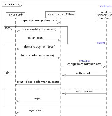
• Sequence diagram constructs and notation based largely on the ITU Message Sequence Chart standard, adapted to make it more object-oriented.
• Decoupling of activity modeling concepts from state machines and the use of notation popular in the business modeling community.
• Unification of activity modeling with the action modeling added in UML ver-sion 1.5, to provide a more complete procedural model.
• Contextual modeling constructs for the internal composition of classes and col-laborations. These constructs permit both loose and strict encapsulation and the wiring of internal structures from smaller parts.
• Repositioning of components as design constructs and artifacts as physical enti-ties that are deployed.
Internal mechanisms. Other changes affect the internal representation of UML constructs (the metamodel) and its relationship to other specifications. These changes will not concern most users directly, but they are important to toolmakers because they affect interoperability across multiple specifications, therefore they will affect users indirectly:
• Unification of the core of UML with the conceptual modeling parts of MOF (Meta-Object Facility). This permits UML models to be handled by generic MOF tools and repositories.
• Restructuring of the UML metamodel to eliminate redundant constructs and to permit reuse of well-defined subsets by other specifications.
8 Part 1 • Background
Other sources
In addition to the various development methods cited above and a number of oth-ers that came a bit later, certain UML views show strong influences from particular non-object-oriented sources.
The static view, with classes connected by various relationships, is strongly in-fluenced by Peter Chen’s Entity-Relationship (ER) model originally developed in 1976. The influence came into UML through most of the early object-oriented methods. The ER model also heavily influenced database systems. The program-ming language world and the database world have unfortunately mostly gone their separate ways.
State machine models have been used in computer science and electrical engi-neering for many years. David Harel’s statecharts are an important extension to classical state machines that add the concept of nested and orthogonal states. Harel’s ideas were adapted by OMT, and from there into other methods and even-tually into UML, where they form the basis of the state machine view.
The sequence diagram notation of UML2 is taken from the ITU Message Se-quence Chart (MSC) standard [ITU-T Z.120], adapted to make it match other UML concepts better. This standard, which has been widely used in the telecom-munications industry, replaces the sequence diagram notation of UML1 by adding a number of structured constructs to overcome problems in the previous UML1 notation. The ITU is considering whether to adopt some or all of the changes into the ITU standard.
The structured classifier concepts of UML2 were strongly influenced by the real-time engineering constructs of SDL [ITU-T Z.100], MSC, and the ROOM method
[Selic-94].
The activity diagram notation of UML1, and even more that of UML2, is heavily influenced by various business process modeling notations. Because no single business process modeling notation was dominant, the UML notation was selected from various sources.
Chapter 1 • UML Overview 9
What does
unified
mean?
The word unified has the following relevant meanings for UML.
Across historical methods and notations. The UML combines the commonly ac-cepted concepts from many object-oriented methods, selecting a clear definition for each concept, as well as a notation and terminology. The UML can represent most existing models as well as or better than the original methods can.
Across the development lifecycle. The UML is seamless from requirements to de-ployment. The same set of concepts and notation can be used in different stages of development and even mixed within a single model. It is unnecessary to translate from one stage to another. This seamlessness is critical for iterative, incremental development.
Across application domains. The UML is intended to model most application do-mains, including those involving systems that are large, complex, real-time, dis-tributed, data or computation intensive, among other properties. There may be specialized areas in which a special-purpose language is more useful, but UML is intended to be as good as or better than any other general-purpose modeling lan-guage for most application areas.
Across implementation languages and platforms. The UML is intended to be usable for systems implemented in various implementation languages and plat-forms, including programming languages, databases, 4GLs, organization docu-ments, firmware, and so on. The front-end work should be identical or similar in all cases, while the back-end work will differ somewhat for each medium.
Across development processes. The UML is a modeling language, not a description of a detailed development process. It is intended to be usable as the modeling lan-guage underlying most existing or new development processes, just as a general-purpose programming language can be used in many styles of programming. It is particularly intended to support the iterative, incremental style of development that we recommend.
10 Part 1 • Background
Goals of UML
There were a number of goals behind the development of UML. First and most important, UML is a general-purpose modeling language that all modelers can use. It is nonproprietary and based on common agreement by much of the com-puting community. It is meant to include the concepts of the leading methods so that it can be used as their modeling language. At the very least, it was intended to supersede the models of OMT, Booch, and Objectory, as well as those of other par-ticipants of the proposal. It was intended to be as familiar as possible; whenever possible, we used notation from OMT, Booch, Objectory, and other leading meth-ods. It is meant to support good practices for design, such as encapsulation, sepa-ration of concerns, and capture of the intent of a model construct. It is intended to address current software development issues, such as large scale, distribution, con-currency, patterns, and team development.
UML is not intended to be a complete development method. It does not include a step-by-step development process. We believe that a good development process is crucial to the success of a software development effort, and we propose one in a companion book [Jacobson-99]. It is important to realize that UML and a process for using UML are two separate things. UML is intended to support all, or at least most, of the existing development processes. UML includes the concepts that we believe are necessary to support a modern iterative process based on building a strong architecture to solve user-case–driven requirements.
A final goal of UML was to be as simple as possible while still being capable of modeling the full range of practical systems that need to be built. UML needs to be expressive enough to handle all the concepts that arise in a modern system, such as concurrency and distribution, as well as software engineering mechanisms, such as encapsulation and components. It must be a universal language, like any general-purpose programming language. Unfortunately, that means that it cannot be small if we want it to handle things other than toy systems. Modern languages and mod-ern operating systems are more complicated than those of 50 years ago because we expect much more of them. UML has several kinds of models; it is not something you can master in one day. It is more complicated than some of its antecedents be-cause it is intended to be more comprehensive. But you don’t have to learn it all at once, any more than you would a programming language, an operating system, or a complex user application, not to mention a natural language or skill.
Complexity of UML
Chapter 1 • UML Overview 11
programming languages, multimedia editing applications, spreadsheet editors, and desktop publishing systems. Such applications can be kept small only at the cost of making them toys, and the developers of UML did not wish it to be a toy.
The complexity of UML must be understood in light of its history:
• UML is a product of consensus of persons with varied goals and interests. It shares the qualities of the product of a democratic process. It is not as clean or coherent as the product of a single will. It contains superfluous features (but dif-ferent persons might disagree about exactly what is superfluous). It contains overlapping features that are not always well integrated. Most of all, it lacks a consistent viewpoint. Unlike a programming language, which has a fairly nar-row usage, it is intended for all kinds of things, from business modeling to graphical programming. Wide breadth of applicability usually comes at the ex-pense of specificity.
• It was originally the merger of four or five leading modeling approaches, and later has been the target for accommodating a number of existing notations, such as SDL (Specification and Description Language, [ITU-T Z.100]), various business modeling languages (which themselves had no single standard), action languages, state machine notations, and so on. The desire to preserve previous notation often creates inconsistencies across features and includes redundant notation intended to cater to the familiarities of certain usage groups.
• The official specification documents have been written by teams of uneven abil-ity. There is a wide variation in style, completeness, precision, and consistency among various sections of the documents.
• UML is not a precise specification in the manner of a formal language. Al-though the computer science community holds formality to be a virtue, few mainstream programming languages are precisely defined, and formal lan-guages are often inaccessible even to experts. It should also be noted that model-ing is not the same as codmodel-ing. In the construction industry, blueprints are written in an informal style using many conventions that depend on the com-mon sense of the craftsperson, but buildings are built from them successfully. • The semantics sections sometimes contain vague statements without adequate
explanation and examples. Terms are introduced in metamodels and not well distinguished from other terms. There are too many fine distinctions that some-one thought important but did not explain clearly.
• There is far too much use of generalization at the expense of essential distinc-tions. The myth that inheritance is always good has been a curse of object-orientation from its earliest days.
12 Part 1 • Background
UML Assessment
• UML is messy, imprecise, complex, and sprawling. That is both a fault and a vir-tue. Anything intended for such widespread usage is going to be messy.
• You don’t have to know or use every feature of UML any more than you need to know or use every feature of a large software application or programming lan-guage. There is a small set of central concepts that are widely used. Other fea-tures can be learned gradually and used when needed.
• UML can be and has been used in many different ways in real-world develop-ment projects.
• UML is more than a visual notation. UML models can be used to generate code and test cases. This requires an appropriate UML profile, use of tools matched to the target platform, and choices among various implementation trade-offs. • It is unnecessary to listen too much to UML language lawyers. There is no single
right way to use it. It is one of many tools that a good developer uses. It doesn’t have to be used for everything. You can modify it to suit your own needs pro-vided you have the cooperation of your colleagues and software tools.
UML Concept Areas
UML concepts and models can be grouped into the following concept areas.
Static structure. Any precise model must first define the universe of discourse, that is, the key concepts from the application, their internal properties, and their rela-tionships to each other. This group of constructs is the static view. Application concepts are modeled as classes, each of which describes discrete objects that hold information and communicate to implement behavior. The information they hold is modeled as attributes; the behavior they perform is modeled as operations. Sev-eral classes can share their common structure using generalization. A child class adds incremental structure and behavior to the structure and behavior that it ob-tains by inheritance from the common parent class. Objects also have run-time connections to other individual objects. Such object-to-object relationships are modeled as associations among classes. Some relationships among elements are grouped together as dependency relationships, including relationships among lev-els of abstraction, binding of template parameters, granting of permission, and us-age of one element by another. Classes may have interfaces, which describe their externally-visible behavior. Other relationships are include and extend dependen-cies of use cases. The static view is notated using class diagrams and its variants. The static view can be used to generate most data structure declarations in a pro-gram. There are several other kinds of elements in UML diagrams, such as
Chapter 1 • UML Overview 13
and they behave much like classes with certain additions and restrictions on each kind of classifier.
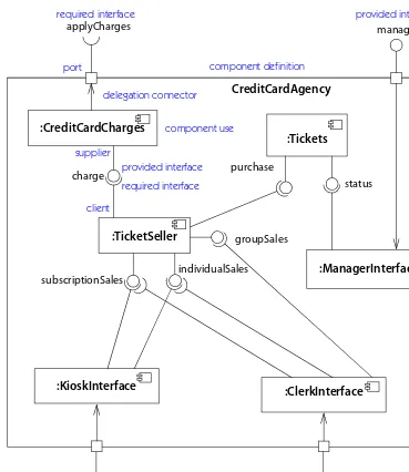
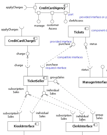
Design constructs. UML models are meant for both logical analysis and designs in-tended for implementation. Certain constructs represent design items. A struc-tured classifier expands a class into its implementation as a collection of parts held together by connectors. A class can encapsulate its internal structure behind exter-nally visible ports. A collaboration models a collection of objects that play roles within a transient context. A component is a replaceable part of a system that con-forms to and provides the realization of a set of interfaces. It is intended to be eas-ily substitutable for other components that meet the same specification.
Deployment constructs. A node is a run-time computing resource that defines a lo-cation. An artifact is a physical unit of information or behavior description in a computing system. Artifacts are deployed on nodes. An artifact can be a manifes-tation, that is, an implementation, of a component. The deployment view de-scribes the configuration of nodes in a running system and the arrangement of artifacts on them, including manifestation relationships to components.
Dynamic behavior. There are three ways to model behavior. One is the life history of one object as it interacts with the rest of the world; another is the communica-tion patterns of a set of connected objects as they interact to implement behavior; the third is the evolution of the execution process as it passes through various activities.
The view of an object in isolation is a state machine—a view of an object as it re-sponds to events based on its current state, performs actions as part of its response, and transitions to a new state. State machines are displayed in state machine dia-grams.
An interaction overlays a structured classifier or collaboration with the flow of
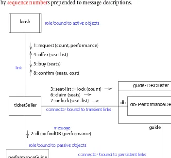
messages between parts. Interactions are shown in sequence diagrams and com-munication diagrams. Sequence diagrams emphasize time sequences, whereas communication diagrams emphasize object relationships.
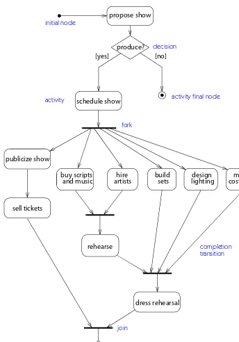
An activity represents the execution of a computation. It is modeled as a set of
activity nodes connected by control flows and data flows. Activities can model both sequential and concurrent behavior. They include traditional flow-of-control constructs, such as decisions and loops. Activity diagrams may be used to show computations as well as workflows in human organizations.
14 Part 1 • Background
Model organization. Computers can deal with large flat models, but humans can-not. In a large system, the modeling information must be divided into coherent pieces so that teams can work on different parts concurrently. Even on a smaller system, human understanding requires the organization of model content into
packages of modest size. Packages are general-purpose hierarchical organizational units of UML models. They can be used for storage, access control, configuration management, and constructing libraries that contain reusable model fragments. A
dependency between packages summarizes the dependencies among the package contents. A dependency among packages can be imposed by the overall system ar-chitecture. Then the contents of the packages must conform to the package depen-dencies and to the imposed system architecture.
Profiles. No matter how complete the facilities in a language, people will want to make extensions. UML contains a limited extensibility capability that should ac-commodate most of the day-to-day needs for extensions, without requiring a change to the basic language. A stereotype is a new kind of model element with the same structure as an existing element, but with additional constraints, a different interpretation and icon, and different treatment by code generators and other back-end tools. A stereotype defines a set of tagged values. A tagged value is a user-defined attribute that applies to model elements themselves, rather than objects in the run-time system. For example, tagged values may indicate project manage-ment information, code generator guidance, and domain-specific information. A
15
M
L
U
2
The Nature and Purpose of Models
This chapter explains what models are, what they are good for, and how they are used. It also explains the various grades of models: ideal, partial, and tool-based.
What Is a Model?
A model is a representation in a certain medium of something in the same or an-other medium. The model captures the important aspects of the thing being mod-eled from a certain point of view and simplifies or omits the rest. Engineering, architecture, and many other creative fields use models.
A model is expressed in a medium that is convenient for working. Models of buildings may be drawings on paper, - figures made of cardboard and papier-mâché, or finite-element equations in a computer. A construction model of a building shows the appearance of the building but can also be used to make engi-neering and cost calculations.
A model of a software system is made in a modeling language, such as UML. The model has both semantics and notation and can take various forms that in-clude both pictures and text. The model is intended to be easier to use for certain purposes than the final system.
What Are Models For?
Models are used for several purposes.
16 Part 1 • Background
Different models of a software system may capture requirements about its appli-cation domain, the ways users will use it, its breakdown into modules, common patterns used in its construction, and other things. Stakeholders include the archi-tect, analysts, programmers, project manager, customers, funders, end users, and operators. Various kinds of UML models are used.
To think about the design of a system. An architect uses models on paper, on a computer, or as - constructs to visualize and experiment with possible designs. The simplicity of creating and modifying small models permits creative thought and innovation at little cost.
A model of a software system helps developers explore several architectures and design solutions easily before writing code. A good modeling language allows the designer to get the overall architecture right before detailed design begins.
To capture design decisions in a mutable form separate from the requirements. One model of a building shows the external appearance agreed to with the customer. Another model shows the internal routing of wires, pipes, and ventilation ducts. There are many ways to implement these services. The final model shows a design that the architect believes is a good one. The customer may verify this information, but often customers are not concerned about the details, as long as they work.
One model of a software system can capture the external behavior of a system and the real-world domain information represented by the system. Another model shows the internal classes and operations that implement the external behavior. There are many ways to implement the behavior; the final design model shows one approach that the designer believes is a good one.
To generate usable work products. A model of a building can be used to generate various kinds of products. These include a bill of materials, a simulated animated walkthrough, a table of deflections at various wind speeds, and a visualization of strain at various points in the frame.
A model of a software system can be used to generate class declarations, proce-dure bodies, user interfaces, databases, scenarios of legal use, configuration scripts, and lists of race conditions.
To organize, find, filter, retrieve, examine, and edit information about large sys-tems. A model of a building organizes information by service: structural, electrical, plumbing, ventilation, decoration, and so on. Unless the model is on a computer, however, finding things and modifying them are not so easy. If it is on a computer, changes can be made and recalled easily, and multiple designs can be easily ex-plored while sharing some common elements.
Chapter 2 • The Nature and Purpose of Models 17
Keeping a model of any size accurate is impossible without having an editing tool that manages the model. An interactive graphical model editor can present infor-mation in different formats, hide inforinfor-mation that is unnecessary for a given pur-pose and show it again later, group related operations together, make changes to individual elements, as well as change groups of elements with one command, and so on.
To explore multiple solutions economically. The advantages and risks of different design methods for buildings may not be clear at first. For example, different sub-structures may interact in complicated ways that cannot be evaluated in an engi-neer’s head. Models can explore the various designs and permit calculations of costs and risks before the actual building is constructed.
Models of a large software system permit several designs to be proposed and compared. The models are not constructed in full detail, of course, but even a rough model can expose many issues the final design must deal with. Modeling permits several designs to be considered, at a small cost of implementing any one design.
To master complex systems. An engineering model of a tornado approaching a building provides understanding that is not possible from a real-world building. A real tornado cannot be produced on demand, and it would destroy the measuring instruments, anyway. Many fast, small, or violent physical processes can now be understood using physical models.
A model of a large software system permits dealing with complexity that is too difficult to deal with directly. A model can abstract to a level that is comprehensi-ble to humans, without getting lost in details. A computer can perform compli-cated analyses on a model in an effort to find possible trouble spots, such as timing errors and resource overruns. A model can determine the potential impact of a change before it is made, by exploring dependencies in the system. A model can also show how to restructure a system to reduce such effects.
Levels of Models
Models take on different forms for various purposes and appear at different levels of abstraction. The amount of detail in the model must be adapted to one of the following purposes.
18 Part 1 • Background
process. Its purpose is to produce ideas. The final “thinking models” should be preserved even after the focus shifts to design issues, however. Early models do not require the detail or precision of an implementation model, and they do not re-quire a full range of implementation concepts. Such models use a subset of UML constructs, a more limited subset than later design models.
When an early model is a complete view of a system at a given precision—for example, an analysis model of what must be done—then it should be preserved when development shifts to the next stage. There is an important difference be-tween adding detail (in which case, the chain of reasoning should be preserved) and the normal random-walk process of exploring many dead ends before arriving at the right solution. In the latter case, it is usually overwhelming and unnecessary to save the entire history except in extraordinary situations in which complete traceability is required.
Abstract specifications of the essential structure of a system. Models in the analysis or preliminary design stages focus on the key concepts and mechanisms of the eventual system. They correspond in certain ways with the final system. But details are missing from the model, which must be added explicitly during the design pro-cess. The purpose of the abstract models is to get the high-level pervasive issues correct before tackling the more localized details. These models are intended to be evolved into the final models by a careful process that guarantees that the final sys-tem correctly implements the intent of the earlier models. There must be traceabil-ity from these essential models to the full models; otherwise, there is no assurance that the final system correctly incorporates the key properties that the essential model sought to show. Essential models focus on semantic intent. They do not need the full range of implementation options. Indeed, low-level performance dis-tinctions often obscure the logical semantics. The path from an essential model to a complete implementation model must be clear and straightforward, however, whether it is generated automatically by a code generator or evolved manually by a designer.
Full specifications of a final system. An implementation model includes enough information to build the system. It must include not only the logical semantics of the system and the algorithms, data structures, and mechanisms that ensure proper performance, but also organizational decisions about the system artifacts that are necessary for cooperative work by humans and processing by tools. This kind of model must include constructs for packaging the model for human under-standing and for computer convenience. These are not properties of the target ap-plication itself. Rather, they are properties of the construction process.
Chapter 2 • The Nature and Purpose of Models 19
Ultimately, we need models that specify the general case; that is what a program is, after all. Examples of typical data structures, interaction sequences, or object his-tories can help a human trying to understand a complicated situation, however. Examples must be used with some care. It is logically impossible to induce the gen-eral case from a set of examples, but well-chosen prototypes are the way most peo-ple think. An exampeo-ple model includes instances rather than general descriptors. It therefore tends to have a different feel than a generic descriptive model. Example models usually use only a subset of the UML constructs, those that deal with in-stances. Both descriptive models and exemplar models are useful in modeling a system.
Complete or partial descriptions of systems. A model can be a complete description of a single system with no outside references. More often, it is organized as a set of distinct, discrete units, each of which may be stored and manipulated separately as a part of the entire description. Such models have “loose ends” that must be bound to other models in a complete system. Because the pieces have coherence and meaning, they can be combined with other pieces in various ways to produce many different systems. Achieving reuse is an important goal of good modeling.
Models evolve over time. Models with greater degrees of detail are derived from more abstract models, and more concrete models are derived from more logical models. For example, a model might start as a high-level view of the entire system, with a few key services in brief detail and no embellishments. Over time, much more detail is added and variations are introduced. Also over time, the focus shifts from a front-end, user-centered logical view to a back-end, implementation-centered physical view. As the developers work with a system and understand it better, the model must be iterated at all levels to capture that understanding; it is impossible to understand a large system in a single, linear pass. There is no one “right” form for a model.
What Is in a Model?
Semantics and presentation. Models have two major aspects: semantic informa-tion (semantics) and visual presentainforma-tion (notainforma-tion).
20 Part 1 • Background
The visual presentation shows semantic information in a form that can be seen, browsed, and edited by humans. Presentation elements carry the visual presenta-tion of the model—that is, they show it in a form directly apprehensible by hu-mans. They do not add meaning, but they do organize the presentation to emphasize the arrangement of the model in a usable way. They therefore guide hu-man understanding of a model. Presentation elements derive their sehu-mantics from semantic model elements. But inasmuch as the layout of the diagrams is supplied by humans, presentation elements are not completely derivable from logical ele-ments. The arrangement of presentation elements may convey connotations about semantic relationships that are too weak or ambiguous to formalize in the seman-tic model but are nevertheless suggestive to humans.
Context. Models are themselves artifacts in a computer system, and they are used within a larger context that gives them their full meaning. This context includes the internal organization of the model, annotations about the use of each model in the overall development process, a set of defaults and assumptions for element cre-ation and manipulcre-ation, and a relcre-ationship to the environment in which they are used.
Models require an internal organization that permits simultaneous use by mul-tiple work groups without undue interference. This decomposition is not needed for semantic reasons—a large monolithic model would be as precise as a set of models organized into coherent packages, maybe even more precise because the organizational boundaries complicate the job of defining precise semantics. But teams of workers could not work effectively on a large monolithic model without constantly getting in each other’s way. Moreover, a monolithic model has no pieces that can be reused in other situations. Finally, changes to a large model have conse-quences that are difficult to determine. Changes to a small, isolated piece of a large model can be tractable if the model is properly structured into subsystems with defined interfaces. In any case, dividing large systems into a hierarchy of well-chosen pieces is the most reliable way to design large systems that humans have in-vented over thousands of years.
Chapter 2 • The Nature and Purpose of Models 21
The commands used to create and modify a model are not part of the semantics of the modeling language any more than the commands of a text editor or browser are part of the semantics of a programming language. Model element properties do not have default values; in a particular model, they simply have values. For practical development, however, humans need to build and modify models with-out having to specify everything in full detail. Default values exist in the boundary between the modeling language and the editing tool that supports it. They are re-ally defaults on the tool commands that create a model, although they may tran-scend an individual tool and become user expectations about the implementation of the language by tools in general.
Models are not built and used in isolation. They are part of a larger environment that includes modeling tools, languages and compilers, operating systems, net-works of computers, implementation constraints, and so on. The information about a system includes information about all parts of the environment. Some of it will be stored in a model even though it is not semantic information. Examples in-clude project management annotations (discussed above), code generation hints and directives, model packaging, and default command settings for an editor tool. Other information may be stored separately. Examples include program source code and operating system configuration commands. Even if some information is part of a model, the responsibility for interpreting it may lie in various places, in-cluding the modeling language, the modeling tool, the code generator, the com-piler, a command language, and so on. This book describes the interpretation of models that is defined in the UML specification, and which therefore applies to all uses of UML. But when operating in a physical development environment, other sources may add additional interpretations beyond that given in the UML specifi-cation.
What Does a Model Mean?
A model is a generator of potential configurations of systems; the possible systems are its extent, or values. Ideally, all configurations consistent with the model should be possible. Sometimes, however, it is not possible to represent all constraints within a model. A model is also a description of the generic structure and meaning of a system. The descriptions are its intent, or meaning. A model is always an ab-straction at some level. It captures the essential aspects of a system and ignores some of the details. The following aspects must be considered for models.
22 Part 1 • Background
of detail. An early model or a high-level model may not require full detail, because additional detail may be irrelevant for the purpose at hand. Models at different levels of precision can be used across the life of a project. A model intended for code generation requires at least some programming language issues to be ad-dressed. Typically, models have low precision during early analysis. They gain de-tail as the development cycle progresses, so the final models have considerable detail and precision.
Specification versus implementation. A model can tell what something does ( spec-ification) as well as how the function is accomplished (implementation). These as-pects should be separated in modeling. It is important to get the what correct before investing much time in the how. Abstracting away from implementation is an important facet of modeling. There may be a chain of several specification-implementation relationships, in which each specification-implementation defines the specifi-cations for the next layer.
Description versus instance. Models are descriptions. The things they describe are instances, which usually appear in models only as examples. Most instances exist only as part of the run-time execution. Sometimes, however, run-time instances are themselves descriptions of other things. We call these hybrid objects metadata. Looked at more deeply, it is unrealistic to insist that everything is either an in-stance or a description. Something is an inin-stance or a description not in isolation but only in relation to something else, and most things can be approached from multiple viewpoints.