Autonomous
Underwater Biorobots
Tareq Assaf, Cesare Stefanini, and Paolo Dario
T
his article describes a new design for wireless power transfer in autonomousunderwater robots. The aim is to propose a solution for battery charging by taking into account the morphological and dimensional constraints of robots requiring small and low-weight internal modules. An innovative design is presented for inductive power transfer suitable for a wide range of applications. The system is conceptually equivalent to a transformer in which the core can be separated into two parts during operation, one for each coil. Inductive power transfer is selected to have a system to easily and reliably charge different kinds of underwater robots. The secondary coil and its magnetic core are designed to be placed inside a bioinspired robot; the weight, dimensions, and power output for battery charging are optimized. The shape of the secondary magnetic core section is hollow to house the control electronics and sensors. The primary coil is the power inductor, which is placed in a docking unit outside the robot. Experimental results are also reported.
Project LAMPETRA
The framework for the development of the device described in this article is the project Life-Like Artifacts for Motor-Postural Experiments and Development of New Control Technologies Inspired by Rapid Animal locomotion (LAMPETRA), a three-year (2008–2010) collaborative
A Wireless
System for
Power Transfer
PHOTO COURTESY OF TAREQ ASSAF,CESARE STEFANINI, AND PAOLO DARIO
Date of publication: 1 August 2013
research project funded under the Seventh EU framework program, theme ICT-2007.8.3-FET proactive 3, “Bio-ICT Convergence,” aimed at consolidating multidisciplinary Bio-ICT research carried out by a recently established scientific community. It involves four European countries: Italy, Swe-den, France, and Switzerland. The objective of the project LAMPETRA is to develop lamprey and salamander bioin-spired artifacts as tools for neuroscientific studies on goal-directed locomotion. The partners have already developed early prototypes: a lamprey-like artifact by Scuola Superiore Sant’Anna—Pisa (SSSA) [1], [2] and
a salamander-like artifact [3], [4] by the Biologically Inspired Robotics Group-Lausanne—Switzerland (EPFL). In the lamprey prototype (SSSA), both power supply and con-trol were wired. This article focuses on the adoption of on-board batteries to enhance free locomotion. It also addresses the on-board integration of control electronics and sensors. In this article, a wireless solution for battery charging is described, as a number of constraints are provided by the artifact. The robot is covered by a smooth thin waterproof skin layer, which is supposed to be deli-cately touched during a charging process carried out through a non-contact power transfer. In addition, issues such as body flexibility and space for internal electronics mean that there has to be a bulk miniatur-ization (axial and transversal) of the on-board power receiving module.
The device introduced in this article is a transformer-based system that can transfer electric energy from a burrow-like docking station to the robot, for feeding through battery charging.
State of the Art
Docking and Power Transfer System
Despite the wide range of theories, methodologies, and devices for wireless power transfer described in the literature, we focus on those solutions adopted in the field of oceanic exploration for autonomous underwater vehicles (AUVs). Shape, dimensions, and energy requests change case by case, and the working principles of the charging systems can be grouped into three classes: direct electric contact, electrome-chanic generators, and inductive transfer [5], [6].
In the first type, energy is usually transferred to electric contacts powering an on-board isolated transformer. The contacts can be damaged by oxidation and mechanical stress or by other interactions with the environment, and they are also a critical in terms of waterproofing. The second system
(electromechanic generators) can be applied to vehicles that use propellers and are less suitable for bioinspired robots that perform swimming by body deformation. The electric energy is transferred from the docking station to the robot by a rotating shaft. A motor in the docking station turns the shaft that is coupled to a generator or to an alternator in the AUV. Conceptually, the third system (inductive transfer) is a transformer where the core can be split into two parts. It exploits an alternating electromagnetic field to transfer the energy from a primary coil, placed in the docking station, to a secondary coil, in the AUV. The power is transferred across the air/ water gap between the two coils. A transformer-based system was there-fore selected as the best solution for the given application.
Design
Robot Overview
The prototype of the lamprey-like artifact is supposed to be autono-mous, not only in terms of behavior but also concerning energy and mobility. To meet these require-ments, the robot is equipped with 12 vertebras, four active segments, six Lipo batteries, and a large number of sensors, such as vision, vestibular, and light sensors (Figure 1). Because of the critical dimensions of the robot, it was necessary to find solu-tions to different integration issues to include all the components on board.
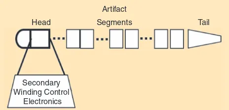
As can be seen in Figure 2, the robot can be divided into three main parts: the head, the segments, and the tail. The tail provides a significant contribution to the propulsion. It is a passive element that transmits the locomotion wave to the water with high efficiency. The segments are actuated by novel muscle-like actuators contained within a number of vertebras, which also host central pattern generator electron-ics and batteries. The vision and vestibular systems, the high-level control electronics, and the recharging device are all placed in the head. The head section represents the central computational unit. Placing all the above-mentioned compo-nents in the head was a big challenge considering the con-straints imposed by the project.
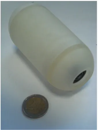
Figure 1. The head segment. The vision, the central board, and the secondary winding for the wireless charge system are placed inside this module.
Head (11 cm) Segments (55 cm) Tail (16 cm)
Device Overview
A transformer-like system that can transfer energy from a dock-ing station to a robot is described here. The system is a kind of transformer with a split core: 1) the primary coil (the source) and 2) the secondary coil (the receiver). Constraints due to the bioinspired approach during the artifact development are on the basis of the design of the device.
Low weight and low encumbrance are the most important features to be taken into account to host the secondary coil within the robot. The main criterion in the design is the max-imization of the ratios, transferred power versus weight, and size. Efficiency is of secondary importance for our purposes and is just considered for heating issues. The novelty of the
system is the hollow shape of the secondary magnetic core section in which the electronics can be hosted.
The inductive power transfer was chosen after considering the advantages and drawbacks of the systems in the literature.
Model
The secondary coil was modeled first to fit the constraints imposed by the size and shape of the robot, which is eel shaped and composed of many segments. The diameter is around 50 mm, and the length of the robot depends on the number of segments (Figure 3). The charging system is supposed to be placed in the head segment with a length of 70 mm.
For the secondary coil magnetic core section, two dif-ferent designs were considered to reduce the bulk and the weight and to maximize the transferred power. Figure 4 presents the two possible approaches. The two repre-sented metal cross sections have the same cross area, but Case 1 has a uniform metal core, whereas Case 2 has a hollow shape. Case 1 is sometimes used for underwater vehicles [8], [9]. However, this solution does not fit our case because of the constraints related to bioinspiration. For example, with the increase in the air gap, the magnetic inductance would be reduced too much, and the elec-tronic components would have to be placed around this structure, which would result in a difficult design.
On the other hand, Case 2 has more free room available for the electronics board, and the magnetic core is attached to the head shell, thus minimizing the gap with the external inductor. The resulting longitudinal section envisaged for the device is shown in Figure 5.
The secondary magnetic core section is separated from the primary section by a coupling interface, which is the air/water gap. The primary metal core section, consisting of six ele-ments, surrounds the secondary.
Design constraints are the overall dimensions and mass, turns, magnetic flux, and desired power. After a parametric study reported in the following, we chose the optimum working point for our application in terms of maximum delivered power to weight ratio. The primary coil was dimensioned after the secondary, but in this case, dimen-sions were not a constraint because coupling geometry (interface with the secondary magnetic core section) and electromagnetic flux generation were the only two require-ments. Again, we chose the best compromise between power, dimensions, and number of turns.
Equations and Dimensioning
Figure 6 shows dimensioning parameters of the cross section of the secondary core shape.
To design the secondary coil, we started with the sec-ondary coil core design. Equations (1) and (2) describe the core geometry in relation to the length and diameter, respectively. The magnetic flux flows from the primary coil to the secondary coil in the magnetic core, crossing the lit-tle air gap between the two (Figure 5). In the cross section
Head
Artifact
Tail
Secondary Winding Control
Electronics
Segments
Figure 3. LAMPETRA artifact. The first segment is the head-like section. This hosts the charging system and the control electronics. The total length of the robot is around 80 cm depending on the number of segments and on the tail length. Every segment implements magnetic muscle-like actuators [7] and local control electronics.
Usable Room
Case II
Robot Skin Case I
Figure 4. Comparison between the designs of the secondary magnetic core section. The room available and the coupling in Case 2 are better than in Case 1.
Primary Core Section Coupling Interface
Secondary Area for Coil Windings
Secondary Core Section
Magnetic Flux
(Figure 6), h and ( )c r , where r=b/2, are dependent vari-ables for the wire thickness and diameter of the device, respectively. These dependencies enable the magnetic flux to be maintained constant at each point of the magnetic core. We approximated these values to a constant size in this prototype.
The maximum number of turns ( )Nt was calculated using
(3) by varying the inner diameter ( )d and considering the fol-lowing values: external diameter ( )D 50 mm, diameter of iron strips ( )b 1 mm (r=b/ ),2 length ( )L of the device 60 mm, lated using (4) to estimate the output power (Powu) estimated in (6) and the current transferred to the secondary coil:
, maximum magnetic field for the given material, and lt is
the turn length. Relevant characteristics, plotted in Fig-ure 7, were evaluated to choose the dimension of the inner diameter. We chose the maximum power/mass ratio as working point.
The primary coil consists of a number of subcores (six) that surround the secondary coil. The primary coil was designed to ensure an adequate magnetic flux in the second-ary coil, by exploiting (1)–(6) and the following relations:
( )Ni D=0{. (7)
The general law governing the relation between the number of turns (ND), the current ( ),i and the magnetic
flux are represented by (7). The reluctance ( )0
calcu-lated by using (8) is an intrinsic value of the magnetic core, depending on its shape. Air reluctance is calculated by approximating the air gap size:
. 2
tot air/water sec pr
0 = 0 +0 +0 (8)
ND is calculated by using (9) considering the free space
around the magnetic core where W is the width of
wind-ing, L is the length, and Aw are “wing” dimensions (refer
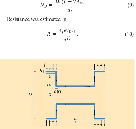
Figure 6. Secondary cylindrical magnetic core unit cross section. How the laminations were shaped for the secondary magnetic core section is shown. The external diameter ( ),D the column diameter ( ),b the wings for coupling with the primary core ( ),a
and length of the device ( )L are given data. The wing diameter ( ( ))h d and the winding area ( ( ))c r are dependent variables
0.01 0.02 0.03 0.04 0.05 0.06
Figure 7. Output power, voltage, current, number of turns, mass, and power/mass ratio are plotted as a function of the inner diameter d, considering the external diameter, the axial length, and the diameter of the wire (0.5 mm) as given. Arrow: the working point chosen, whereas the related obtained values can be found in Table 1.
Table 1. Working values obtained from the model.
Parameters Values (IU)
Nt, number of turns 560
Veff load in voltage 7.63 (V)
R, inner resistor 7.07 (X)
Ieff load, current 1.08 (A)
Powu, output power * 8.23 (W)
M, mass * 0.22 (kg)
Pows, power/mass ratio * 36 (W/kg)
Marked (*) parameters are not dependent on the wire diameter (df). Other parameters are strictly related to df. The wire diameter
Materials and Methods
Secondary Module
As already mentioned, the secondary coil dimensions are
approximately 50 mm in diameter and 60 mm !2 mm in
length. Off-the-shelf materials were chosen as building elements. Materials:
● iron wire (1.2 mm diameter)
● Delrin
● copper wire (0.5 mm diameter)
● epoxy material.
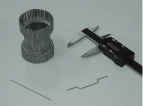
The iron wire was shaped into curved laminations (Figures 8 and 9) in accordance with the transformer theory. In fact, using a low-frequency magnetic field (50 Hz), hysteresis losses and eddy currents can influence the device by generat-ing side effects in the magnetic core. To reduce these effects, which may decrease the efficiency of the device, the magnetic core needs to be built with lamination-like elements.
We used a Delrin core to assemble the metal laminations in the cylindrical-shaped ending (Figure 10). Epoxy material was used to create a rigid structure and to provide electronic insu-lation. The magnetic core received further electric insulation by means of insulating lacquer. The module was then wound in copper wire. More than 500 windings were utilized. Weight, resistance, and dimensions were checked after fabrication.
Primary Module
The primary unit was developed by following similar design criteria to those adopted for the secondary side, particularly with regard to the maximum magnetic induction available in the material and target voltage. The module is composed of six radial coils (Figure 11), generating a magnetic flux, and poles are located with a small radial gap at the ends of the sec-ondary module. Epoxy material was used to link iron pieces in the six cores. Coils were made by using a wire with a diam-eter of 0.8 mm, which gives an impedance for the six coils in series that matches the voltage given by a commercial transformer, as detailed in the following.
After preliminary tests on overall functionality, the mod-ule was embedded in polyurethane (PU) to strengthen the structure, increase the heat dissipation, and make the system waterproof. The device will also be coated with a special lac-quer paint to obtain a smooth surface and to ensure complete isolation when underwater.
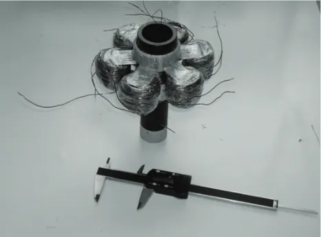
Experiments
Once the final prototype was ready (Figure 12), experi-ments were performed to verify compliance with the model and to characterize the device. Particular attention was paid to the testing of the output power supplied by the secondary coil. Table 2 summarizes the main charac-teristics of the system.
The complete device is powered by an external worksta-tion and works at 48 V and 50 Hz. The most important value to investigate is the maximum output power of the second-Figure 8. The final and intermediate shape of the iron wire.
Figure 9. Iron wire modeling. About 200 laminations were crafted for the entire device. A simple but stable setup was built to ensure constant dimensions for all the laminations.
ary coil. The output power is maximum when load imped-ance equals the conjugate inner one according to the maxi-mum power transfer theorem. An oscilloscope (Figure 13) was used to measure the voltage at the ends of a load: this is a series of resistors and capacitors whose resulting impedance is close to the conjugate of inner resistance and inductance.
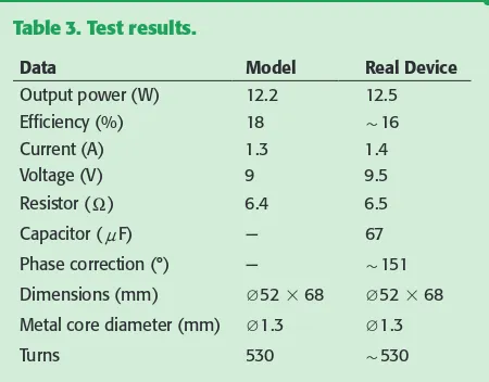
The results of the tests are summarized in Table 3. The “Real Device” column shows the experimental data obtained with the device, and the “Model” column shows the data on the theoretical dimensions retrieved using the model. The real values are very close to the parameters obtained with the model. Finally buoyancy, as given by the Archimedes princi-ple, was estimated: the mass of the secondary device is 200 g, and its overall volume is 145 cm3; therefore, a negative trim of 75 g is present and must be negotiated by exploiting small additional adjacent empty spaces.
The efficiency, as reported on Table 3, is roughly 16% and is close to the estimated value. The low efficiency of the device is due to the design in terms of operating frequency and also the handmade lamination and windings. Efficiency
can be increased by tuning the frequency and by improving the magnetic core. On the other hand, the aim of this device is not to be highly efficient, above all to be suitable for bioin-spired purposes in water environment and to be safe. From this point of view, the device works as expected and is fully compatible with the electronics and all other robot compo-nents. Finally, the energy requirements of the robot are very low (power consumption is less than 5 W, and battery capacity on board is only 20 Wh) and therefore energy before conversion is also very limited.
Discussion
The primary coil can theoretically work up to a standard volt-age of 220 V at 50 Hz; however, it can work at a lower voltvolt-age and was developed to operate at 48 V. By reducing the voltage: 1) the device is less dangerous in a water environment, 2) the energy required is lower, and 3) the heat dissipation decreases. The work frequency is also an important parameter. Although an increase in frequency improves the performance of the device, the design proposed here works at 50 Hz, considering the international standard frequency (50–60 Hz); the device can thus be plugged in easily everywhere. These design choices
Tek
M 10.0 ms
M Pos: 0.000s Measure
CH1 RMS 9.03 V
CH1 None 1
CH1 Peak–Peak
27.8 V
CH1 None
CH1 5.00 V CH1/4.80 V
CH2 Off Freq. Stop
Figure 13. Output voltage amplitude is approximately 14 V.
Figure 12. Final result before coating.
Table 2. Summary of working values obtained from the model.
Data Secondary Primary Primary + PU
Mass (kg) 0.206 1.805 3.702
Resistor (X) 6.5 10 10
Electrical
Isolation Yes Yes Yes*
Dimensions (mm)
Q50 # 68 Q115 # 68 178 # 173 # 83
Air/water gap
max (mm) — 2 1.5
*Waterproof.
are strictly related to the low efficiency of the device compared with the traditional transformers that can achieve a very high efficiency up to 95%. The air/water gap, the low working fre-quency, and the manufacturing process reduce the efficiency to 16%. This value is acceptable for our application in which external power is not an issue. Furthermore, the concept and the design are still valid, although applications would require higher performance and efficiency.
Another important feature is the hollow shape of the secondary core section. Using this design, electronics can be placed into the secondary coil magnetic core, thus limit-ing any wasted space. This design also reduces the weight, which is an important parameter in underwater applica-tions when a neutral trim is required.
The secondary coil final mass is 200 g. Considering the total length (and volume) of the artifact, this low weight enables the buoyancy of the robot to be designed, thus not having to take into account the weight of the secondary coil.
Finally, the expected self-docking feature has been observed. The secondary coil is attracted into the primary coil with a delicate force of about 0.5 N. This function is not mandatory for our application, where we have locomotion capability; however, it is still useful as additional self-guid-ance while docking.
Conclusion
We have successfully developed a low-weight system for bat-tery charging by proposing a new design for wireless power transfer devices. Our design is useful in situations when there are constraints regarding: small dimensions, a cylindri-cally shaped robot, low weight, and high electrical insulation. Another advantage is that only one primary coil is needed to charge different robots equipped with individual secondary coils. Robot docking is critical and our device provides a neat solution with self-guidance. All these features highlight that our device would work well in AUV applications.
During the tests, the device did not cause any damage to the electronics when the magnetic field was applied. The device will be shortly integrated into the whole system.
Acknowledgment
This work is primarily being carried out under the Euro-pean Project LAMPETRA (Life-like Artifacts for Motor-Postural Experiments and Development of new Control Technologies inspired by Rapid Animal locomotion) Proj-ect Reference: 216100 through the Seventh Frame Program research area: ICT-2007.8.3-FET “Bio-ICT Convergence.” It also comes under the European Project ANGELS (ANGuil-liform robot with ELectric Sense) Project Reference: 231845 through the Seventh Frame Program, research area: ICT-2007.8.5-FET “Embodied intelligence.”
References
[1] C. Stefanini, S. Orofino, L. Manfredi, S. Mintchev, S. Marrazza, T. Assaf, L. Capantini, E. Sinibaldi, S. Grillner, P. Wallen, and P. Dario, “A novel auton-omous, bioinspired swimming robot developed by neuroscientists and bioen-gineers,” Bioinspiration Biomimetics, vol. 7, no. 2, p. 025001, 2012.
[2] S. Grillner, A. Kozlov, P. Dario, C. Stefanini, A. Menciassi, A. Lansner, and J. H. Kotaleski. (2007). Modeling a vertebrate motor system: Pattern genera-tion, steering and control of body orientation. Prog. Brain Res. [Online]. 165(14), pp. 221–234, PMID: 17925249. Available: http://www.ncbi.nlm.nih. gov/pubmed/17925249
[3] A. J. Ijspeert, J. Hallam, and D. Willshaw. (1999, Mar.). Evolving swimming controllers for a simulated lamprey with inspiration from neurobiology. Adapt. Behav. [Online]. 7(2), pp. 151–172. Available: http://adb.sagepub.com/ cgi/content/abstract/7/2/151
[4] A. Crespi, A. Badertscher, A. Guignard, and A. J. Ijspeert, “AmphiBot I: An amphibious snake-like robot,” Robot. Auton. Syst., vol. 50, no. 4, pp. 163–175, 2005.
[5] R. Stokey, M. Purcell, N. Forrester, T. Austin, R. Goldsborough, B. Allen, and C. von Alt. (1997). A docking system for REMUS, an autonomous under-water vehicle. presented at OCEANS MTS/IEEE Conf. Proc. 2, pp. 1132–1136. [Online]. Available: 10.1109/OCEANS.1997.624151
[6] R. Coulson, J. Lambiotte, G. Grenon, T. Pantelakis, J. Curran, and A. An. (2004). Development of a modular docking sub-system for 12" class autonomous underwater vehicles. presented at OCEANS MTTS/IEEE TECHNO-OCEAN. 3, pp. 1745–1749. [Online]. Available: 10.1109/OCEANS.2004.1406388
[7] C. Stefanini, S. Mintchev, and P. Dario, “Permanent magnet actuator for adaptive actuation,” Patent WO 0 15 997, Feb. 11, 2010.
[8] B. Heeres, D. Novotny, D. Divan, and R. Lorenz. (1994). Contactless under-water power delivery. presented at IEEE Power Electronics Specialists Conf. PESC Rec. 25th Annu. 1, pp. 418–423. [Online]. Available: 10.1109/ PESC.1994.349700
[9] A. Bradley, M. Feezor, H. Singh, and F. Y. Sorrell. (2001). Power systems for autonomous underwater vehicles. IEEE J. Ocean. Eng. [Online]. 26(4), pp. 526– 538. Available: 10.1109/48.972089
Tareq Assaf, Scuola Superiore Sant’Anna, Pontedera 56025, Italy. E-mail: [email protected].
Cesare Stefanini, Scuola Superiore Sant’Anna, Pontedera 56025, Italy. E-mail: [email protected].
Paolo Dario, Scuola Superiore Sant’Anna, Pontedera 56025, Italy. E-mail: [email protected].
Table 3. Test results.
Data Model Real Device
Output power (W) 12.2 12.5
Efficiency (%) 18 +16
Current (A) 1.3 1.4
Voltage (V) 9 9.5
Resistor (X) 6.4 6.5
Capacitor (nF) — 67
Phase correction (°) — +151
Dimensions (mm) Q52 # 68 Q52 # 68
Metal core diameter (mm) Q1.3 Q1.3