Towards innovative FRP fabric reinforcement
in concrete beams: concrete
–
CFRP bond
Mithila Achintha
Faculty of Engineering and the Environment, University of Southampton, Southampton, UK (corresponding author: [email protected]) Fikri Alami
Faculty of Engineering and the Environment, University of Southampton, Southampton, UK
Sian Harry
Faculty of Engineering and the Environment, University of Southampton, Southampton, UK
Alan Bloodworth
School of Engineering, University of Warwick, Coventry, UK
The paper reports results of an experimental investigation into load response and failure behaviour of rectangular prismatic concrete beams reinforced with a combined flexural and shear reinforcement system made from carbon-fibre-reinforced polymer (CFRP) fabric. It is shown that CFRP U-channels with aggregate coating and an anchorage system consisting of a lipped channel section with intermittent closed loops were found to provide improved composite action between the CFRP reinforcement and concrete. These CFRP channels also ensured adequate strength and ductility before failure. Possible modes of failure of the beams are discussed, as is the effect of the design parameters on the failure mode and the failure load. It is anticipated that the findings of this paper could be effectively used in other applications such as non-prismatic concrete geometries and as permanent formwork/reinforcement in thin concrete members where the flexible characteristics of dry CFRP fabrics are most useful.
Introduction
Interest in fibre-reinforced polymer (FRP) internal reinforce-ment in concrete is mostly focused on its use as a way to miti-gate the corrosion seen in conventional steel-reinforced concrete structures exposed to the environment, such as highway bridges and sea walls (Achintha, 2009). Superior mechanical properties, high tensile strength and light weight mean FRPs are attractive in civil engineering structures. The non-magnetic properties of FRPs also make them useful for facilities for magnetic resonance imaging (MRI) medical equipment, airport runways, electronics laboratories and so on. FRP internal reinforcements have mostly been used in the form of reinforcement bars (e.g. Manalo et al., 2014; Qin et al., 2017), but other reinforcement systems such as grids, fabrics and ropes have also been sparsely used (Gudoniset al., 2013). Commercially available FRP reinforcement systems are mostly made from glass (GFRP) or carbon (CFRP) fibres embedded in a resin matrix.
The FRP-reinforced concrete design guidelines published by national and international professional organisations (e.g. ACI 440.1R-15 (ACI, 2015); CAN/CSA-S806-12 (CSA, 2012); fib Bulletin No. 40 (fib, 2007)) are mainly given in the form of modifications to the existing limit state design principles adopted in steel-reinforced concrete codes of practice. The modifications generally take into account the intrinsic mechan-ical properties of FRPs, and are mostly empirmechan-ical equations developed based on experimental investigations. However, the use of FRPs as a direct substitute for steel bars using the same design principles as in steel-reinforced concrete members means designs are often expensive and inefficient
(Bank, 2006). There are fundamental differences between the characteristics of the two materials: FRPs are elastic and brittle, whereas steel yields under high stresses. There are also major differences in the bond characteristics, with steel bars having a strong concrete–steel bond, which is advantageous because when the strain in the steel reaches the yield strain at a crack in the concrete, the steel yields and no stress concen-tration can occur. In contrast, failure of FRPs may be trig-gered by high local strains. The existing FRP internal reinforcement design guidelines are being linked to FRP bars, and the guidelines are often too conservative (Bank, 2006).
The flexible nature of FRP fabrics prior to curing with resins provides the prospect of forming novel, efficient two-dimen-sional (2D) and three-dimentwo-dimen-sional (3D) reinforcement systems. Wide ranges of mechanical properties, to match the design requirements, can be obtained by combining fabric sheets in different laminate arrangements. Despite the potential of FRP fabrics to reinforce concrete, only a little research, largely exter-nal strengthening of concrete beams and columns, has been reported (e.g. Punuraiet al., 2013). Despite the high material cost of FRPs compared to traditional reinforcing materials, the economic benefits may come from lower maintenance require-ments and longer life. Total life-cycle analyses and environ-mental impact assessments may be used to justify the economic viability of FRPs in the construction industry (Achintha, 2016).
in concrete beams. The paper reports results of an experimen-tal investigation of the bond behaviour of concrete beams reinforced with three different CFRP fabric reinforcement con-figurations: a plain U-channel; a U-channel with an aggregate coating (i.e. a layer of aggregate applied on all surfaces of the CFRP channel using an epoxy resin and allowed to cure prior to casting concrete); and an anchorage system consisting of a lipped U-channel section with intermittent closed loops. Possible modes of failures of the beams are discussed, as is the effect of the aggregate coating on FRPs and anchorages on the failure mode and the failure load. It is anticipated that the basis provided by the present work could be effectively used in applications such as combined flexural and shear reinforce-ment systems in structurally optimised, non-prismatic concrete members cast using flexible formwork (e.g. Orr, 2012) and as permanent formwork in novel forms of thin-shell concrete flooring system (e.g. Hawkins et al., 2017) for multi-storey buildings, where both applications have the potential to create low embodied energy alternatives to respective traditional reinforced concrete applications.
Biaxial CFRP fabric reinforcement
Over-reinforced designs are preferred in FRP–concrete design guidelines as a mean of mitigating potential brittle failure of FRPs. Nevertheless, the resulting compression failure of con-crete is still brittle, and it is not favoured in the construction industry. There is a need for innovative and cost-effective FRP reinforcement systems that will ensure sufficient ductility in concrete structures while enabling the efficient use of high strength/strain capacities of FRPs. The existing FRP reinforce-ment systems are largely unidirectional. These systems are prone to brittle material/bond failures. Multi-directional FRP fabrics have the potential to provide reinforcement systems that will have greater strength and ductility in more than one direction. For example, 0° fibres in a multi-directional laminate can provide high strength/stiffness properties along the fibre direction, whereas 90° fibres will enhance the mechanical prop-erties in the transverse direction. On the other hand, ±45° fibres provide high in-plane strength and strain properties.
Fibre-reinforced polymer fabrics have great potential to lend themselves to any required geometry and to provide mechan-ical properties that match the design requirements. Previous studies on the use of multi-directional FRP fabrics in strength-ening concrete beams and columns (Punuraiet al., 2013), FRP fabrics–fine-grained concrete thin layers for retrofitting of con-crete beams (Brückner et al., 2006), in thin-walled concrete facades (Shams et al., 2014) and so on, have demonstrated benefits such as ductile failure compared to equivalent appli-cations of conventional FRP bars or unidirectional pre-impreg-nated fibre sheets. In the current study, a single combined flexural and shear reinforcement system was investigated for concrete beams. ±45° multi-layer CFRP fabric reinforcement systems were investigated, owing to the potential of ±45°
fabrics to ensure greater ductility in the beams. As the long-term performance of GRFP under some especially harsh environmental conditions–such as exposure to high alkalinity, seawater or deicing salts – remains unknown (Robert and Benmokrane, 2013), CFRP fabrics were chosen in the current study.
Concrete
–
FRP bond
Concrete–FRP bond is the single most important parameter that governs load response and failure behaviour of FRP reinforced concrete beams. The characteristics of the concrete– FRP bond have been extensively studied in the literature, mostly using the experiments of pull-out tests of FRP bars in concrete (e.g. Achillides and Pilakoutas, 2004; Aiello et al., 2007). Limited research on bending tests that represent FRP as flexural reinforcement in concrete beams has also been reported (e.g. Ashtianiet al., 2013). The poorer bond perform-ance of the concrete–FRP bars when compared to steel reinforcement is well known (Larralde and Silva-Rodriguez, 1993). Different types of surface deformation systems of the FRP, in particular, sand-coated FRP bars, are known for their promise in enhancing bond strength while eliminating prema-ture debonding failure (Baenaet al., 2009).
The technique of sand coatings on FRPs has not been widely explored for 2D/3D internal FRP reinforcement systems such as CFRP channels. The limited applications of sand/aggregate coatings has primarily been on tensile/shear pull-out exper-iments of FRP laminate coupons; experimental investigations suggested improved bond strength and less brittle failure behaviour (e.g. Choet al., 2010; Liet al., 2014; Wanget al., 2014). The improvements in the composite action between FRP and concrete may be attributed to mechanical interlock-ing and the improved bond between aggregate coatinterlock-ing and the cement paste (Li et al., 2014; Wanget al., 2014). The feasi-bility of epoxy-bonded aggregate coatings to improve compo-site action between concrete and FRP has also been demonstrated in applications of pultruded FRP planks as per-manent formwork in concrete–FRP hybrid bridge decks (Bank et al., 2007).
was also noted (Cho et al., 2010); nevertheless, the reported results are insufficient to establish verified conclusions.
Anchorage mechanisms for preventing premature debonding of the concrete–FRP bond
Premature failure of the concrete–FRP bond is common in all concrete–FRP hybrid systems; debonding usually triggers at high stress concentration features or at locations where inter-face cracks/flaws are present. Despite the significant improve-ments in bond properties of aggregate-coated FRP–concrete bond, debonding was not completely eliminated (e.g. Bank et al., 2007; Li et al., 2014). Debonding was also noted with sand-coated FRP bars (Cosenza et al., 1997) as well as in externally bonded FRP systems on concrete beams for flexural/shear strengthening/retrofitting purposes (Achintha and Burgoyne, 2012). Extensive research on debonding of externally bonded FRPs from concrete has identified that pro-vision of anchorages in the vicinities where the FRP curtails has potential to eliminate debonding and to improve the overall structural performance (Grelle and Sneed, 2013).
Experimental programme
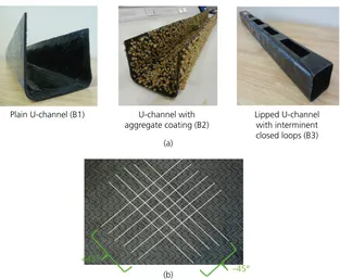
In the first half of the experimental programme, three concrete beams, each with dimensions 1000 mm (long)120 mm (wide)120 mm (deep), reinforced with three different forms of CFRP fabric reinforcement were tested: a plain U-channel (B1); a U-channel with aggregate coating (B2); and an ancho-rage system consisting of a lipped U-channel with intermittent closed loops (B3) (Figure 1(a)). Aggregate coating was used as
a means of improving the composite action between concrete and the CFRP reinforcement, whereas a lipped channel section with intermittent closed loops was chosen to eliminate premature debonding that may originate at the top edges of the U-channel. After taking into account the results of these three beams, a beam reinforced with a lipped CFRP U-channel with intermittent closed loops and an aggregate coating on all internal and external surfaces (B4) was designed and tested in the second half of the experimental programme as a means to achieve stronger and stiffer beams with improved post-breakage strength and ductility. For comparison of the results, a reference beam (B5) of the same dimensions as B4, but with a plain CFRP U-channel, was also fabricated and tested. The objective of this experimental programme was not to provide design data but to demonstrate the basic mechanics of concrete beams reinforced with CFRP fabric reinforcement. Although a combined flexural/shear reinforcement system was provided, the experiments aimed to investigate the flexural behaviour of the beams. A detailed shear analysis of the beams was beyond the scope of the study; however, an approximate shear design was used to ensure no premature shear failure prior to the expected flexural failure. The design of the CFRP fabric reinforcement systems was not trivial; the analyses adopted in the current study will be presented in a future publication.
Materials
All three test beams were made using the same materials, fabri-cation techniques and curing conditions. The CFRP channels
Plain U-channel (B1) U-channel with aggregate coating (B2)
Lipped U-channel with interminent closed loops (B3)
+45°
–45° (b)
(a)
were first fabricated and then concrete was cast once the CFRP channels had fully cured.
±45° biaxial carbon fibre dry fabric (Figure 1(b)) (weight 300 g/m2and thickness 0·35 mm), purchased from a commer-cial supplier, was used to fabricate the reinforcement channels. Four plies of dry CFRP fabrics were first individually impreg-nated with an epoxy laminating resin in combination with a slow hardener using a wet lay-up fabrication technique and then layered each one on top of the other in order to fabricate a four-layer laminate. A slow hardener was chosen because of longer workability time and the flexibility it provided for fabri-cating U-channels. With a dry fabric thickness of 0·35 mm and a total resin thickness of 0·25 mm, the thickness of the laminate was 1·65 mm. The laminate was symmetric, as for each layer on one side of the mid-plane there was a correspond-ing layer at equal distance from the mid-plane on the other side with identical elastic mechanical properties and layer thickness; this ensures no coupling between in-plane loading and bending deformations. Similarly, the laminate was balanced because it had pairs of layers with identical elastic mechanical properties and thicknesses, but with +45° and−45° fibre orientations with
respect to the longitudinal axis; this eliminates coupling between normal loading and in-plane shear deformations.
The concrete mix was designed in accordance with the BRE design manual (BRE, 1997). A high slump (60–180 mm) and small aggregate (10 mm maximum size) were chosen to ensure the workability required to cast the beams of small dimensions. Fine aggregate with 100% passing through a 600μm sieve was used. Concrete was cast in situ in accordance with the require-ments specified in BS EN 206 (BSI, 2013). The average 28 d compressive strength of the concrete was determined to be 38 MPa.
CFRP fabric reinforcement systems
Plain U-channel
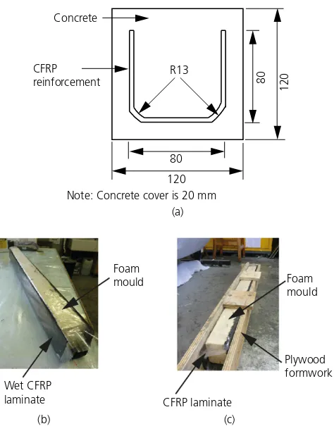
The plain U-channel was fabricated from 970 mm230 mm CFRP fabric sheets in order to achieve the dimensions 970 mm80 mm80 mm of the channel (Figure 2(a)). The required U-shape was obtained by wrapping the wet, rectangu-lar laminate around a foam mould (Figure 2(b)). The CFRP-wrapped foam mould was then positioned within a plywood formwork (Figure 2(c)) and cured in ambient conditions (20±2°C) for 2 d. Thin release films that leave no residues were used between the CFRP and the foam, and also between the CFRP and the plywood. In order to limit the effects of stress concentrations, the corners of the channel were rounded. Although autoclave or resin infusion techniques have the potential to produce products of higher quality than the wet lay-up method used here, advanced manufacturing methods were beyond the scope of the study, as the objective was to demonstrate the use of novel forms of fabric reinforcement in concrete beams.
U-channel with aggregate coating
The aggregate-coated CFRP channel adopted the same section dimensions, manufacturing and curing methods as the plain U-channel. However, once the CFRP had cured, an aggregate coating was applied on all internal and external faces (Figure 1(a)). The size of the aggregate particles and the surface density were chosen to achieve desirable benefits.
Size and spatial distribution of aggregate coating
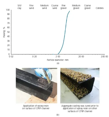
Aggregate of size 2–5 mm was chosen considering the improved bond properties and the favourable concrete substrate failure reported in the literature for coating with particles of this size range. Dried quartz gravel purchased from a commer-cial supplier was used. Figure 3(a) shows the distribution of the particle size, obtained from a sieve analysis conducted in accordance with BS 1377: Part 2 (BSI, 1990) using an auto-matic sieve shaker (vibration amplitude 5·5 mm and over a 10 min duration) with sieve sizes 1·18 mm, 2·00 mm, 3·35 mm, 5·00 mm and 6·30 mm. As can be seen from Figure 3(a), the particles were within the required size range (2–5 mm). Particles less than 1·18 mm in size (only 0·16% by weight of total particles) were removed, because such small particles had not been previously used in aggregate coatings. Approximately
80
Note: Concrete cover is 20 mm
Wet CFRP
50% surface distribution density of aggregate coating was chosen as a reasonable starting point in the investigation, in order to achieve improved bond properties while providing ade-quate space for mechanical interlock between the coating and in situ concrete. The volume of aggregate required for 50% coverage of the total surface area of the CFRP channel was determined by using the knowledge of the volume of aggregate required for an approximately 100% surface coverage of a known surface area of the CFRP. In the present study, one-sixth of the required total volume of aggregate was applied on all surfaces of each one-sixth length of the CFRP channel.
Application of aggregate coating
The same epoxy resin and the mix ratio used in the CFRP channels was also used to bond the aggregate on the surfaces of the CFRP channel. The thickness of the resin layer was maintained to be 0·5 mm in order to achieve a sufficient
submersion of the aggregates while eliminating complete cover-age of aggregate (a‘smoothing’effect caused by the full cover-age of epoxy on aggregate can weaken the CFRP–concrete bond (Banket al., 2007)). The aggregate coating was applied on two horizontal surfaces at a time (see Figure 3(b)), and once the resin adhesive had fully cured (usually after 24 h), the coating was applied on another two surfaces of the CFRP channel (see Figure 3(b)). Generally, an even layer of aggregate was applied on all surfaces, although owing to the curvature at the corners of the channel, small slippages and movement of the aggregate were unavoidable.
Lipped U-channel with intermittent closed loops In order to investigate the effect of anchorage at high-stress locations of the concrete–CFRP bond, a lipped U-channel with intermittent closed loops was investigated (Figure 1(a)). Conversely to the other two channels, this CFRP channel was 100
90
80
70
60
50
40
30
20
10
0
Passing: %
0·02 0·20 2·00
Particle diameter: mm (a)
20·00 200·00
Silt/ clay
Fine sand
Medium sand
Coarse sand
Fine gravel
Medium gravel
Coarse
gravel Cobbles
(b) Application of epoxy resin
on surface of CFRP channel
Aggregate coating was cured prior to application of epoxy resin on other
surfaces of CFRP channel
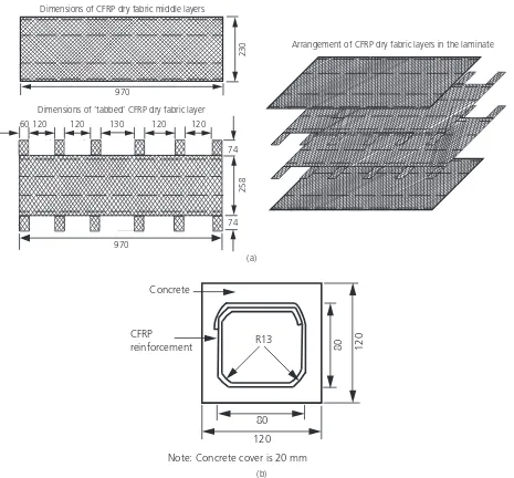
made using two dry fabric plies of size 970 mm230 mm and two larger plies of size 970 mm332 mm. The larger plies were cut on each side to create a series of anchorage tabs (each 60 mm wide and 74 mm long), as shown in Figure 4(a). When stacking the plies during the wet lay-up process, tabbed plies were positioned in the middle, with others located on the top and bottom, as shown in Figure 4(a). Tabs on one side of the laminate were first wrapped over the foam mould, and then those on the other side were wrapped over the first to make the required intermittent closed loops (Figure 4(b)). Intermittent gaps of 120 mm40 mm in plan were left between the closed loops in order to facilitate concrete casting. The CFRP channel was cured in the same way as the other two channels.
Concrete beam casting and test set-up
Two linear strain gauges (gauge length6 mm and grid resist-ance 120±0·3Ω) were fixed along the two fibre directions at midspan of each CFRP channel on the bottom surface. Although strain gauge rosettes would have been an alternative, the relatively large rosette could weaken the surrounding con-crete–FRP bond; therefore, strain gauges much smaller than a rosette were used. In order to improve the bond between plain CFRP channels and in situ concrete (i.e. in B1 and B3), a thin, wet, epoxy resin layer was applied 45 min prior to concrete casting on all surfaces of the CFRP channels. No epoxy resin was applied to the aggregate-coated channel (B2) in order to eliminate potential ‘smoothing’ of the aggregate
230
970
258
970
74
74
60120 120 130 120 120
Dimensions of CFRP dry fabric middle layers
Dimensions of ‘tabbed’ CFRP dry fabric layer
Arrangement of CFRP dry fabric layers in the laminate
(a)
(b) 80
120
80 120 R13
Concrete
CFRP reinforcement
Note: Concrete cover is 20 mm
surfaces. The three concrete beams were cast and cured in ambient conditions.
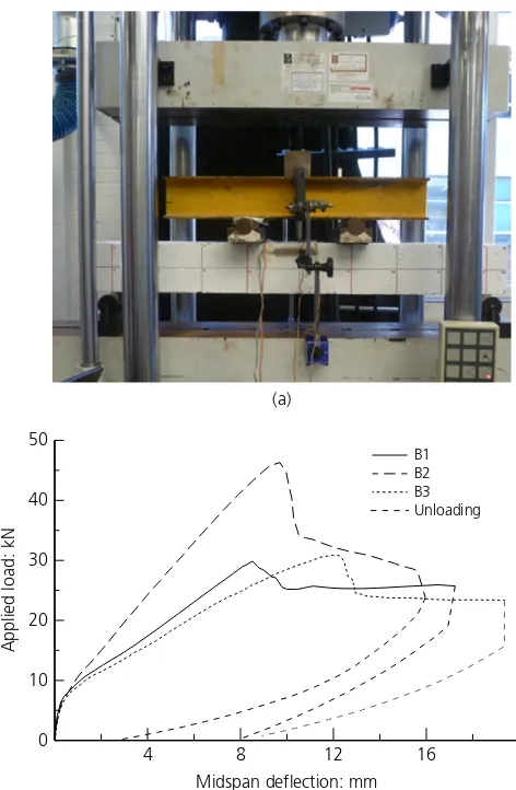
Beams were tested after 28 d of curing in four-point bending (Figure 5(a)) (shear span = 325 mm, constant moment zone = 250 mm) using a servo-hydraulic test machine, displacement controlled (stroke rate of 2 mm/min). Midspan deflection was measured using two digital displacement gauges, located at the front and back of the beam.
Experimental results
Load–midspan deflection relationship
Figure 5(b) shows load–midspan deflection relationships of the three beams. As expected, the behaviours of the three beams were similar within the uncracked regime of concrete. The results suggest that in all beams flexural cracks first developed at applied load 7·5 kN, where the corresponding midspan deflection was 0·6 mm. As expected, after the formation of flexural cracks, beams showed a reduction in flexural stiffness.
As can be seen from the figure, B2 demonstrated a higher bending stiffness and failure load compared to B1 and B3. This suggests an improved bond and composite action between concrete and CFRP in B2. The peak load of46·65 kN of B2 is significantly higher than those of 29·88 kN and 30·86 kN of B1 and B3, respectively.
Ductility
Since the tests were conducted with displacement controlled, the post-peak behaviour of the beams was also observed (Figure 5(b)). All beams resisted the applied load beyond the peak load, demonstrating notable ductility before final failure. The beams failed at loads 25·90, 23·74 and 23·38 kN, respect-ively; 86·7, 50·9 and 75·8% of the respective peak loads. The midspan deflections of the beams at the respective failure loads were 17·2, 15·9 and 20·2 mm, whereas deflections at the respective peak loads were 8·5, 9·7 and 12·2 mm. ‘Ductility index’ may be defined as the ratio of the additional midspan deflection after the peak load to the midspan deflection at the peak load; ductility indices of the three beams are 102·4, 63·9 and 91·6%, respectively. The results suggest that, unlike con-ventional applications of FRP bars and other FRP internal reinforcements in concrete beams where brittle failures are inevitable, beams B1, B2 and B3 demonstrated significant ductility and safe failure behaviour. A further advantage of the beams may be explored: the beams recovered the deflection upon unloading, as shown in Figure 5(b). The residual midspan deflections of the three beams were 7·9, 2·6 and 8·9 mm, respectively (the corresponding recovery of the midspan deflection from the failure load was 54·1, 83·6 and 55·9%). This suggests that a large part of the energy put into the beam during loading has dissipated rather than being stored as strain energy; this ensures no explosive failure.
Analysis of failure
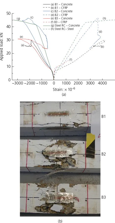
Figure 6(a) shows the applied load–strain relationships at midspan of all three test beams. Strains at the top surface of the beam (i.e. compression surface) and the strain in the CFRP along the fibre direction are shown in the figure. As noted previously, CFRP strain was measured along both fibre directions (+45° and −45°); the two CFRP strain
measure-ments were largely similar in each beam. As a detailed investi-gation of the 2D strain behaviour of the CFRP channel is beyond the scope of this paper, the average of the two measured strains is shown in Figure 6(a).
Strain in CFRP
As expected, the CFRP experienced higher strains after the development of flexural cracks in the beams. It should be noted that, owing to the failure of strain gauges, the CFRP strain in B3 was recorded only up to an applied load of 14·95 kN. Figure 6(a) shows that the CFRP strains at the peak loads of B1 and B2 were 0·00418 and 0·0036, respectively, and then the strains dropped after the peak load. In a previous
4 8 12 16
0 10 20 30 40 50
B1
B3 B2
Unloading
Midspan deflection: mm
Applied load: kN
(a)
study by the authors (Achinthaet al., 2015), it was noted that tensile and shear failure strains of the same CFRP laminate were greater than 0·016. Thus, the results suggest that the CFRP did not rupture in the beams.
Strain in concrete
As can be noted from Figure 6(a), the compressive strains at the peak load of the three beams were 0·001869, 0·002617 and 0·002990, respectively. The observation of the failure mode of the beams (Figure 6(b)) suggests the concrete compression zone failed in all beams. However, the noted strains in the
concrete (Figure 6(a)) at the peak loads are significantly lower than the expected ultimate compressive strain of concrete (0·0035) (Eurocode 2 (CEN, 2004)). Test results of a steel-reinforced beam made from the same concrete and tested as a control beam in the current study confirmed a concrete failure strain of0·0033 (see Figure 6(a)). The results suggest that the failure of B1, B2 and B3 was not conventional concrete com-pression failure, as described presently.
Crack patterns
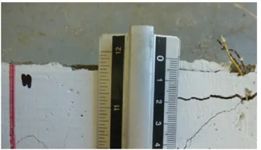
All beams showed similar even distribution of flexural cracks within the constant moment zone and a nominal number of minor cracks within shear spans. All beams exhibited horizon-tal ‘splitting’cracks on the top and side surfaces (Figure 7). Visual observations during testing confirmed that ‘splitting’ cracks on the top surface occurred prior to the development of horizontal ‘splitting’ on the sides of beams. The ‘splitting’ cracks on the top surface were first observed after the peak load; for example, top surface‘splitting’cracks on B2 and B3 were first observed at load 42 kN and 28·2 kN, respect-ively, during the post-peak regime (note: observations were not made during the testing of B1). Analysis of crack patterns suggests that all beams underwent similar failure mechanisms.
Failure mechanism
Under bending, the top surface region of the constant moment zone of the beams was subjected to high axial compression forces. In concrete, forces are mainly transferred from aggre-gate to aggreaggre-gate, which are randomly distributed. Under uni-axial compression, tensile forces develop in the lateral direction in order to balance the lateral component of the compressive force between adjacent aggregates that are essen-tially not aligned along a direction parallel to the longitudinal axis of the beam. Coalescence of microcracks and unstable growth of microcracks around the aggregate usually starts at an applied stress of 90% of the peak compressive stress (strain 0·0014) (Hsu et al., 1963). In the beams, the top of the CFRP channel was located 20 mm below the top surface of the beam. A weak bond between concrete and CFRP, and flaws/voids larger than those normally expected in pure con-crete are expected in the vicinity where the vertical sides of the CFRP channels were terminated. Thus, as noted in the exper-iments (Figure 7), development of major cracks in the com-pression zone, just above the CFRP curtailment location, parallel to the beam length (i.e. perpendicular to the lateral tensile stress) is expected under continued increase in the applied load. As can be seen in Figure 7, the major crack locations on the top surface in B1 and B2 were offset by 20 mm from the beam edge and there was40 mm offset in B3; these offset distances are comparable to the location of the top edge of the CFRP channel.
It should be noted that the concrete cover spalling off once flexural cracking has occurred did not happen in the beams B1
B2
B3
(b) (a)
−3000 −2000 −1000 0 1000 2000 3000 4000 0 (g) Steel RC – Concrete (h) Steel RC– Steel
Figure 6. (a) Applied load–strain relationships at midspan of the
tested in this study. This behaviour may be attributed to the bond improvement mechanisms used in the beams (i.e. appli-cations of (a) an epoxy layer (beams B1, B3 and B5) and (b) an aggregate coating (beams B2 and B4) on all surfaces (including the outer surfaces) of the CFRP channel); and the failure occurred in the compression zone of the beam. A detailed study of the potential danger of cover spalling off once flexural cracking occurs and the effects of freezing and thawing on spalling is beyond the scope of the present paper.
Narrow concrete compression zone
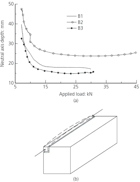
Figure 8(a) shows the neutral axis depth (pre-peak load regime only) measured from the top surface of the beam, calculated based on an assumed linear strain distribution at midspan
through the beam section and using the strain values measured on the concrete at the top surface and on the side of the beam 20 mm below the top surface. Although the use of closely spaced strain readings (on top and 20 mm below that) where the top strain gauge was at the beam centreline, while the other was on the side surface with 60 mm offset from the cen-treline to infer the through-depth strain profile, may only provide an approximate estimate of the neutral axis depth, the authors believe the neutral axis data shown in Figure 8(a) may still be reasonably accurate for the purpose of comparison. For brevity, only neutral axis depth at relatively high applied loads (above 7 kN) is shown in the figure. As expected, the neutral axis depth decreased with the applied load. The applied load– neutral axis depth relationships for B1 and B3 are similar, suggesting similar load-sharing behaviour of the two beams, Distance to shear crack from beam edge = ~20 mm Distance to horizontal crack on the side surface
from beam top = ~17 mm
Distance to shear crack from beam edge = ~20 mm Distance to horizontal crack on the side surface from beam top = ~25 mm
Distance to shear crack from beam edge = ~40 mm Distance to horizontal crack on the side surface from beam top = ~15 mm
B1
B2
B3
whereas the different level of composite action between the CFRP reinforcement and concrete in B2 is evident from its notably different neutral axis location compared to B1 and B3. The neutral axis depths of the three beams at the respective peak loads are approximately 17, 27 and 15 mm, respectively. The estimated neutral axis depth is used below for explaining the crack pattern and the final failure location observed in the test beams.
Final failure mode
Observation of crack patterns and the analysis of strain data suggest that a major ‘split’ was developed in the beam midspan just above the side of CFRP channel. Consequently, a narrow zone of concrete was formed (20 mm wide in B1 and B2 and40 mm wide in B3) between the crack and the side of the beam. Given the shallow depth of the compression zone (17, 27 and 15 mm in B1, B2 and B3, respectively), under the high axial compression, the laterally unsupported narrow zone of concrete became the equivalent of a slender ‘column’, as shown in Figure 8(b). Given there was no upward resistance to buckling, the ‘slender concrete column’ bent/buckled outwards, causing failure at the middle region of the ‘concrete column’. The agreement between the crack locations on the sides of the beams (Figure 7) with the neutral
axis depth at the peak load (Figure 8(a)), justifies the failure mechanism identified above. Once the ‘edge columns’ had failed, the area of the concrete compression zone was reduced, and subsequently caused the complete failure of the beam.
Overall performance
The results confirmed that the use of an aggregate coating on the surfaces of the CFRP reinforcement enhanced the compo-site action between CFRP and concrete, and subsequently ensured a higher strength and stiffness in the beam. However, the drop in the load resistance after the peak load was quite high (50% of the peak load) and the ductility index is modest (63·9%). In contrast, the lipped CFRP channel section with intermittent closed loops (B3) ensured a greater ductility (91·6%) and ability to resist a significant part of the peak load (> 75·8% of the peak load) during the post-peak regime.
New beam design
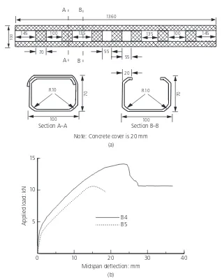
After taking into account the results of the previous three beams, a beam reinforced with a lipped CFRP U-channel with intermittent closed loops and an aggregate coating on all internal and external surfaces was designed and tested (beam B4) as a means to achieve stronger and stiffer beams with improved post-breakage strength and ductility. In order to demonstrate the applicability of the earlier research findings to beams with different design parameters, the dimensions and the concrete strength (25 MPa) of the new beam (B4) were chosen to be different to those of the previous three beams. The cross-section of the aggregate-coated CFRP channel used in B4 was 100 mm70 mm and it had lips 20 mm wide and intermittent closed loops (Figure 9(a)). The size of the lips and the spacing of the tabs were chosen to provide sufficient space for the application of aggregate coating and concrete casting. Fabrication of the CFRP channel and aggregate coating were done in the same way as for B2 and B3. The overall dimensions of the concrete beam were 1370 mm150 mm100 mm. For comparison of the results, a reference beam (B5) of the same dimensions as B4, but with a plain CFRP U-channel, was also fabricated and tested. Beams B4 and B5 were tested in four-point bending, similarly to the previous three beams, but with shear span of 510 mm and constant moment zone of 250 mm (the clear span of the beam was 1270 mm). Strain gauges were fixed on the CFRP channel and concrete at beam midspan.
Similarly to the previous three beams, B4 and B5 demonstrated even distributions of flexural cracks within the constant moment zone and nominal numbers of minor cracks within the shear spans. Both beams failed in the same way as the three previous beams, where separation of a narrow concrete slit above the top edge of the CFRP channel at midspan was followed by buckling/bending of a narrow concrete column (Figure 8(b)). Figure 9(b) shows the load–midspan deflection relationships. As expected, beam B4 showed a higher strength (peak load 14·1 kN, which is equivalent to the design load if
5 15 25 35 45
10 20 30 40 50
B1
B3 B2
Applied load: kN (a)
(b)
Neutral axis depth: mm
Figure 8. (a) Applied load–neutral axis depth relationships of the
the beam had been reinforced with two 10 mm dia. steel bars of yield strength 500 MPa), flexural stiffness and ductility (ductility index 58·8%) compared to B5 (peak load 10·9 kN and ductility index 24·4%). Similarly to B2, B4 demonstrated greater strength and stiffness due to improved composite action between the CFRP channel and concrete. However, the drop in load after the peak load in B4 was 23·8%, compared to 49·1% in B2; this suggests the contribution of the anchorages for an improved post-breakage behaviour.
Figure 10 shows the top surface strain and CFRP strain against applied load at beam midspan. The results suggest that the compressive strain at the top surface of B5 at the peak load is 0·00188 and this value matches with that in B1 (0·001870), which had a similar reinforcement arrangement. The compressive strain at the top surface of B4 at the peak load is 0·00286; this value is significantly higher than that noted in B5, but, as expected, it is between the corresponding
values of 0·002617 and 0·002990 noted in B2 and B3, respect-ively. The midspan CFRP strains shown in Figure 10 also highlight the improved strength and ductility characteristics of 55
55
145 100 135 135 100 145
1360
100
70
B
B A
A
100
70
R10
Section A–A
100
70
R10
Section B–B 20
Note: Concrete cover is 20 mm
0 10 20 30 40
5 10 15
Midspan deflection: mm (a)
(b)
Applied load: kN
B4 B5
Figure 9. (a) Dimensions (mm) of the CFRP reinforcement channel used in beam B4. (b) Applied load–midspan deflection relationships
of the B4 and B5
–3000 –2000 –1000 0
0 5 10 15
5000 10 000 15 000 20 000 B4 – Concrete
B4 – CFRP B5 – Concrete B5 – CFRP
Strain: × 10–6
Applied load: kN
Figure 10. Applied load–strain relationships at midspan of B4
B4 compared to B5. The CFRP strains at the respective peak loads of B4 and B5 are 0·0113 and 0·00628, and those at the respective failure loads are 0·0202 and 0·098. These results suggest better utility of the CFRP reinforcement in B4 com-pared to B5. It should be noted that the reason for the appar-ently high CFRP strains in B4 and B5 compared to the three previous beams is because in B4 and B5 the CFRP strains were recorded along the longitudinal direction of the beam (i.e. 45° angle to the fibre directions), whereas in B1, B2 and B3 the strains were measured along the two fibre directions. An analysis of 2D strain behaviour of the CFRP channels is beyond the scope of current paper, and such analysis will be carried out by the authors in a future publication.
Conclusions
& The study has shown that concrete–CFRP bond influences
the strength and ductility of concrete beams reinforced with CFRP fabric reinforcement.
& It has been experimentally shown that use of an
aggregate coating on the surfaces of CFRP improved the composite action between the CFRP channel and concrete, thereby improving strength and stiffness of the beam compared to plain CFRP channel reinforcement. On the other hand, the provision of anchorage mechanisms at the top edges of the CFRP reinforcement ensured a better post-breakage resistance and ductility compared to plain U-channels.
& A U-channel with aggregate coating and an anchorage
system consisting of a lipped channel section with intermittent closed loops was found to provide an improved composite action between the CFRP and concrete and also provided satisfactory ductility before final failure.
& It was found that the final failure mode was concrete
failure in the compression zone, induced by a horizontal splitting developed just above the top edge of the CFRP channel, causing a narrow sliver of concrete to bend/buckle outwards. However, as a small number of test specimens of dimensions smaller than real-life beams were tested in the present study, a more generic validation of the results may be required. Challenges such as fabrication and connecting CFRP channels in long, real-life beams should also be addressed in detail.
& It is anticipated that the basis provided by the present
work could be effectively used in other applications, such as non-prismatic geometries and permanent formwork/reinforcement in thin, concrete structural members, where the flexible characteristics of dry CFRP fabrics during preparation of CFRP reinforcement may be most useful.
Supplementary data associated with this paper are openly available from the University of Southampton repository (University of Southampton Institutional Repository, 2017).
Acknowledgements
Funding from the Institution of Civil Engineers (ICE) Research and Development Enabling Trust Award 2014 and the PhD sponsorship received by the second author from Directorate General of Higher Education, Indonesia (DIKTI) are gratefully acknowledged.
REFERENCES
Achillides Z and Pilakoutas K(2004) Bond behavior of fiber reinforced polymer bars under direct pullout conditions.Journal of Composites for Construction8(2): 173–181.
Achintha M(2009)Fracture Analysis of Debonding Mechanism for FRP Plates. PhD thesis, University of Cambridge, Cambridge, UK. Achintha M(2016)Environmental Impact and Embodied Energy.
Composites UK, Hemel Hempstead, UK. See http://compositesuk. co.uk/composite-materials/applications/construction/technical-sheets (accessed 12/12/2016).
Achintha M and Burgoyne C(2012) Prediction of FRP debonding using the global-energy-balance approach.Magazine of Concrete Research64(11): 1033–1044, http://dx.doi.org/10.1680/macr. 11.00182.
Achintha M, Alami F and Bloodworth A(2015) An CFRP fabrics as internal reinforcement in concrete beams. InProceedings of the 7th Conference on Advanced Composites in Construction(Lees J (ed.)). NetComposites Ltd, Chesterfield, UK, pp. 34–40. ACI (American Concrete Institute)(2015) ACI 440.1R-15: Guide for the
design and construction of structural concrete reinforced with fiber-reinforced polymer bars. ACI, Farmington Hills, MI, USA. Aiello MA, Leone M and Pecce M(2007) Bond performances of FRP
rebars-reinforced concrete.Journal of Materials in Civil Engineering19(3): 205–213.
Ashtiani MS, Dhakal RP, Scott AN and Bull DK(2013) Cyclic beam bending test for assessment of bond-slip behavior.Engineering Structures
56: 1684–1697, https://doi.org/10.1016/j.engstruct.2013.08.005. Baena M, Torres L, Turon A and Barris C(2009) Experimental study of
bond behaviour between concrete and FRP bars using pull-out tests.Composites Part B: Engineering40(8): 784–797. Bank LC(2006)Composites for Construction: Structural Design with
FRP Materials. John Wiley & Sons, Hoboken, NJ, USA. Bank LC, Oliva MG, Bae HU, Barker JW and Yoo SW(2007) Pultruded
FRP plank as formwork and reinforcement for concrete members. Advances in Structural Engineering10(5): 525–535.
BRE (Building Research Establishment)(1997)Design of Normal Concrete Mixes, 2nd edn. BRE, Watford, UK.
Brückner A, Ortlepp R and Curbach M(2006) Textile reinforced concrete for strengthening in bending and shear.Materials and Structures
39(8): 741–748.
BSI(1990) BS 1377-2:1990: Methods of test for soils for civil engineering purposes. BSI, London, UK.
BSI(2013) BS 206:2013: Concrete–specification, performance, production and conformity. BSI, London, UK.
CEN (European Committee for Standardisation)(2004) Eurocode 2: Design of concrete structures. CEN, Brussels, Belgium. Cho J, Cho K, Park SY, Kim ST and Kim B(2010) Bond characteristics of
coarse sand coated interface between stay-in-place fibre-reinforced polymer formwork and concrete based on shear and tension tests. Canadian Journal of Civil Engineering37(5): 706–718.
Cosenza E, Manfredi G and Realfonzo R(1997) Behavior and modeling of bond of FRP rebars to concrete.Journal of Composites for Construction1(2): 40–51.
fib (The International Federation for Structural Concrete)(2007)Bulletin No. 40: FRP Reinforcement in RC Structures. The International Federation for Structural Concrete, Lausanne, Switzerland. Grelle SV and Sneed LH(2013) Review of anchorage systems for
externally bonded FRP laminates.International Journal of Concrete Structures and Materials7(1): 17–33.
Gudonis E, Timinskas E, Gribniak Vet al.(2013) FRP reinforcement for concrete structures: state-of-the-art review of application and design.Engineering Structures and Technologies5(4): 147–158.
Hawkins W, Orr J, Ibell J and Shepherd P(2017) Developing an innovative lightweight concrete flooring system for sustainable buildings.Proceedings of IABSE Conference–Creativity and
Collaboration, Bath, UK. University of Bath, Bath, UK, vol. 108, pp. 45–46.
Hsu TTC, Slate FO, Sturman GM and Winter G(1963) Microcracking of plain concrete and shape of the stress–strain curve.ACI Journal
60(14): 209–224.
Larralde J and Silva-Rodriguez R(1993) Bond and slip of FRP rebars in concrete.Journal of Materials in Civil Engineering5(1): 30–40.
Li M, Liu Y, Liu M and Wang F(2014) Research on a novel technology of FRP bonded to concrete substrate without adhesive. InProceedings of Construction Materials and Structures (Ekolu SE, Dundu M and Gao X (eds)). IOS Press, Amsterdam, the Netherlands, pp. 347–353.
Manalo A, Benmokrane B, Park K and Lutze D(2014) Recent developments on FRP bars as internal reinforcement in concrete structures.Concrete in Australia40(2): 46–56.
Orr JJ(2012)Flexible Formwork for Concrete Structures. PhD thesis, University of Bath, Bath, UK.
Punurai W, Hsu CT, Punurai S and Chen J(2013) Biaxially loaded RC slender columns strengthened by CFRP composite fabrics. Engineering Structures46: 311–321, https://doi.org/10.1016/ j.engstruct.2012.07.014.
Qin R, Zhou A and Lau D(2017) Effect of reinforcement ratio on the flexural performance of hybrid FRP reinforced concrete beams. Composites Part B: Engineering108: 200–209, https://doi.org/10. 1016/j.compositesb.2016.09.054.
Robert M and Benmokrane B(2013) Combined effects of saline solution and moist concrete on long-term durability of GFRP reinforcing bars.Construction and Building Materials38: 274–284, https://doi.org/10.1016/j.conbuildmat.2012.08.021. Shams A, Horstmannb M and Heggera J(2014) Experimental
investigations on textile-reinforced concrete (TRC) sandwich sections.Composite Structures118: 643–653, https://doi.org/10. 1016/j.compstruct.2014.07.056.
University of Southampton Institutional Repository(2017) http://doi. org/10.5258/SOTON/D140 (accessed 01/12/2017).
Wang F, Li M and Hu S(2014) Bond behavior of roughing FRP sheet bonded to concrete substrate.Construction and Building Materials
73: 145–152, https://doi.org/10.1016/j.conbuildmat.2014.09.057.