J. Mater. Environ. Sci., 2018, Volume 9, Issue 8, Page 2328-2333
Lilis Hermida
1*, Ahmad Zuhairi Abdullah
2, Abdul Rahman Mohamed
21 Department of Chemical Engineering, Engineering Faculty, Universitas Lampung,
Bandar Lampung 35145, Indonesia
2 School of Chemical Engineering, Universiti Sains Malaysia, 14300 Nibong Tebal, Penang, Malaysia
1. Introduction
Catalysis is a process that increase in the rate of a chemical reaction due to the contribution of an additional material called a catalyst [1]. The catalystaccelerates a chemical reaction process without being consumed in the process There are two main types of catalysts–homogeneousandheterogeneous. Homogeneous catalysts are present in the same phaseas reactants and products, usually liquid. Heterogeneous catalysts are present in a different phase, usually solid. Liquid catalystssuch as HF, H2SO4, HClO4 and H3PO4 are commonly applied for
most chemical reactions in industries including petrochemicals, oil refining and chemicals. Since 1940 those liquid catalysts have tended to be replaced by solid catalystsbecause they have more advantages in terms of catalyst regeneration, decreasing corrosion problem, and environmentally safe disposal [2]. Fe, Ni, Pd, Pt are examples of solid catalysts.One or more kinds of catalysts can be loaded on another material, for example silica, which serves as a support to form a supported catalyst as a whole system[3]. The aims of using the support are to increase the dispersion of the active phases, to have a better control of the porous structure, to improve mechanical strength, to prevent sintering and to assist catalysis.
Silica-supported nickel catalysts are solid catalysts which are applied in reactions such as hydrogenation, deoxygenation, methanation, reforming, and hydrocracking [2,4]. In order to achieve high catalytic activity, silica supported nickel catalysts that had high dispersion of small nickel particles, high pore size and high stability are always desirable for those reactions [5-7]. Dispersion of nickel, pore size and stability of a catalyst are influenced by the nature of support [8-9]. Mesostructured cellular foam (MCF) silica is a mesoporous silica material that has ultra-large pore sizes (up to 500 Å) and hydrothermally robust material [10-13]. These properties make MCF silica appropriate to be used as support since they allow favourable conditions for incorporation of active site in pore of the MCF silica. In our previous study, incorporation of nickel in MCF silica was successfully carried out to produce MCF silica-supported nickel catalyst [14]. Dispersion of nickel and porosity of the catalyst were investigated using nitrogen adsorption-desorption, transmission electron microscopy (TEM), X-ray diffraction (XRD), scanning electron microscopy (SEM) and energy dispersive X-ray (EDX) analyses [14]. It was found that the MCF silica-supported nickel catalyst obtained achieved nickel content of 17.57 wt% with nanoparticle sizes (1 - 2 nm) and the catalyst had pore size
Abstract
In the present study, active site–support bonds in calcined and reduced catalysts of MCF silica-supported nickel catalysts were investigated using FTIR analyses. FTIR results show the presence of nickel phyllosilicate bonds (-O-Ni-O-Si) in the calcined catalysts.However, nickel phyllosilicate bonds were not detected in the reduced catalysts indicating that nickel phyllosilicate bons were absence after reduction process. FTIR results confirmed the presence of Ni-O-Si bond in the reduced catalysts. TGA analyses were also carried to investigate catalyst stability in terms of weight loss, thermal behaviour and structural destruction. According to the TGA results, dried catalyst of MCF silica-supported nickel catalyst showed weight loss of around 9% in a region from room temperature to 300 oC and weigh loss of 6% at above 300 oC. Weight loss from room temperature to 300 oC was ascribed to desorption of physisorbed and chemisorbed water. Meanwhile, weight loss at above 300 oC could be due to slow decompositions of nickel phyllosilicate to the formation of nickel oxide.
of 90 Å. However, investigation of interactions between active site with support (active site–support bond) in the MCF silica-supported nickel catalyst has not been reported yet. The presence of bond between active site and support is required to create efficient and effective catalyst.
Fourier Transform Infrared (FT-IR) is a powerful technique for identifying types of chemical bonds in a molecule [15]. Additionally, Thermogravimetric analysis (TGA) has been used extensively for measurement of thermal stability of materials [16]. Therefore, in the present study FT-IR analysis was carried out to observe and evaluate the presence of active site–support bonds in calcined and reduced catalysts of MCF silica-supported nickel catalysts. Besides that, TGA analysis was also conducted to investigate catalyst stability in terms of weight loss, thermal behaviour and structural destruction. Catalyst stabilityisanimportant property of all solid catalysts since most of the industrial chemical transformations to prepare a product are conducted at medium to high temperatures and pressures.
2. Experimental work
2.1 MCF support preparationMCF silica materials with different structures were synthesized according to procedure as previously reported [14]. In a typical synthesis, 4 g of Pluronics 123 was dissolved in 70 ml of 1.6 M HCl. Then, 6.8 ml of trimethylbenzene (TMB) was added, and the resulting solution was heated to 40°C with rapid stirring to synthesize the microemulsion (template). After stirring for 2 h, 9.2 ml of tetraethyl orthosilicate (TEOS) was added to the solution and stirred for 5 min. Then, the solution was transferred to a polyethylene bottle and kept at 40°C in an oven for 20 h for the formation of pre-condensed silica foam. After that, the mixture was removed from the oven and then NH4F·HF solution (92 mg in 10 ml DI water) was added to the mixture under slow
mixing. Then, the mixture was aged at 80°C in an oven with aging time of 2 days. After cooling at room temperature, the mixture was filtered and the collected solid was then dried at 100°C for 12 h. Then, calcination was carried out in static air at 300°C for 0.5 h and 500°C for 6 h to obtain MCF(9.2T-2D) silica. The same procedure was also applied to prepare MCF(9.2T-3D) silica except the use of aging time period. MCF(9.2T-3D) silica was prepared by using aging time of 3 days.
2.2. Incorporations of Ni into MCF silica to produce MCF-silica supported nickel catalysts
The MCF silica supports were functionalized with nickel using a procedure adopted in the literature [15]. In the procedure, 0.3 ml of HNO3 69 % wt/wt was added to 10.156 g of Ni(NO3)2.6H2O and then mixed with
deionized water (DI) until 250 ml to obtain aqueous solution. 40 ml of the aqueous solution was utilized to dissolve 6.3 g of urea to obtain urea solution and 210 ml of the aqueous solution was added to 1.9 g of the MCF obtain a suspension. The suspension was heated at 40 oC, and then mixed with the urea solution under rapid mixing. After that, the mixture was heated to 90 oC for 2 h under static condition. After cooling, the mixture was filtered and the solid was washed with 20 ml of hot distilled water (~50 oC) followed by drying at 100 oC for 12 h. The dried samples are designated NiMCF (9.2T-aD) in which a is duration of aging time in the synthesis of MCF supports. Then, the solids were calcined in static air at 300 oC for 6 h. the calcined sample are designated NiMCF (9.2T-aD)(C). Finally, the calcined samples were reduced at 550 oC for 2.5 h under hydrogen stream, and then cooled to room temperature under nitrogen flow to obtain MCF-silica supported nickel catalysts. The reduced catalysts are designated NiMCF(9.2T-aD)(R). Preparations of the MCF silica supports and MCF silica-supported nickel catalysts can be summarized as in Table 1.
Table 1 VariousMCF silica supports and MCF silica-supported nickel catalysts
No Supports Dried catalyst Calcined catalyst Reduced catalyst
1 MCF(9.2T-2D) NiMCF(9.2T-2D) NiMCF(9.2T-2D)(C) NiMCF(9.2T-2D)(R)
2 MCF(9.2T-3D) NiMCF(9.2T-3D) NiMCF(9.2T-3D)(C) NiMCF(9.2T-3D)(R)
2.3. Characterization
The TGA was carried out to observe the change in weight of the catalyst sample as it was heated in a temperature range from 31 to 840 oC. The thermal gravimetric analyzer unit coupled with a TG controller (TAC 7/DX) was supplied by Perkin-Elmer, USA. About 5 mg of catalyst sample was heated with a heating rate of 10oC/min and an air flow rate of 25 ml/min. The resulted TG curves indicated weight loss of the sample with increasing temperature.
3. Results and discussion
Figure 1 shows FTIR spectra that were collected for MCF(9.2T-3D) silica and calcined catalysts, i.e. NiMCF(9.2T-2D)(C) and NiMCF(9.2T-3D)(C). The spectra were obtained in a frequency range of 2000-500 cm-1. In this range, variation of the absorption profiles that characterized Ni-O-Si interactions can be observed [18-20]. The FTIR spectrum of the unsupported MCF silica (MCF(9.2T-3D) exhibited characteristic peak and shoulder at approximately 1086 and 1200 cm-1 that were assigned to stretching vibrations of the three- dimensional Si-O-Si network [21]. The stretching vibration of the Si-O-Si network was also observed through a weaker peak at 798 cm-1[22-25]. Other researchers observed characteristic Si-O-Si vibrations at 460 cm-1[22, 26].According to literature vibrations at about 550 cm-1 were attributed to Si-O bonds [27]
Figure 1: FTIR spectra of unsupported MCF(9.2T-3D) silica dan some calcined catalysts, i.e. NiMCF(9.2T-2D)(C) and NiMCF(9.2T-3D)(C)
Furthermore, compared to the unsupported MCF(9.2T-3D) silica material, FT-IR spectra of the calcined catalysts of NiMCF(9.2T-2D)(C) and NiMCF(9.2T-3D)(C) demonstrated lower intensities of the silica Si-O-Si stretching vibration bands at 798, 1086 and 1200 cm-1, as can be seen in the Figure 1. However, a new band at 660 cm-1 appears in the FT-IR spectra of the calcined catalysts. The band at 660 cm-1 is attributed to the presence of nickel phyllosilicate bonds which covered the surface in the calcined catalysts [28-29]. Formation of nickel phyllosilicate bonds in the calcined catalysts is shown in Figure 2.
The generation of the nickel phyllosilicate bonds seems to be more significant in NiMCF (9.2T-2D)(C) than those in NiMCF(9.2T-3D)(C). This could indicate the larger sizes of the nickel phyllosilicate bonds in the NiMCF (9.2T-2D)(C).
Figure 3 shows FTIR spectra that were collected for the calcined catalysts i.e. NiMCF(9.2T-2D)(C) and NiMCF(9.2T-3D)(C) as well as for the reduced catalysts i.e. NiMCF(9.2T-2D)(R) and NiMCF(9.2T-3D)(R). As can be noted from the Figure 3, when compared to the FTIR spectra of the calcined catalysts, the FTIR spectra of the reduced catalysts demonstrate reappearance of higher intensities of the silicate vibrations (bearing the supports) that are especially indicated by the band at 1086 cm-1. Meanwhile, the presence of the band at 660 cm-1 is not detected in FTIR spectra of the reduced catalysts. The result indicated that nickel phyllosilicate bonds were absence after reduction process. The nickel phyllosilicate could change into metallic nickel on the surface of the reduced samples. This also provides indirect information on the strength of Ni-O-Si interaction in the reduced catalysts. The result was in agreement with a report in the literature in which silica gel was incorporated with metallic nickel [20].
Figure 3: FTIR spectra of calcined catalysts i.e. NiMCF(9.2T-2D)(C) and NiMCF(9.2T-3D)(C) and the reduced catalysts i.e. NiMCF(9.2T-2D)(R) and NiMCF(9.2T-3D)(R)
!
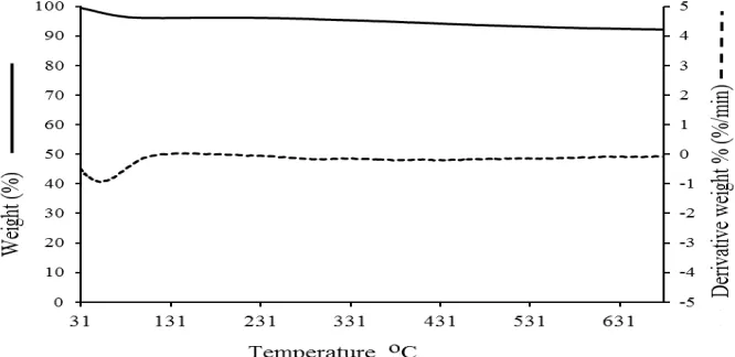
Weight loss, thermal behaviour and structural destruction of MCF silica and nickel functionalized MCF catalyst were investigated by means of TGA. Figure 4shows a TGA thermogram of MCF silica. In order to obtain better visualization of weight changes, the first derivative of the weight changes from the TGA test is also presented in the Figure 4. Result obtained from the TGA thermogram shows a desorption region that occurred from room temperature to 110 oC. The derivative of the thermogram clearly reveals this inflection point with a peak located at 54 oC. The weight loss of the MCF silica in this region was only attributed to desorption of physically adsorbed water.
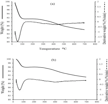
TGA thermogram of a corresponding dried catalyst sample was carried with the aim of establishing the most appropriate temperature to calcine the dried catalyst sample before reduction process to produce NiMCF(9.2T-3D)(R) catalyst. TGA thermogram as well as its derivative of NiMCF(9.2T-3D) dried catalyst is shown in Figure 5(a). The TGA thermogram in the figure shows a region from room temperature to 110 oC with weight loss of about 8% and a region from 200 to 300 with weight loss of below 1%.
!
! !
Figure 5: TGA thermograms of (a): dried NiMCF(9.2T-3D) catalyst and (b) : NiMCF(9.2T-3D(C) catalyst! !
At temperatures above 300, around 6% weight loss was observed. The regions from room temperature to 300 oC were ascribed to desorption of physisorbed and chemisorbed water as reported in the literature [30]. Meanwhile, weight loss of the catalyst sample above 300 oC could be due to slow decompositions of nickelphyllosilicate in the catalyst sample leading to the formation of nickel oxide. Hence, calcinations process of the dried sample above 300 oC would generate nickel oxide that was evenly dispersed in the catalyst. Metal oxide dispersed in calcined catalyst could generate coarse or large metal particles after reduction process as reported in the literatures [31-32]. It is desirable to generate nickel particles with small sizes that are distributed in nickel functionalized MCF catalyst to obtain high catalytic activity. Therefore, in order to avoid the formation of nickel oxide, calcinations process of the dried sample was appropriate to be carried out at 300 oC. Figure 5(b)shows the TGA thermogram of a calcined catalyst, NiMCF(9.2T-3D)(C), i.e. the dried catalyst sample that had been calcined at 300 oC for 6 hours. As can be seen from the figure, the TGA thermogram of calcined catalyst was almost the same as that of the dried catalyst except the region of weight losses due to desorption of water that was smaller than that in the dried catalyst. The results suggested that the calcination process at 300 oC led to more elimination of water. The more elimination of water before reduction process could produce catalyst with smaller sizes of metal particles [30].
!
Conclusion
NiMCF(9.2T-2D)(C) could be was larger than that in NiMCF(9.2T-3D)(C). FT-IR analysis results of reduced catalysts i.e. NiMCF(9.2T-2D)(R) and NiMCF(9.2T-3D) (R) showed nonappearances of nickel phyllosilicate, providing indirect information of the presence of Ni-O-Si bonds in the reduced catalysts. Furthermore, TGA of NiMCF(9.2T-3D)(C) calcined catalyst was almost the same as that of NiMCF(9.2T-3D) dried catalyst except the region of weight losses due to desorption of water. This indicated that calcination process carried out at 300
oC led to more elimination of water. More elimination of water before reduction process could produce MCF
silica-supported nickel catalyst with smaller sizes of nickel particles.
Acknowledgements-
Research University grant (no. 814181) from Universiti Sains Malaysia and a Science fund grant (no. 6013381) from Ministry of Science, Technology and Innovation (MOSTI) to support this research work are gratefully acknowledged. Lilis Hermida also thanks the Directorate General of Higher Education (DIKTI), Ministry of National Education of Indonesia for her PhD scholarship.!
References
1.!Chorkendorff I, Niemantsverdriet J. W. , Concepts of Modern Catalysis and Kinetics, 2003 WILEY-VCH Verlag GmbH & Co. KGaA, Weinheim
2.!Corma A., Garcia H., Catal.Today. 38 (1997) 257-308
3.!Jong K.P D.. Curr. Opin. Solid State Mater. Sci..4 (1)(1999)55–62.
4.!Setiabudi H.D., Lim K.H., Ainirazali N., Chin S.Y., Kamarudin N.H.N.,J. Mater. Environ. Sci. 8 (2) (2017) 573-581.
5.! Maschmeyer T., Curr Opin Solid StateMater Sci. 3- 19(1998) 71-78.
6.! Lancaster T. M., Lee S. S., Ying J. Y., Chem. Commun. 28(2005)3577-3577. 7.!Taylor W. F., Yates D. J. C., Sinfelt J. H., J. Phys. Chem. 68- 10(1964)2962-2966. 8.!Ryoo R., Jun S., J. Phys. Chem.B, 101- 3(1997) 317-320.
9.!Inagaki S., Sakamoto Y., Fukushima Y., Terasaki O., Chem. Mater. 8- 89(1996) 2089-2095.
10.! Schmidt-Winkel P., Lukens Jr. W.W., Zhao D., Yang P., Chmelka B.F., Stucky, G.D., J. Am. Chem. Soc. 14.! Hermida L., Abdullah A.Z., Mohamed A.R.,Mater Sci Appl., 4(2013)52-62.
15.! Santos C., Fraga M.E., Kozakiewicz Z., Lima N., Research in Microbiology 161 (2010) 168-175 16.!!Jain S, Sharma M.P..Fuel,( 2012), Pages 252-257
17.! Nares R., Ramirez J., Gutierrez-Alejandre A., Cuevas R., Ind. Eng. Chem. Res., 48- 3(2009) 1154-1162. 18.! Parler C. M., Ritter J. A., Amiridis M. D., .Cryst-J. NonSolids, 279(2001)119-125.
19.! Kermarec M., Carriat J. Y., Burattin P., Che M., J. Phys. Chem., 98(1994)12008-12017.
20.! Gabrovska M., Krstib J., Tzvetkov P., Tenchev K., Shopska M., Vukeli N., Jovanovic D., Russ. J. Phys. Chem. A.,85-13(2011)2392-2398.
21.! Perry C .C, X.Li, D N Waters, Spectrochimica Acta, Part A 47A (1991) 1487-1494. 22.! Wood D.L., Rabinovich E.M., J. Non-Cryst. Solids,. 107 (1989) 199-211.
23.! Yamane M., Sol-Gel Technology for Thin Films. New Jersey, Noyes Publications Park Ridge (1989) 200. 24.! Cordoba G., Arroyo R., Fierro J.L.G., Viniegra M., J. Solid State Chem., 123 (1996) 93-99.
25.! Sheng T.C., Lang S., Morrow B.A., Gay I.D. J.Catal. 148 (1994) 341-347.
26.! Almeida R.M., Guiton T.A., Pantano C.G. J. Non-Cryst. Solids. 121 (1990) 193-197. 27.! Che C., Glotch T.D., Bish D.L., Michalski J.R., Xu W., J. Geophys. Res., 116 (2011)1-23 28.! Ghuge K., A. Bhat, Babu. G. Appl. Catal. A, 103 (1993) 183-204.
29.! Sohn J. Catal. Today, 73 (2002) 197-209.
30.! Burattin P., Che M., Louis C. J. Phys. Chem.B, 103(30) (1999) 6171-6178.
31.! Sietsma J.R.A., Meeldijk J.D., Versluijs-Helder M.V., Broesma A. ,van Dillen A.J.,de Jongh P.E., de Jong K.P. Chem. Mater. 20 (2008) 2921-2931.
32.! Banerjee R., Crozier P.A. J. Phys. Chem.C. 116 (2012) 11486-11495.