MT 08
Nonlinear Behaviour of Toroidal Shells of In-Plane and Out-of-Plane Oval
Cross Sections under Internal Pressure
Asnawi Lubis*)
Jurusan Teknik Mesin, Fakultas Teknik, Universitas Lampung
Jalan Professor Soemantri Brojonegoro No.1 Bandar Lampung 35145 Indonesia
*)
E-mail: [email protected]
Abstract
Toroidal shells as pressure vessel have been used as LPG storage tanks for passenger cars. Current practice places the toroidal LPG tank on the position of spare wheel of a passenger car. In addition to its easy in installation on a car, toroidal tanks have higher limit pressure than an equivalent cylindrical tanks for certain values of radius ratio. In practice, designer has to decide whether choosing circular or oval cross-section. Oval cross-section can be chosen either in-plane or plane oval. In-plane oval cross section has major axis from extrados to intrados, whereas, out-of-plane oval has major axis of cross-section from crown to crown. This paper reports a finite element study of the nonlinear behaviour of in-plane and out-of-plane oval toroidal shell under internal pressure. The ANSYS shell element has been used in finite element modeling. The material properties were assumed to be elastic-perfectly plastic. Limit pressure was obtained via the well-known Newton-Raphson algorithm for nonlinear analysis. Radial displacement of nodes in the position of extrados, 450 from extrados, crown, 1350 from extrados, and intrados were reviewed. The results show that the load – displacement relation is linear for toroidal circular both in elastic and plastic state indicated the membrane dominant behavior. Very significant nonlinearity occurs for both in-plane and out-of-plane oval cross-section, believe to be due to shell bending. The overall results show that toroidal shells of circular cross-section have higher limit pressure than those of oval cross-section. Volume expansion of toroidal shell of circular cross-section due to internal pressure dominated by membrane behavior, while for oval cross-section, bending behavior contributes. It is interesting to note that limit pressure of toroidal shell having out-of-plane oval cross-section is higher than those of in-plane oval.
Keywords: toroidal shells, in-plane oval, out-of-plane oval, nonlinerity, membrane, shell bending, finite element
Introduction
Toroidal shells are usually used as pressure vessels and pipe bend (elbows) in piping systems. In pressure vessels application,
complete toroidal shell can be used as storage tank for LPG in a passenger cars. This technology has been applied in many european countries. Incomplete toroidal shells
are usually used elbows and pipe bend to absorb thermal exspansion.
The behaviour of pipe bends and elbows has attracted the researchers long time
MT 08
phenomenon has been acomodated in the ASME piping code since then in terms of pressure reduction effect for flexibility and stress-intenfication factors [3]. These factors were assumed to be applied for both in-plane cosing and opening bending. Lubis and Boyle [4] derived equations for the pressure reduction effect in line with the ASME code equations, originally proposed by Rodabaugh dan George [5]. The nonlinear behaviour of piping elbows under in-plane bending and internal pressure was reported by Lubis [6]. This paper shows that nonlinearity occurs more significant in piping elbows loaded by in-plane closing bending and internal pressure than those loaded by in-plane opening bending and internal pressure. It was worth noting that in-plane closing bending cause the cross-section become oval with major axis from crown to crown, known as out-of-plane oval. Subsequent internal pressure loading would reduce ovality and open-up the bend. In contra to this, in-plane opening bending cause ovalisation of cross section with major axis from extrados to intrados, known as in-plane oval. Subsequent internal pressure loading would also reduce ovality but close-up the bend. This results shows that nonlinearity more significant for pipe elbows having out-of-plane oval cross-section.
Research on the behaviour of complete toroidal shells as pressure vessels is quite a few found in literatures compared to incomplete toroidal shells as pipe bends and elbows. This is probably caused by limitation of its usage and difficulty in fabrication compared to cylindrical pressure vessel. Nowadays, toroidal shells are used as LPG storage tanks for passengers cars, particularly in some european countries [7]. Analysis of stress and strain of LPG toroidal tanks using finite element methods has been reported by Velickovic [8]. Strength analisis of circular toroidal tank for LPG 3kg proposed using in Indonesian household has been reported by Lubis [9]. His analysis shows that the strength of a toroidal tank could be three times the strength of an equivalen cylindrical tank [10]. The influence of ovality and ellipticity on the strength and volume expansion of toroidal tank has been analysed
by Akmal et al [11] and Lubis et al [12]. Both papers shows that circular cross section toroidal tank have higher limit pressure than elliptic of oval cross section toroidal tanks. However, for certain reason, such as stability and available space in a car, oval or elliptic cross section toroidal tank must be chosen and their behavior under internal pressure load must be accounted. This paper aims to report the results of a finite element study of the nonlinear behavior of in-plane and out-of-plane oval cross section toroidal shells under internal pressure loading.
Literaure Review
Membrane Theory. A complete toroidal shell (tank) can be considered as a curved cylinder without end. Compared to an equivalen cylinder, a toroidal shell need less material because no need to close its ends. For special case where a toroidal shell can be obtained by rotating a circle of radius a about a vertical axis with distance b from the centre of the circle (Figure 1), point A is a point on parallel circle of radius:
sin
0 b a
r (1)
Fig.1 Section view of a circular toroidal shell [13]
If internal pressure, p, is the only load work on the shell, then from equilibrium of forces in the hoop direction (arc AB in Figure 1) the following equation is obtained:
2 2
0 0 sin2rN pr b (2)
MT 08 equation apply [13]:
Z
By substituting eq. (3) into (4), the following equation is obtained:
stress on shell element are:
If is measured from extrados (position 12) toward crown (position 9) and then toward intrados (position 6) on a clock, eq.(8) can be further written as:
Equation (6b) shows that longitudinal stress on a toroidal shell due to internal pressure is
not depend on radius ratio , and circumferential position . This equation equals to longitudinal stress on a closed ends cylindrical shell. On the other hand, hoop posisi circumferensial .
Ovality of Cross Section. The behavior of cylindrical shell having oval cross section has been reported by Haigh in 1936 [2]. Mean radius r1 of the cross section of cylindrical
shell having oval cross section is expressed as nominal radius plus a cosinus of an angle as
Fig.2 Notation for Haigh’s analysis [14]
When internal pressure act on, the ovality of cross section would reduce (tend to be circular) with a new value of radius, assumed by Haigh as:
MT 08 theory of Castigliano for strain energy due to bending. They compared the bending stress that occurs in shell wall obtained using the Haigh’s equation, theorema of Castigliano, and finite element methods for the following case: (1) straight pipe of elliptic cross section, (2) straight pipe of variour wall thickness, and (3) circular cross section toroidal shell They have not analyze the bending stress for toroidal shell of oval cross section, the subject focus of this paper.
Finite Element Analysis
The results presented in this paper were obtained using finite element method with ANSYS 13. The toroidal model considered is typical to be used as gas fuel tank for
passenger cars, based on tank’s volume of 45 liters water. Volume of a circular toroidal tank (Fig.1) is calculated from the equation:
b can be calculated from:
3 2.5, 3, dan 4, the chosen values in this paper, the corresponding cross section radius are chosen in this paper, because according to the previous research by Akmal et al [11], ovality beyond this value causes the limit pressure drop below the pressure to yield. Ovality was defined as [15]: material of the LPG 3kg storage tank used in Indonesian household, i.e., steel plats produced by PT Krakatau Steel with detail specification: JIS G3116 SG-295, thickness of 2.3mm. The material properties needed in this analysis are Young’s modulus E, yield joint is assumed to be perfect (joint efficiency is unity). Another assumption is that the shell’s walls thickness is uniform.
The element type used is the ANSYS
MT 08
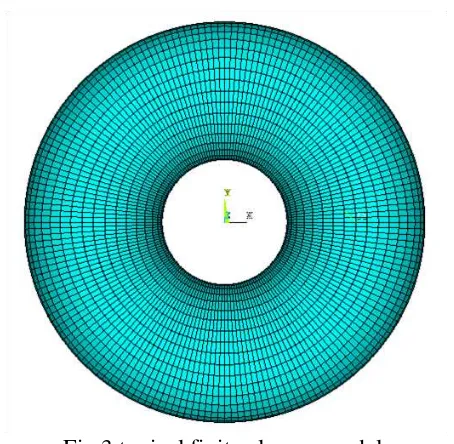
Fig.3 typical finite elemen model
The advantage of symmetry was taken into account, so that only half of the geometry was modeled. Additional boundary condition is zero displacement in the longitudinal direction for all nodes in a plane cross section. Iinternal pressure loading to be applied to get the limit pressure can be estimated by calculating the pressure to yield, py. Pressure
to yield py can be calculated from eq. (9) for
intrados as follows:
1 2
1 2
r t
py y (17)
For radius rasio ρ = 2.5, 3, dan 4, and meterial properties of JIS G3116 SG-295 (σY = 295
MPa), corresponding pressure to yield is 5.248 MPa, 5.984 MPa, dan 7.014 MPa respectively. These pressure are pressure needed to cause plasticity initiates. Limit pressure would be beyond these values, but for the purpose of this analysis, internal pressure load of 1.5py was applied. To get
limit pressure pL, the load was applied as
ramped. The well-known Newton-Raphson algorithm for nonlinear analysis was implemented.
Results and Discussion
Nonlinear behavior of complete toroidal shell (toroidal pressure vessel) was obtained for radial displacement of nodes in the following circumferential (angle) position from extrados
toward intraos: 00, 450, 900, 1350, and 1800. The position of 00 is called extrados, 900 is crown, and 1800 is intrados.
Figure 4 shows the radial displacement of nodes of circular toroidal shell for radius ratio of 2.5. It can be seen that the load-displacement relation is linear in elastic and plastic region (bilinear), indicated the membrane dominated behavior. This figure also shows that radial displacement of extrados and intrados nodes are negative, but crown nodes are positif. It can be seen also from this figure that volume expansion occurs due to membrane dominated behavior.
Figure 4 load displacement relation for ρ = 2.5 and Ω = 0.0
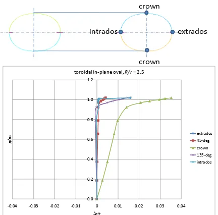
Figure 5 shows the load-displacement relation of nodes for radius ratio of 2.5 and in-plane oval cross-section, Ω = 0.2. This figure shows significant nonlinearity. It can also be seen that nodes at the crown position undergo highest radial displacement. Significant volume expansion is shown by positive radial displacement in this figure.
extrados intrados
crown
crown
0.0 0.2 0.4 0.6 0.8 1.0 1.2
-0.0025 -0.0020 -0.0015 -0.0010 -0.0005 0.0000 0.0005 0.0010 0.0015 0.0020 0.0025
p/
py
Δr/r
toroidal circular, R/r= 2.5
extrados
45-deg
crown
135-deg
MT 08
Figure 5 load displacement relation for ρ = 2.5 and Ω = 0.2
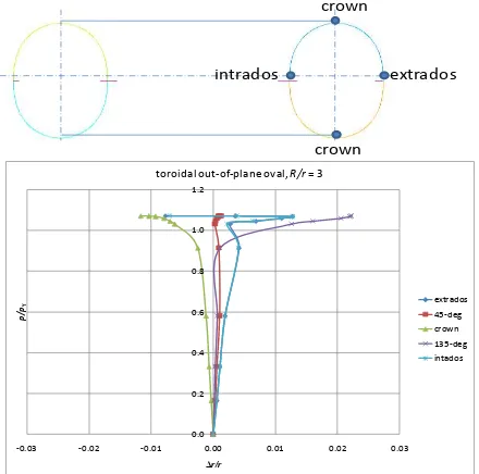
Figure 6 shows load-displacement relation for radius ratio of 2.5 and out-of-plane ovality Ω = -0.2. Again, this figure shows significant nonlinearity. As in the previous figures, nodes at crown undergo farthest radial displacement. Comparing the radial displacement from figures 4, 6, and 6, show that in-plane oval cross-section have the highest value of radial displacement followed by out-of-plane oval, and circular. On the other hand, circular cross-section toroidal shell is the strongest against internal pressure, followed by out-of-plane oval and in-out-of-plane oval.
Fig.6 load displacement relation for ρ = 2.5 and Ω = -0.2
Figure 7 shows the load-displacement relation for circular cross-section toroidal shell having radius ratio of 3.0. Again, this figure shows can be seen that significant nonlinearity occurs in radial displacement with maximum displacement occurs for crown nodes.
Fig.8 load displacement relation for ρ = 3.0 and Ω = 0.2.
Figure 9 shows the same graph for out-of-plane oval cross section having radius ratio of
extrados
toroidal in-plane oval, R/r= 2.5
extrados
-0.0200 -0.0150 -0.0100 -0.0050 0.0000 0.0050 0.0100 0.0150 0.0200
p/
pY
Δr/r
toroidal out-of-plane oval, R/r= 2.5
extrados
0.0000 0.0005 0.0010 0.0015 0.0020 0.0025
p/
pY
Δr/r
toroidal circular, R/r= 3
extrados
-0.08 -0.06 -0.04 -0.02 0.00 0.02 0.04 0.06 0.08
p/
pY
Δr/r
toroidal in-plane oval, R/r= 3
extrados 45-deg crown
MT 08
3. This figure also shows significant nonlinearity, but the maximum radial displacement occurs for nodes between crown and intrados. Nodes at crown also show significant radial displacement, but having negative values. Comparing the last three figures confirm that under internal pressure loading, circular cross-section toroidal shell is the strongest, followed by out-of-plane oval, and in-pale oval.
Fig.9 load displacement relation for ρ = 3.0 and Ω = -0.2.
Figure 10 shows the load-displacement relation for circular toroidal shell having radius ratio of 4. Again, linear behavior can be seen from this figure, where nodes at crown has the maximum radial displacement.
Fig.10 load displacement relation for ρ = 4.0 and Ω = 0.0.
Figure 11 dan 12 shows load-displacement for in-plane and out-of-plane oval cross-section respectively having radius ratio of 4. Both figures show nonlinear behavior. It is interesting to note that nodes at crown position have the highest positive value of radial displacement for in-plane oval, while the highest value of this occurs for nodes at extrados and intrados position for out-of-plane bending. The last figure also shows negative radial displacement for crown node. Comparing the last three figures, again shows that circular cross-section toroidal shell has the highest limit pressure, followed by out-of-plane oval and in-out-of-plane oval.
Fig.11 load displacement relation for ρ = 4.0
-0.03 -0.02 -0.01 0.00 0.01 0.02 0.03
p/
pY
Δr/r
toroidal out-of-plane oval, R/r= 3
extrados
-0.0025 -0.0020 -0.0015 -0.0010 -0.0005 0.00000.00050.0010 0.00150.00200.0025
p/
pY
Δr/r
toroidal circular, R/r= 4
extrados
-0.10 -0.08 -0.06 -0.04 -0.02 0.00 0.02 0.04 0.06 0.08 0.10
p/
toroidal out-of-plane oval, R/r = 4
MT 08
It is interesting to note the complete toroidal shell having out-of-plane oval cross section is stronger than those having in-plane oval cross section. Recall the behavior of incomplete toroidal shells as pipe bend and elbows, out-of-plane oval results from in-plane closing bending, while plane oval results from in-plane opening bending. Previous study by Lubis [6] shows pipe bend under closing bending stiffer than under opening bending. This is the reverse of the results shown in the present paper.
Conclusion
The study of the nonlinear behavior of toroidal shells loaded by internal pressure presented in this paper leads to the following significant conclusion:
(1) Circular cross-section toroidal shell behave linear both in elastic and plastic region, indicates membrane dominant behavior;
(2) Oval cross-section show nonlinear behavior, bending of the shell’s wall contributed to this behavior;
(3) Circular cross-section toroidal shells are the strongest, followed by out-of-plane and in-out-of-plane oval cross section.
Acknowledgement
The author would like to acknowledge the Faculty of Engineering, the University of Lampung for funding this research in DIPA FT 2015.
References
[1] von Karman, Th., 1911, Ueber die Formanderung dunnwandiger Rohre, insbesondere federnder Ausgleichrohre.
Zeitschrift des Vereines deutscher Ingenieure, Vol. 55, Part 2, pp. 1889 – 95.
[2] Haigh, B. P., 1936, An Estimate of the Stresses Induces in a Tube that is not Initially Quite Circular. Proceeding of the Institution of Mechanical Engineers, Vol. 133, pp. 96 – 98.
[3] ASME B31.1, 2014, Process Piping, ASME Code for Pressure Piping.
[4] Lubis, A., and Boyle, J.T., 2004, The Pressure Reduction Effect in Smooth Pipin Elbows – Revisited. International Journal of Pressure Vessels and Piping, Vol. 81 No.2, page 119-125.
[5] Rodabaugh, E. C., and George, H. H., 1957, Effect of Internal Pressure on Flexibility and Stress-Intensification Factors of Curved Pipes or Welding Elbows. Transactions of the ASME, Vol. 79, pp. 939 – 48.
[6] Lubis, A., 2006, Finite Element Analysis of Pressurized Piping Elbows Subjected to In-Plane Opening Bending. Jurnal Ilmiah POROS, Vol. 9 No.1, January, Universitas Tarumanagara. [7] Kisioglu, Y., 2009, Burst tests and
volume expansions of vehicle toroidal LPG fuel tanks. Turkish Journal of Engineering and Environmental Sciences, vol. 33, pp. 117 – 125.
[8] Velickovic, V., 2007, Stress and Strain States in the Material of the Stressed Toroidal Container for Liquefied Petroleum Gas. Scintific Technical Review, Vol. LVII, No. 3 – 4, pp. 94 – 105.
[9] Lubis, A., 2011, Strength design of toroidal tank for LPG 3-kg. Proceeding SNTTM-10, Universitas Brawijaya, Malang, 2 – 3 November 2011.
[10] Lubis, A., Saragih, R.S., and Suudi, A., 2010, A study of limit pressure of LPG 3kg tanks using finite element method Proceeding SNTTM-9, Universitas Sriwijaya, Palembang, 13 – 15 Oktober. [11] Akmal, J., Lubis, A., and Mahyunis, I.,
2014, The influence of cross-section ovality on the strength and volume expansion of toroidal tank under internal pressure load. Jurnal Mechanical, Vol. 5, No.2, pp. 43 – 47. [12] Lubis, A., Akmal, J., and Winata,
M.Y.A., 2014, Analysis of strength and volume expansion of toroidal tanks of elliptic cross-section under internal pressure load. Jurnal Mechanical, Vol. 5, No.2, pp. 36 – 42
MT 08
[14] Austin, A., and Swannell, J.H., 1979, Stresses in a pipe bend of oval cross-section and varying wall thickness loaded by internal pressure. International Journal of Pressure vessel and piping, vol.7, pp. 167 – 182.
[15] Boyle, J. T., and Spence, J., A Simple Analysis for Oval, Pressurised Pipe Bends under External Bending. Proceeding of the 4th International
Conference on Pressure Vessels Technology, Vol. II, pp. 201 – 07. [16] Winarto and Wahyuadi, 2008,