VALIDATING PHOTOGRAMMETRIC ORIENTATION STEPS BY THE USE OF
RELEVANT THEORETICAL MODELS.
IMPLEMENTATION IN THE “ARPENTEUR” FRAMEWORK
Amine Mahiddine a, Julien Seinturier a, Daniela Peloso a, Hakim Boulaassal a, Jean-Marc Boï a, Djamel Merad a, Pierre Drap a
a
LSIS umr CNRS 7296, Centre National de la Recherche Scientifique, Marseille, France ([email protected])
Commission V, WG V/2
KEY WORDS: Photogrammetry, Orientation, Homologous Point, Validation
ABSTRACT:
The new advance in photogrammetry using the automatic procedures such as the famous algorithm which was proposed by David Lowe(Lowe, 2004) features descriptors and matching (SIFT) and then the recent development of external orientation (Nister (Stewenius et alii, 2006) or Snavely (Snavely et alii, 2010)) have changed drastically the way of measuring space with photogrammetry. The complexity of the process and the huge quantity of processed data (thousands of photographs) makes difficult validating the different process steps.
We propose in this paper several theoretical model generation methods in order to validate the complete photogrammetric orientation process. A theoretical photogrammetric model generation has been developed in order to produce photographs, photo orientation, 3D points and 2D observations according to some defined camera and a parametric photograph distribution in the scene. In addition the use of synthesis image software generation as POV-Ray allow us to generate set of photographs with pre-computed internal and external orientation in order to check the whole pipeline from feature extraction to Photographs External Orientation.
We apply this model generation approach to several typical geometry of photogrammetric scene, stereo, parallel triplet, parallel strip and convergent models.
1. INTRODUCTION
The integration of photogrammetry, computer vision and image processing within well-known 3D reconstruction methods has enabled to make easier and quicker the generation of a 3D representation of real scenes. In particular, photogrammetry has taken advantage of image feature detection; GPU computation and parallelized computation techniques to become more automatic and to raise input data size (e.g. thousands of photographs, several million of points). The integration of all these methods within photogrammetric survey has led to an increased complexity of the whole process. It is now difficult to evaluate a step of the process without taking in account previous or next steps. We distinguish two main approaches to photogrammetric systems: conventional systems compute the orientations of photographs and the 3D points from a set of calibrated camera and 2D observations (as points on the photographs). Structure From Motion (SFM) systems produce an oriented model from a set of photographs by extracting and matching features before computing photograph orientations, camera intrinsic parameters and 3D points. A first theoretical validation of such approaches is abundant within literature, the algorithms dedicated to camera calibration, photographs orientation and to feature extraction and matching have been widely discussed. However, the evaluation and validation of these algorithms within applicative tools is more complex. Each tool provides its own optimizations like GPU computing with CUDA, OpenGL, parallelization with OpenCL, integration of heuristics for specific cases, making the study of each step of the process becomes difficult.
Instead of taking a set of photogrammetric tools and make a comprehensive evaluation, we choose to provide a framework for generating complete theoretical photogrammetric models and means for extracting the data used as input by these tools. The framework's first module provides an interface for fully parameterise the theoretical photogrammetric model to create.
The used calibrated camera intrinsic parameters such as the focal length and frame dimension in millimetres, the size in pixel of produced images, the coordinates of principal point and the lens distortion (described by Brown’s model radial and tangential parameters(Brown, 1966)) can be set. The spatial disposition of photograph stations can also be parameterized. Four predefined dispositions are available. The template of couple enables to produce a couple of oriented photographs that can be used for the validation of relative orientation processes. This template can be parameterized with the basis of the couple and the external orientation of the photographs. The template of triple is quite similar to the couple one but enables to use three photographs. The template of grid simulates a regular coverage of terrain. This configuration can be used to validate an aerial photogrammetric survey system or the coverage of an underwater site and can be parameterized with number of photographs to distribute along a grid of given size. Finally, the last template describes a repartition of the photographs along an ellipsoid. This orbital template can be parameterized by the size of its major and minor axes and the number of photographs stations at its equator and meridian. When the camera calibrations and the photograph dispositions template are chosen, the full photogrammetric model is generated by adding a pre-computed 3D point cloud. This point cloud can be a cube, a sphere or a points cloud coming from another source. With all these information, a complete photogrammetric model is generated by projecting 3D points on all photographs.
Even if theoretical models enable to evaluate conventional photogrammetry systems, they are not suitable for the evaluation of the ones based on the extraction of image features. Indeed, it not possible to generate realistic photographs (with textured objects, variable lighting, atmospheric effects) directly from our theoretical models. Some Computer Generated Imagery softwares provide such functionalities. We chose to use Persistence Of Vision – Ray Tracing (POV-RAY) language. This tool renders a scene described by a POV file as a International Archives of the Photogrammetry, Remote Sensing and Spatial Information Sciences, Volume XL-5/W2, 2013
photograph. Interests of POV are its highly configurable lightning of a scene, objects material and rendering effects. Moreover, POV files are made of procedural instructions of scene description that can be automatically generated. We have developed an extension of the theoretical model generation tool that enables to export models into POV files. With such an extension, it is possible to export a same model as SFM system input. It is also possible to generate theoretical models from the Arpenteur 3D platform (Drap & Grussenmeyer, 2001) by navigating within an already oriented model and by generating theoretical photographs using a modified screenshot module that store the rendered image but also the camera position and its intrinsic parameters.
With the availability of theoretical models as input of photogrammetric systems, we can evaluate them by comparing their results with the original model. This evaluation takes into account the orientations of the photographs and the projections of the 3D points. It is so possible to quantify the difference between computed models and the reference.
We illustrate the use of theoretical models for validation of photogrammetric processes from three tools: PhotoModeler©, SFM Toolkit and Agisoft© Photoscan®. We also evaluate Arpenteur platforms implemented algorithms and particularly a triple orientation algorithm based on tri-focal tensors.
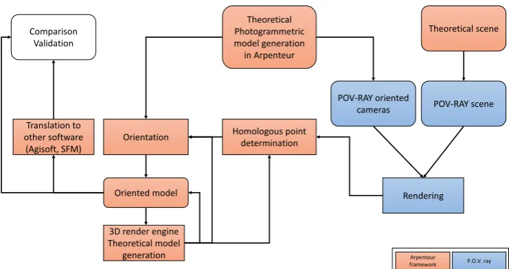
Theoretical Photogrammetric model generation in Arpenteur
Rendering Translation to
other software (Agisoft, SFM) Comparison
Validation
POV-RAY oriented cameras
Theoretical scene
POV-RAY scene
Orientation
Oriented model
Homologous point determination
3D render engine Theoretical model
generation Arpenteur
framework P.O.V. ray
Figure 1. synoptic schema of theoretical model generation process.
2. THEORETICAL MODEL GENERATION
We call photogrammetric model the composition of a set of oriented photographs (with valid Internal and External Orientation) and a set of 3D points with the corresponding 2D observations.
Each photographs is associated with a camera (an image capture device) with intrinsic parameters as focal length, sensor size (most of the time in mm), digital frame size (in pixels) for digital cameras, the pixel shape, a distortion model and the coordinates of the principal point. Finally Internal Orientation has a transformation to pass from the camera reference system in millimeters to the digital image reference system in pixel. External Orientation is composed by rotation and translation transforms (R and T respectively) parameters determinated by a relative orientation or more generally a bundle adjustment. The application dedicated to theoretical model generation produce photogrammetric models in which all of these component and parameters have exact values and EO parameters can be computed without residuals.
2.1 Model generation
When the camera calibrations and the photograph dispositions template around a scene represented by a set of 3D points are chosen, the full photogrammetric model is generated. The 3D point set can be arranged on a cube, a sphere or it can be imported from another source. With all information, a complete photogrammetric model is generated and 2D observations are obtained by 3D point projections on all photographs.
Four predefined dispositions are available. The template of couple enables to produce a pair of oriented photographs that can be used for the validation of relative orientation processes. This template can be parameterized with the basis of the couple and the rotations applied to the photographs by defining omega, phi and kappa angles. The template of triple is quite similar to the couple one but enables to use three photographs. The template of grid simulates a regular coverage of terrain. This configuration can be used to validate an aerial photogrammetric survey system or the coverage of an underwater site and can be parameterized with number of photographs to distribute along a grid of given size. Finally, the last template describes a repartition of the photographs along an ellipsoid. This orbital template can be parameterized by the size of its major and minor axes and the number of photographs stations at its equator and meridian.
3. USE OF THEORETICAL MODEL
Even if theoretical models enable to evaluate conventional photogrammetry systems, they are not suitable for the evaluation of the ones based on the extraction of image features. Indeed, it not possible to generate realistic photographs (with textured objects, variable lighting, atmospheric effects) directly from our theoretical models. Some Computer Generated Imagery softwares provide such functionalities. We chose to use Persistence Of Vision – Ray Tracing (POV-RAY) language(Collins), because it is easy to model the camera by adding the intrinsic parameters of a real camera.
This tool renders a scene described by a POV file as a photograph. Interests of POV are its highly configurable lightning of a scene, objects material and rendering effects. International Archives of the Photogrammetry, Remote Sensing and Spatial Information Sciences, Volume XL-5/W2, 2013
Figure 2. PovRay camera presentation.
The default camera in POV-Ray scene uses perspective projection. The intrinsic parameters of the camera are defined by location, right and up (see Figure 2). Location parameter defines the position of the camera in the scene. The right and up define the sensor dimension in millimeters.
J. F. Plana (Plana, 2008) provides realistic synthetic stereo datasets in order to test any stereo 3D reconstruction and motion estimation algorithm using Mini cooper and Building model which was created by Gilles Tran (Tran, 1993).
The use of calibrated cameras as component of a POV-Ray rendering can be generalized by translating their intrinsic and extrinsic parameters into POV-Ray's language.
The POV-Ray camera object describes both rendering device and its position. It is possible to integrate calibrated camera's intrinsic and extrinsic parameters to the POV-Ray object to make the rendering process realistic. If we denote the focal length in millimeters, frame_width and frame_height the dimensions of the sensor in millimeters and image_width and image_height the dimensions of the produced images in pixel. The up and right parameters are scaled by the sensor size in millimetres and as the direction of the camera is assimilated to the optic axe, the distance between the optic centre and the sensor is expressed by scaling the direction with the focal length. We choose to respect vision standard with assimilation of the optic centre to the origin of the camera object referential and with the assimilation of the optic axe to the Z unit vector of the camera object referential.
The position of the POV-Ray camera object can be obtained from camera extrinsic parameters (i.e. External Orientation). If we denote x, y and z the location vector components and omega, phi and kappa the three rotation angles expressed with the Kraus aerial convention (Kraus, 1997), we can extends the POV-Ray camera to take in account the photograph position. POV-Ray relies on an indirect referential (left-handed) for 3D positioning. For this reason, an additional parameterization has to be done if the camera parameters are originally expressed within a direct referential (right-handed). A zfactor value can be added to the POV-Ray object description to handle the combination of direct and indirect referential. The zfactor value is -1 if the original camera is described within a direct referential and 1 if it is described within an indirect referential. The POV-Ray camera object becomes:
#declare mycamera = Camera { perspective
location <0, 0,0> right x*frame_width up y*frame_height
direction <0,0, 1> * focal_length rotate <0, 0, kappa>
rotate <0, phi * zfactor, 0> rotate <omega * zfactor, 0, 0> translate <x, y,z * zfactor> }
It should be noticed that it is not possible to integrate distortion representation within a POV-Ray scene description. Therefore,
post processing is necessary if the produced images have to take into account distortion.
3.1 External orientation computation
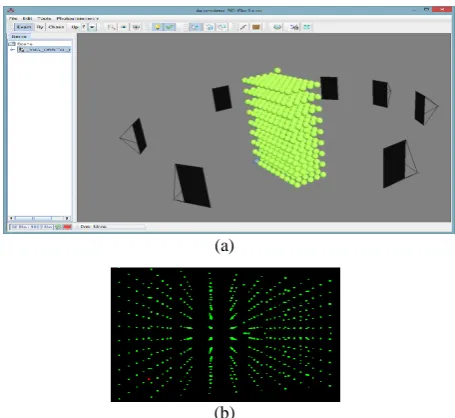
Recently, many methods to compute the relative orientation have been proposed (Heipke, 1997; Kalantari et alii, 2009; Karjalainen et alii, 2006; Nister, 2004; Seedahmed, 2006). In our framework, we have implemented five-point algorithm (Stewenius et alii, 2006) to compute the relative orientation and bundle adjustment (Fusiello & Irsara, 2010; Lourakis & Argyros, 2009; Lourakis & Argyros, 2005) to optimize the result in terms of reprojection error. To validate these methods, we don’t need model with textured images this is why we generated a theoretical model with Arpenteur. This model contains a set of 3D points and their projections (2D points) on several images (see fig).
(a)
(b)
Figure 3. (a) Theoretical model with 19 images and set of 3D points generated with Arpenteur framework (a screenshot from Arpenteur viewer). (b) a generated image with the projection of 3D points by Arpenteur framework.
By knowing the geometry of this model and the 2D points on each images, we computed an incremental relative orientation using five-point algorithm. First we compute all possible stereo-pair and compute for each a quality estimator, a connectivity graph is computed and a path inside the graph is computed for orienting all photographs. The path root, i.e. the first stereo-pair is chosen according to the quality estimator and the connectivity of the two photographs. Each time a stereo-pair with a common photo is added the block size increase and a global BA is done to optimize the reprojection error.
The process iterate as long as new stereo-pair candidate are available. This method is robust but not convenient for a big quantity of photograph. Before the orientation computation all the path are seen in the graph and according to the photo connectivity a set of oriented photograph can be computed if it is not possible to compute a unique block with all the oriented photographs.
To validate this method, we made two tests, for the first one, we compute in each step the projection error (RMS) and we check that this error is less than 10-3. For the second we compare the calculated angles with the angles of the theoretical model. All tests performed with theoretical Arpenteur model give a good result with very low RMS. To make a significant test, we made another test with model generated with POV-Ray by adding a set of sphere on the scene. For this model, we International Archives of the Photogrammetry, Remote Sensing and Spatial Information Sciences, Volume XL-5/W2, 2013
generated two strips of images (see Figure 4); in each strip we generated three images. Knowing the geometry of the scene (intrinsic and extrinsic parameters), we compute the project of sphere centers on each images which will produce a set of homologous points.
From these homologous points, we will compute the incremental orientation to validate the relative orientation between pairs of images and the bundle adjustment accuracy. Next table summarize some results obtained on the model with Arpenteur framework and a comparison with PhotoScan, we can notice that the different between angles from our framework and the angles from PhotoScan is 180 degree on each angle; this difference has no impact on the rotation of camera because it is applied on all angles simultaneously.
Image 2 Image 5
Theoretical model from
POV-Ray data
Omega 181,00 210,00
Phi 179,00 179,00
Kappa 181,00 181,00
Computed model
Omega 180,99 209,99
Phi 178,99 179,00005
Kappa 180,99 181,00001
Agisoft PhotoScan
Omega -179.96 -150.98
Phi -0.00020 0.616
Kappa 0.09 0.43
Table 1. External orientation, comparison between data from POV-Ray, results from Arpenteur framework and Agisoft PhotoScan.
Figure 4. PhotoScan 3D model.
3.2 Feature extraction comparison
After the validation step of the relative orientation computation, we seek to find the best algorithm to use which will give us a good result in terms of processing time and the quality of features.
There are a lot of methods for features extraction, in our previous work (Mahiddine et alii, 2012), we made an investigation to find a pre-processing method that can increase the repeatability of SIFT and SURF and we found that SIFT gave good results in terms of number of features detected and quality.
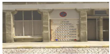
Figure 5. Generated images with POV-Ray.
We generated from POV-Ray 12 images from virtual scene, where we know all geometry parameters of this scene. To compare between feature extractors algorithms, we took a pair of images (see Figure 5) and we have applied some algorithms of features extraction to compare them in terms of time and number of features. Table 2 shows that FAST gives the largest number of features, SURF is the faster but gives just some features. To validate the quality of these features we used k-Nearest Neighbour algorithm with kd-tree like proposed by D. Lowe to find corresponding points
We found that SIFT descriptor (Lowe, 2004) gives the best results (see Figure 6) despite the presence of repeating texture like in the wall of the building and the floor. FAST detector (Rosten et alii, 2010) gives a lot of features in very short time but the result of matching show the presence of a lot of false matches. SURF(Herbert Bay, 2006) gives also suitable results with less matches points compared to SIFT which can be enough to compute the relative orientation.
First image Second image
Features Time (s) Features Times(s)
SIFT 1510 0.752 1483 0.713
SURF 471 0.179 467 0.074
FAST 16965 0.77 17555 0.71
Table 2. Processing time comparison.
Figure 6. Matching features results.
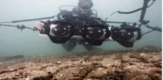
3.3 Trifocal sensor
Trifocal sensor, with three aligned and synchronized digital camera, is very convenient in underwater survey. The diver is able to manage the set of three cameras and for each triplet it can measure dynamic organism as gorgona for example. This device is used by marine biologist as well as underwater archaeologist.
Figure 7. Underwater survey made with three digital cameras associated and synchronized on a rigid bar. (Photo P. Drap).
0 500 1000 1500
SIFT SURF FAST +
Brief International Archives of the Photogrammetry, Remote Sensing and Spatial Information Sciences, Volume XL-5/W2, 2013
Special development were done in order to compute External orientation of such a triple and a corresponding theoretical model can be generated for validating the development. The trifocal tensor plays the analogous role in three views to that played by the fundamental matrix in two views (Hartley & Zisserman, 2003). In other words, it encapsulates and establishes the projective geometric relations between three views of a scene.
There are several incidence relations between three views: line-line-line correspondence, line-line-line correspondence, point-line-point correspondence, point-point-line correspondence and point-point-point correspondence. Therefore, there are many ways that the trifocal tensor may be approached depending on the incidence relation considered. In this paper, only the estimation of trifocal tensor based on point-point-point correspondence (Figure 8) will be developed.
Figure 8. Incidence relation: Point-point-point. The trifocal tensor is composed by three matrices: T = (T1, T2, T3). Itcan be
used to express the incidence relationship for the points of correspondence.
Let’s X a 3D point projecting to image points x= (x, y, 1), x’= (x’, y’, 1) and x”= (x”, y”, 1) respectively in the three images as it is shown in the Figure.
According to (Hartley & Zisserman, 2003), the incidence relation point-point-point is tri-linear relations in the coordinates of the image points. These equations are given by the relation (1):
[ ] (∑ ) [ ] (1)
With:
[ ] [
]
and
[ ] [
]
The system is composed by 9 tri-linear equations, but only 4 equations are linearly independent. Thereby, we need at least 7 point correspondences to solve the linear system in order to determine the 27 elements (9 of each trifocal tensor matrix: T1,
T2 and T3) of the trifocal tensor. To do this, we use the algebraic
minimization algorithm suggested by (Hartley & Zisserman, 2003).
Once the three matrices of the trifocal tensor are computed, the projection camera matrices P= [I | 0], P’ and P’’ of the first, the second and the third camera respectively could be easily according the relations (2) and (3):
[[ ] ] (2)
[ [ ] ] (3)
Where and are the epipoles in the second and third images corresponding to the first camera center. They are the common
perpendicular to the left (respectively right) null-vectors of the three matrices T1, T2 and T3.
Figure 9. Trifocal model generated with PhotoScan.
3.4 3D Model generation with SFM software
3.4.1 Agisoft PhotoScan
It is based on multi-view 3D reconstruction technology. This software offers a full control of the whole pipeline for 3D model reconstruction and facilitates the use of calibrated and un-calibrated images. We used the models produced by this software in Arpenteur framework for validation of photogrammetric processes
Figure 10. Example of image generated with POV-Ray.
3.4.2 Control point.
Models produced by different SFM softwares are by default not dedicated to photogrammetry tasks because the point clouds provided with this kind of software have arbitrary scale and position in the space.
Figure 11. 3D model generation with control points.
So, we cannot evaluate the metric accuracy without control points in the scene, for this reason, we use several spheres with known position in space to obtain an Absolute Orientation, using these points in the final BA (see Figure 11).
These control points will help us to compare the accuracy of the produced 3D model with Arpenteur framework and to compare it with models obtained with: Agisoft or Visual SFM. In (Lo Brutto, 2012) authors evaluate the performance of several softwares and 3D web services to analyse the accuracy of 3D models.
We have to note that the only error introduced in the model is the Control Point Identification on the photograph in the Photoscan software by Agisoft. Indeed these points have to be International Archives of the Photogrammetry, Remote Sensing and Spatial Information Sciences, Volume XL-5/W2, 2013
marked manually by the user on the photographs. We are currently working on generating automatically Photoscan project from Arpenteur models to solve this problem.
4. CONCLUSIONS
We have presented in this paper different theoretical models generated from Arpenteur framework (case of model without texture) or generated by POV-Ray for model with texture. To better choose the best feature extractor, we used a model from POV-Ray with texture, however, this model provides a lot of false match which is due to the texture repetition, fortunately, we rarely crossed such cases in real life. All the same, after a several tests, we found that repeatability of SIFT descriptor and SURF are good enough to produce good matched points that we can use for external orientation computation, on the other side FAST detector gives the largest number of features but the use of BRIEF descriptor (Calonder et alii, 2010) is not effective in this kind of scene with texture repetition.
We also try to validate the step of external orientation computation. For this step we can notice two tests, the first one is the test on multi-view model which include multiple stereo models where we attempted to validation the method of five-point and the optimisation with bundle adjustment. From results that we obtained we can deduce that our implementations of five-point algorithm and bundle adjustment work well compared to the results obtained with Agisoft PhotoScan. The second test was about model which used a tri-focal sensor. Tri-focal sensors are used in underwater imaging for images stitching or 3D reconstruction of the scene, the use of these sensors is a real time saving for divers photographers. Further tests should be done to evaluate the performance of Arpenteur framework to check the accuracy of models obtained.
5. ACKNOWLEDGEMENTS
This work was partially funded by the European Regional Development Fund (FEDER) and the French Inter-Ministry Fund (FUI) for funding research involving both academic
Robust Independent Elementary Features. In Computer Vision-Eccv 2010, Pt Iv. Daniilidis K. & Maragos P. & Paragios N.(Ed.), Vol.: 6314, pp. 778-792, Springer-Verlag Berlin(Pub.), isbn/issn:0302-9743
978-3-642-15560-4.
Collins D. K. Buck and A. A. "POV-ray - the persistence of vision raytracer.". Web page available: http://www.povray.org/
[Last Access date: 04 July 2013].
Drap Pierre, & Grussenmeyer Pierre. (2001, 1-3 October). 3D Geometric modeling from images on the WEB with ARPENTEUR. Paper presented at the In Optical Measurement Techniques, Special Session on Multimedia in
Education, Vienna, Austria. Kahmen Armin
Grün/Heribert(Ed.), pp.424-432, isbn/issn:3-95014926061. Fusiello Andrea, & Irsara Luca. (2010). Quasi-Euclidean epipolar
rectification of uncalibrated images. Machine Vision and Applications, pp.1-8, Springer Berlin / Heidelberg(Pub.), isbn/issn:0932-8092.
Hartley Richard, & Zisserman Andrew. (2003). Multiple view geometry in computer vision. Cambridge, UK; New York Cambridge University Press.
Heipke C. (1997). Automation of interior, relative, and absolute orientation. Isprs Journal of Photogrammetry and Remote Sensing, Vol.:52, pp.1-19, isbn/issn:0924-2716.
Herbert Bay Tinne Tuytelaars and Luc Van Gool (2006). SURF: Speeded Up Robust Features. Proceedings of the 9th
European Conference on Computer Vision, Springer LNCS,
Vol.:3951, part 1, pp.404--417.
Kalantari Mahzad, Jung Franck, Guedon Jean Pierre, & Paparoditis Nicolas. (2009, 13/01). The Five Points Pose Problem : A New and Accurate Solution Adapted to any Geometric Configuration. Paper presented at the The Pacific-Rim Symposium on Image and Video Technology (PSIVT), Tokyo, Japon.
Karjalainen M., Hyyppa J., & Kuittinen R. (2006). Determination of exterior orientation using linear features from vector maps.
Photogrammetric Record, Vol.:21, pp.329-341, isbn/issn:0031-868X.
Kraus Karl. (1997). Photogrammetry vol 1 & 2 (Stewardson Peter, Trans. Dummlerbush ed. Vol. 2). Bonn, Germany.
Lo Brutto M.; Meli, P. (2012). Computer Vision Tools for 3D Modelling in Archaeology. International Euro-Mediterranean Conference (EuroMed).
Lourakis M. L. A., & Argyros A. A. (2005, 17-21 Oct. 2005). Is Levenberg-Marquardt the most efficient optimization algorithm for implementing bundle adjustment? Paper presented at the Computer Vision, 2005. ICCV 2005. Tenth IEEE International Conference on. Vol.:2, pp.1526-1531 Vol. 1522, isbn/issn:1550-5499.
Lourakis Manolis, & Argyros Antonis. (2009). SBA: A software package for generic sparse bundle adjustment. ACM Trans. Math. Softw.,, Vol.:36, pp.1-30.
Lowe David. (2004). Distinctive image features from scale-invariant keypoints. International Journal of Computer Vision,
Vol.:60, pp.91-110.
Mahiddine Amine, Seinturier Julien, Peloso Daniela, Boï Jean-Marc, Drap Pierre, & Merad Djamel. (2012, June 25-28).
Performances Analysis of Underwater Image Preprocessing Techniques on the Repeatability of SIFT and SURF Descriptors. Paper presented at the WSCG 2012: 20th International Conferences in Central Europe on Computer Graphics, Visualization and Computer Vision, Pilsen, Czech Republic. Skala Vaclav(Ed.), Vol.:Communications proceedings II, pp.275-282, isbn/issn:978-80-86943-79-4. Nister David. (2004). An efficient Solution to the Five-point Relative
Pose Problem. Ieee Transactions on Pattern Analysis and Machine Intelligence, Vol.:26, pp.756 770.
Plana Jordi Ferrer. (2008). Pobray-based Ground truth Generator. Web page available: http://uvl.udg.edu/ [Last Access date: 04 July 2013].
Rosten Edward, Porter R., & Drummond Tom. (2010). Faster and Better: A Machine Learning Approach to Corner Detection.
Pattern Analysis and Machine Intelligence, IEEE Transactions on, Vol.:32, pp.105-119, isbn/issn:0162-8828. Seedahmed G. H. (2006). Direct retrieval of exterior orientation
parameters using a 2D projective transformation.
Photogrammetric Record, Vol.:21, pp.211-231, isbn/issn:0031-868X.
Snavely N., Simon I., Goesele M., Szeliski R., & Seitz S. M. (2010). Scene Reconstruction and Visualization From Community Photo Collections. Proceedings of the Ieee, Vol.:98, pp.1370-1390, isbn/issn:0018-9219.
Stewenius Henrik, Engels C., & Nister David. (2006). Recent developments on direct relative orientation. Isprs Journal of Photogrammetry and Remote Sensing, Vol.:60, pp.284-294, isbn/issn:0924-2716.
Tran Gilles. (1993). "Mini Cooper and building (POV-Ray)" ,. Web
page available:
http://oyonale.com/modeles.php?lang=en&page=39 [Last
Access date: 04 July 2013].