SINGLE-LAYER LASER SCANNER FOR DETECTION AND LOCALIZATION OF
UNMANNED SWARM MEMBERS
T. Kr¨ugera,∗, S. Nowaka, J. Matthaeia, and U. Bestmanna
aInstitute of Flight Guidance, Technische Universit¨at Braunschweig, Germany
(th.krueger, stefan.nowak, j.matthaei, u.bestmann)@tu-braunschweig.de
KEY WORDS:Extra-terrestrial, Aerial, Robotic, LIDAR, Tracking, Fusion, Navigation
ABSTRACT:
In the presented work unmanned vehicles are used for an extra-terrestrial exploration mission. In this scenario a high factor of redun-dancy for all systems has to be considered. Defective sensors for instance cannot be repaired and any damage has to be compensated through an intelligent use of the remaining sensors and a robust data fusion. Therefore this work proposes the utilization of a single-layer laser scanner, which is used for Simultaneous Localization And Mapping (SLAM) for the compensation of a defective relative positioning system. An Extended Kalman-Filter (EKF) with error states is used to perform the loosely coupled integration of the esti-mated states and the measured relative position in discrete updates. Subsequently the improvement of the navigation solution onboard an Unmanned Aerial Vehicles (UAV) can be estimated. The outcomes of a specifically developed simulation will be shown, delivering theoretic results for the proposed method. A flight test is done finally in order to prove the capability of the laser scanner to detect and locate an UAV.
1 INTRODUCTION
The motivation of this work is the theoretical exploration of the largest known canyon system of the solar system, the Valles Ma-rineris, on planet Mars. Due to the geological hazards in this area such an exploration should preferably be realized by a swarm of UAVs and Unmanned Ground Vehicles (UGVs). Past and re-cent exploratory missions on the surface of Mars made use of remotely controlled ground vehicles. Because the transmission of signals from Mars to Earth and back take a considerable time, a direct manual control of flying robots is not possible. Therefore a fully automatic operation has to be considered which results in a central issue, the development of an innovative fault-tolerant and robust automatization. Repairing single systems or an entire robot is not possible, therefore the highest possible factor of re-dundancy has to be provided and a failure of single sensors or subsystems must not lead to a major degradation or loss of a ve-hicle.
For automatic acting robots often an Inertial Navigation System (INS) is used. Such a system incorporates an Inertial Measure-ment Unit (IMU), typically based on Micro-Electro-Mechanical Systems (MEMS). Though at least one additional navigation sys-tem, commonly a Global Navigation Satellite System (GNSS), has to support the INS, which otherwise would accumulate sen-sor errors and the navigation solution would become unstable. In GNSS denied environments, like in the case at hand, other sen-sors and supporting navigation subsystems must be provided for a safe automatic operation of these vehicles. These could consist of rangefinders, optical systems, air data sensors, relative posi-tioning systems and swarm navigation methods.
One of many considered subsystems is the so called Leap Frog Navigation, see (Opshaug (2003)). The essential component is a relative positioning system based on radio telemetry links and multiple swarm members. Only a small number of swarm par-ticipants are moving in certain bounds towards unexplored areas. All other robots maintain their positions and serve as transmit-ters, providing relative positioning for the moving robots. Ad-ditionally navigation messages will be exchanged among them. This enables a robust navigation solution for the UAVs as well as the UGVs for long distances. With respect to redundancy another
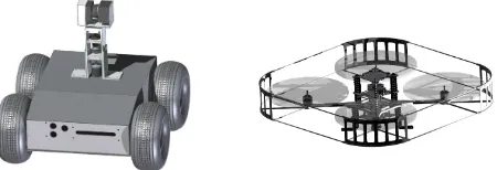
Figure 1: Robots used for terrestrial experiments. On the left: UGV (DrRobot Jaguar 4x4 Wheel). On the right: UAV (Ascend-ing Technologies Pelican)
way has to be found to locate a robot relative to other swarm members in case of a failure of the relative positioning system. This task will be the focus of the presented work. A method will be introduced which allows an UAV to locate itself relative to a mobile ground rover using singe-layer laser scanner mea-surements from that UGV. The ground rovers are equipped with a single-layer laser scanner mounted on a rotating turret with a precise angle measurement. Therefore it can perform three- di-mensional sensing for SLAM algorithms. However this system can also be used to detect and localize a nearby swarm partici-pant and thus could compensate for a defective relative position-ing system. In that case the Leap Frog Navigation system as well as a stable navigation solution could be maintained.
A simulation environment, which incorporates the detection and the relative positioning of an UAV by the laser scanner of the UGV, has been developed in order to proof this concept prior to flight tests. All values, physical constants and coordinate systems are referred to Earth. The transfer of such a method to Mars en-vironment has to be considered, but is not the focus of this work. Figure (1) shows the robotic systems which are used for the ter-restrial experiments.
1.1 Related Work
1.1.1 Cinetheodolites Cinetheodolites are photographic instru-ments for the acquisition of trajectory data from flying objects. A tracking mechanism allows a continuous monitoring of the tra-jectory. The localization principle is a vision-based azimuth and elevation measurement. Long range three-dimensional position triangulation can be done with at least two stations, or combined angle and laser-based distance measurements from a single sta-tion. These devices have a mass of several 100 kg and therefore are limited to special test sites or large moving platforms.
1.1.2 Mono-/Stereo-Camera Systems These systems are typ-ically coacting with a pan-tilt camera mount and are able to track an UAV based on features detected in the image plane. Knowing the dimensions of the object that is being tracked, a distance esti-mation can be performed. Advantageous are noticeable marks at-tached to the UAV to improve the visibility of the vehicle. Are at least three marks distributed at the edges of the vehicle an attitude estimation can be accomplished. By doing so a three-dimensional attitude and position measurement can be done.
Stereo-camera systems, used e.g. in (Markus et al. (2009)), make use of two cameras in order to measure the distance to an object with the help of the displacement of the object in the two im-age planes. In order to achieve a continuous three-dimensional state estimation of a tracked vehicle, these systems have to be setup with a pan-tilt camera mount, similar to the mono-camera systems. The advantages of such camera based systems are the low costs of the cameras compared to other systems and the high update rates. The disadvantages are the range, the accuracy es-pecially at long ranges, the influences of light and visibility con-ditions and the mandatory calibration of the cameras. Also only one single UAV at the time can be tracked. A stereo-camera sys-tem with landmark and feature extraction is already used within this project for supporting the navigation system. Hence the use of this system for relative positioning of swarm members may be investigated further.
1.1.3 Multi-Camera Systems Typically used for indoor ap-plications these systems consist of several cameras mounted at different positions in a limited space. Due to the tracking of a vehicle from different perspectives a full state observation can be done, see e.g. (Oh et al. (2011)) or (Mart´ınez et al. (2011)). Because these systems need such an infrastructure, they cannot be used well for outdoor exploration scenarios. One way to use such a system in the current scenario is to mount cameras on each rover. Placing the rovers around an UAV, the rovers could be used as infrastructure and could perform a multi-camera state measure-ment of the UAV in between.
1.1.4 Total Stations Total stations are mobile laser based dis-tance measuring devices, typically designed for geodesy and civil engineering. An automatic tracking function, based on a prism tracking, makes these devices suitable to track slow UAVs. The maximum detection ranges are between 300 m and 1000 m and the accuracy is better than one centimeter (Andert et al. (2012)). However because of the relatively high costs such a system wil not be applicable within this work.
2 SIMULATION OF LASER SCANNER LOCALIZATION
In this part the simulation environment for the proposed method is being introduced. The detection and localization of a moving UAV is simulated considering the capabilities of the laser scanner sensor and the UAV properties, see (Frisch (2013)) for further details.
2.1 Simulation of the UAV
First, an existing simulation environment including the dynamic model of the UAV is being used to generate the desired flight paths. This simulation delivers the ideal states of the vehicle in-cluding position, velocity and attitude, as well as the simulated ideal IMU measurements and more realistic IMU measurements from a sensor error model. The position is provided in WGS84 coordinates as well as in a navigation frame (indexn), which is a geodetic system with the origin at the initial position of the UAV.
In the dynamic simulation only a point mass is considered. In or-der to generate realistic laser scanner measurements an object has to be built around that point mass which can be detected by the laser scanner plane. The object is generated using eight points with specific distances from the point mass. Connecting these eight points they generate six surfaces which match the dimen-sions of the real UAV. The cuboid is than being transferred to its flight path which is described by the simulated position and attitude states.
2.2 Detection by the Laser Scanner
In this section the detection of the previously generated object is being discribed. First, an infinite intersecting line of the laser scanner plane with the first surface of the object is being calcu-lated, see Figure (2).
Figure 2: Calculation of intersecting points between laser scanner plane and UAV cuboid
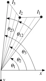
Between this infinite line and the connection lines of correspond-ing edgesEiof the surface, intersecting points are being gener-ated. This is being done for every surface that was hit by the laser scanner plane.
As long as the laser plane is not parallel to one of the surfaces of the cuboid, exact three intersecting points should be found. A logic is detecting the three nearest pointsIiwhich represent the outer bounds of the laser scanner measurement. Afterwards, the anglesθ12 andθ23between these three points are used to deter-mine how many laser rays would have hit the object, see Fig-ure (3). After all laser rays which would hit the object are iden-tified a laser scanner error model is being applied. This sensor model was built from multiple reference measurements and de-termines the stochastic and absolute error sources, see (Zitterell (2004)) for further details.
The simulation considers a rotating laser scanner as well as a moving UGV. The output of the introduced simulation are simu-lated laser scanner measurements, which are available in the same data format as the data of the real laser scanner, Hokuyo UTM-30LX-EW. Therefore it is possible to process both data sources in the same way without any changes in the calculations.
3 DATA PROCESSING
Certain simplifications have been done in order to reduce the complexity for the first experiments. Therefore it has been as-sumed that the surrounding environment and foreign objects will not be detected by the laser scanner.
The data of one entire scan consists of a vector with 1080 dis-tancesdr, representing all laser rays. The corresponding angleθr of each laser ray can be calculated using the indexrof the ray in the vector, the starting angleθ1=−45 ° and the difference angle θδ=0.25 ° between each laser ray, see Equation (1).
θr=θ1+r·θδ (1)
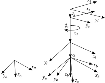
The detected points from one single scan are combined to a sur-face area. The center of gravity of this area defines the measured position of the UAV. This position is then transformed in order to serve as supporting information for the sensor data fusion. There-fore the rotary encoder of the laser scanner turret (indext) de-livers the angleφs of the scanner (indexs) for each scan. The received spherical coordinates can now be transformed in a navi-gation frame or the WGS84 system using:
• the rotation from the body-fixed (indexb) to the geodetic coordinate system of the UGV (indexg),
• the displacement of the laser sensor on the UGV (indexl)
• and the translation of the UGV itself in the navigation frame.
yl
xl
zl
ys
zs
xs
yt
zt xt
yb
zb
xb
xg
zg
yg
φs
yn
xn
zn
Figure 4: Overview of the different used coordinate systems
The different coordinate systems are shown in Figure (4). Ran-dom measurements from the real sensor could lead to wrong de-tections. Therefore multiple consecutive rays during one single scan have to detect an object in order to declare it as the UAV. The number of the threshold is dependent on the distance from the UAV to the laser scanner. The shorter the distance, the more rays have to detect the UAV. Additionally the object has to be detected in multiple consecutive complete scans.
4 INTEGRATED NAVIGATION SYSTEM
The multi-sensor data fusion of the different subsystems is done by an Extended Kalman-Filter. This algorithm loosely couples the measured position information which are delivered and pro-cessed by the subsystems and estimates corrections for the INS, see Figure (5). Thus the solution of the INS can be improved, which is important if no supporting information are available for a certain time. The used rovers have been equipped with an ADIS16488 MEMS IMU from Analog Devices for the measure-ment of the body-fixed rates and accelerations.
Figure 5: Integration method of the laser scanner based relative positioning system
Starting from the initial states, this system propagates the iner-tial navigation solution until an external measurement is avail-able, see (Titterton and Weston (2005)) for further details. At this point an update is being done which processes the measurement and calculates the corrections for all states, dependent on the dif-ference between the estimated and measured position. Figure (6) shows an overview of the detailed filter calculations.
Figure 6: Overview of the Extended Kalman-Filter flow chart
and will be delivered from each subsystem. Rgives information about the confidence of the measurement. The process noise co-variance matrixQon the other hand gives an information how good the IMU based estimates are. If Q<<Rthe system is trusted more than the measurement and ifQ>>Rthe other way around accordingly. The values forRhave been empirically de-termined during the simulation and primarily adopted for the real sensor. For further details on the implementation of the Extended Kalman-Filter see (Crassidis (2005)) and (Wendel (2010)).
5 RESULTS
In the following section the results of the simulation and a flight test are being shown. The first part of the simulation section is considering the results from the detection simulation. After-wards, the second part will show the results of the integrated nav-igation system, where the detected relative position of the UAV is used to support the INS. Finally a flight test has been done in order to prove the capability of the laser scanner to detect a flying UAV.
5.1 Results of UAV Detection Simulation
The simulation uses the flight mechanic simulation of the quadro-copter and the cuboid computation as introduced in 2.1. Further-more, the intersections are being calculated and a measurement vector similar to the real sensor is produced as proposed in 2.2. In Figure (7) on the left-hand side the visualization of the laser scanner plane and the cuboid can be seen, the cuboid has been magnified for a better visibility. The visualization of the trans-formed measurement in thel-plane is being shown on the right-hand side. Because only the outer bounds of the cuboid are being detected, there is an offset between 0.1 m and 0.42 m to the ref-erence. Further investigations could prove if it possible to com-pensate for this effect. Presuambly the known attitude of the UAV could be used to reconstruct its contours and to estimate its center of gravity.
Figure 7: On the left: Visualization of the detection of the UAV with the laser scanner. On the right: Measurement in laser scan-ner plane which is delivered by the simulation
5.2 Sensor Fusion of Simulated Data
In this section the results for the integrated navigation system are presented. For first evaluations, in this scenario the UGV is placed fixed at a specific location near the starting location of the UAV and the laser scanner is not rotating . The UAV is flying in a circular shape around the UGV, with an increasing altitude and is being detected twice for one circuit. The simulated IMU mea-surements are used for the strap-down calculation of the INS and the simulated detected UAV positions are used as measurement for the Extended Kalman-Filter update. The results are shown in Figure (8) in the navigation frame, starting from the take-off position of the UAV. It can be seen that the integrated navigation
Figure 8: Estimated flight path of pure INS, integrated navigation solution and reference during the simulation
system is being updated with the relative position of the UAV dur-ing each detection and the corrections of the position estimations are done.
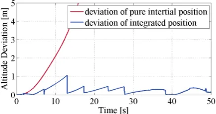
Additionally in Figure (9) the deviation of the altitude estima-tion of the integrated and the pure inertial navigaestima-tion system are shown. The deviation of the pure inertial navigation system af-ter a time of 50 s is about 54 m and the position error is about 139 m, both were not plotted completed for the benefit of a better overview. But in both cases it can be seen, that the pure inertial navigation solution is not stable and the deviation increases con-siderable amounts after a short time. On the contrary, together with the calculated corrections for the INS, the integrated naviga-tion system leads to a stable naviganaviga-tion system.
Figure 9: Deviation of estimated altitude of INS and integrated navigation solution
The simulation results are very promising to prove the feasibility of the proposed concept. However a real flight test is needed in order to validate the concept finally.
6 FIELD TEST WITH UAV AND UGV
times. Although the UAV could access the laser scanner data on board of the ground vehicle via a communication link, the data of the flight test was recorded and evaluated in post-processing.
Figure 10: Field Test with UGV and UAV on model plane airfield
Figure (11) shows the measurements from the laser scanner of the UGV in the laser scanner plane. The lift-off of the UAV can be seen clearly based on the green point cloud. These points cor-respond to the time of lift-off recorded on the UAV. The blue point clouds show the measurements during each turn of the UAV around the UGV. Finally the red point cloud corresponds to the time of the landing of the UAV at the end of five circles and 50 s of flight time.
Figure 11: Laser scanner plane during the test flight
A magnified section of previous figure is shown in Figure (12). The dimensions (0.6 m length and 0.25 m heigth) and contours of the quadrocopter can be seen clearly.
Figure 12: Magnified section of laser scanner plane during the test flight
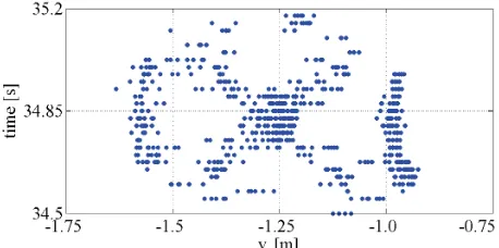
Figure (13) shows the UAV while it flies through the laser scan-ner plane. The measured distances to the UAV inyl direction is sequentially plotted against the time since take-off. From this perspective especially the propeller protection frame and the mo-tor booms and can be distinguished well. Such a result was not expected, further investigations could consider if it is possible to
estimate the attitude, e.g. the heading, of the UAV based on this view. It has been proved that in certain limits the laser scanner is
Figure 13: Detected UAV during flight through laser scanner plane, plotted against time
suitable to detect and locate a flying UAV. With the help of this flight test the basis for further investigations has been created. The laser measurements will be processed and transformed like the simulated measurements in order to achieve the supporting positioning information. Further evaluation of the data and the fusion of the recorded data with the INS solution of the UAV will be done in the near future.
7 CONCLUSIONS
This work describes the attempt to use a single-layer laser scan-ner, which is normally used for SLAM navigation, for the local-ization of a flying UAV. A simulation environment has been used in order to proof the concept prior to real tests. Therefore the detection of a virtual object and a realistic sensor model were im-plemented. Real flight tests showed to potential of this system and proved the capability of the laser scanner to detect and lo-cate an UAV. Further flight tests will show wether the simulation results of the integrated navigation system can be confirmed and to prove the funcionality of this system with a moving UGV and rotationg laser scanner.
The disadvantages of this system are clearly the limited range with this specific laser scanner and the missing tracking capabil-ity. A combination of the laser scanner and a camera tracking system would give better results and could be considered further.
If this system can compensate for a defective relative position-ing system of an unmanned robot swarm it would contribute to a reduced mission failure of an exploration scenario on Mars. On the other hand it could also be used on Earth, for instance when unmanned robots are used for the exploration in catastrophic sce-narios.
8 ACKNOWLEDGEMENTS
This work has been performed in the framework of the project VaMEx (Valles Marineris Explorer) which is partly funded by the Federal Ministry of Economics and Technology administered by DLR Space Agency (FKZ 50NA1212) and the Bavarian Ministry of Economic Affairs, Infrastructure, Transport and Technology administered by IABG GmbH (ZB 20-8-3410.2-12-2012).
9 REFERENCES
Andert, F., Polzin, H., Dittrich, J., Becker, M., Batzdorfer, S. and Hecker, P., 2012. Aerial Tracking and GNSS-Reference Localization with a Robotic Total Station. AIAA In-fotech@Aerospace.
Crassidis, J. L., 2005. Sigma-Point Kalman Filtering for Inte-grated GPS and Inertial Navigation. AIAA Guidance, Naviga-tion, and Control Conference.
Frisch, T., 2013. Laserscanner zur Relativortung unbemannter Flugsysteme. Bachelor Thesis, Technische Universit¨at Braun-schweig, Institute of Flight Guidance.
Markus, A., Tianguang, Z., Kolja, K. and Martin, B., 2009. Vi-sual Tracking and Control of a Quadcopter using a Stereo Camerasystem and Inertial Sensors. Proceedings of the 2009 IEEE International Conference on Mechatronics and Automa-tion.
Mart´ınez, C., Mondrag´on, I. F., Olivares-M´endez, M. A. and Campoy, P., 2011. On-board and Ground Visual Pose Esti-mation Techniques for UAV Control. Journal of Intelligent & Robotic Systems 61(1-4), pp. 301–320.
Oh, H., Won, D.-Y., Huh, S.-S., Shim, D. H., Tahk, M.-J. and Tsourdos, A., 2011. Indoor UAV Control Using Multi-Camera Visual Feedback. Journal of Intelligent & Robotic Systems 61(1-4), pp. 57–84.
Opshaug, G. R., 2003. A Leapfrog Navigation System, Disser-tation. http://waas.stanford.edu/~wwu/papers/gps/ PDF/Thesis/GuttormROpshaugThesis03.pdf. Accessed: 2013-05-12.
Titterton, D. H. and Weston, J. L., 2005. Strapdown Inertial Nav-igation Technology - 2nd Edition. The Institution of Electrical Engineers.
Wendel, J., 2010. Integrierte Navigationssysteme: Sensordaten-fusion, GPS und Inertiale Navigation - 2nd Edition. Olden-bourg Verlag, M¨unchen.