MOBILE STEREO-MAPPER: A PORTABLE KIT FOR
UNMANNED AERIAL VEHICLES
Julien Li-Chee-Ming a, Costas Armenakis a, Regina Lee b
a Geomatics Engineering, a GeoICT Lab, b Space Engineering Department of Earth and Space Science and Engineering
York University, Toronto, Ontario, Canada {julienli}, {armenc}, {reginal} @yorku.ca
Commission I, WG I/V
KEY WORDS: Mobile Stereo-Mapping Systems, Unmanned Aerial Vehicles, MEMS, 3D mapping, Direct Georeferencing, GPS, IMU, Magnetometer, Sensor and System Calibration
ABSTRACT:
A low-cost portable light-weight mobile stereo-mapping system (MSMS) is under development in the GeoICT Lab, Geomatics Engineering program at York University. The MSMS is designed for remote operation on board unmanned aerial vehicles (UAV) for navigation and rapid collection of 3D spatial data. Pose estimation of the camera sensors is based on single frequency RTK-GPS, loosely coupled in a Kalman filter with MEMS-based IMU. The attitude and heading reference system (AHRS) calculates orientation from the gyro data, aided by accelerometer and magnetometer data to compensate for gyro drift. Two low-cost consumer digital cameras are calibrated and time-synchronized with the GPS/IMU to provide direct georeferenced stereo vision, while a video camera is used for navigation. Object coordinates are determined using rigorous photogrammetric solutions supported by direct georefencing algorithms for accurate pose estimation of the camera sensors. Before the MSMS is considered operational its sensor components and the integrated system itself has to undergo a rigorous calibration process to determine systematic errors and biases and to determine the relative geometry of the sensors. In this paper, the methods and results for system calibration, including camera, boresight and leverarm calibrations are presented. An overall accuracy assessment of the calibrated system is given using a 3D test field.
1. INTRODUCTION
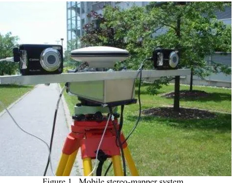
A low-cost mobile stereo-mapping system (MSMS) weighing approximately 1kg is under development in the GeoICT Lab, Geomatics Engineering program at York University (Li-Chee-Ming and Armenakis 2010b). The MSMS, (Figure 1), is portable, is designed for remote operation and is intended to fit onboard unmanned aerial vehicles (UAV) for navigation and rapid collection of 3D spatial data. The MSMS does not use traditional georeferencing techniques such as ground control points (GCPs) based aerial triangulation, thus avoiding the issues associated with the use of GCPs, such as high costs and difficulty in data collection. As a promising alternative, the MSMS implements integrated GPS/IMU to directly georeference the aerial imagery. Current direct georeferencing systems (e.g., POSAV, Applanix, 2011) are designed for larger manned vehicles with much larger payload capacities. The MSMS implements compact MEMS-based solutions suitable for UAVs with small payload capabilities.
The mapping sensors, two Canon A480 digital cameras in stereometric set-up, are calibrated and their exposure times are synchronized to GPS time. Pose estimation of the mapping sensors is based on single frequency RTK-GPS, loosely coupled in a Kalman filter with MEMS-based IMU. The attitude and heading reference system (AHRS) calculates orientation from the gyroscope data and augments these with accelerometer data. The gyroscopic heading is augmented by a magnetometer. For
Figure 1. Mobile stereo-mapper system
the RTK-GPS solution, L1 pseudorange and carrier phase observations are transmitted at 1Hz to the ground control station through the Novatel OEMStar receivers onboard the MSMS and from a nearby GPS base station, respectively. Gyroscope and accelerometer data from an ADIS16364 IMU and data from an HMC5843 magnetometer are logged at 100Hz and 10 Hz, respectively. These observations are synchronized to GPS time using the OEMStar’s pass through logging and transmitted to the ground station at 10Hz. A Linuxstamp 2 microprocessor integrates the sensors and logs the data.
way communication between the MSMS and ground station is established by Xbee-Pro OEM RF Modules including images from the video-navigation camera. The determination of the 3D object coordinates is performed using rigorous photogrammetric solutions in post-mission processing. Before the MSMS is considered operational, its sensor components and the integrated system itself have to undergo a rigorous calibration process to determine systematic errors and biases, and to determine the sensors relative geometry. The various calibration processes are presented in the next sections of this paper. Figure 1 shows the MSMS undergoing system calibration.
2. SYSTEM CALIBRATION
The MSMS accurately extracts 3D point coordinates in the mapping frame using a least squares photogrammetric space intersection. No ground control points are used as the exterior orientation (cameras’ position and orientation at exposure time) and interior orientation (cameras’ interior geometry and lens distortion) are considered known for both cameras at all times. The exterior orientation parameters of both cameras are determined by a combination of GPS and IMU observations, the cameras’ interior orientation parameters by field or laboratory calibration.
The physical relationship between a camera, an inertial measurement unit (IMU), and a GPS antenna in a mobile mapping system (MMS) is given by El-Sheimy (1996) and shown in Figure 2. The model transforms the position of the point of interest measured in the camera coordinate system, ric,
to the position vector in the mapping frame, riM, by using
Equation 1.
)) ( )
( c
i i c GPS b c M b M GPS M
i r t R t R r sr
r (1)
where, at time t, rGPSM is the position of the GPS antenna in the
mapping frame, R is the rotation matrix from the vehicle body bM
frame to the mapping frame, determined by the AHRS, R is cb
the rotation matrix from the camera frame to the vehicle body frame, determined from boresight calibration, rGPSc is the vector
from the GPS antenna to the camera’s perspective center, determined by leverarm calibration, and siis the scale between
the image and the object vectors of object point i determined using photogrammetric techniques. Ellum and El-Sheimy (2002) define three elements of integrated system calibration: leverarm calibration, boresight calibration and camera calibration. Their approach was adopted to perform the system calibration of the MSMS.
2.1 Camera Calibration
Camera calibration can be performed in the laboratory using a calibration 2 or 3D grid or in the field using a network of ground control points, through self-calibration. Self-calibration solves for the extended interior orientation parameters in a least-squares bundle adjustment. That is, the collinearity equations are augmented with additional parameters to account for adjustment of the camera’s interior orientation parameters (IOPs), specifically the calibrated principal point coordinates (xp, yp), lens calibrated focal length (c), the coefficients of
symmetric lens distortion (k1, k2, k3), and the coefficients of the decentering lens distortion (p1, p2). In addition, the camera’s exterior orientation parameters (EOPs), that is, the position (Xo, Yo, Zo) and the orientation (
,
,
) of the camera are solved for.Figure 2. Direct georeferencing model
PhotoModeller’s camera calibration module was used to calibrate the two Canon A480 digital cameras in the laboratory (PhotoModeller, 2011). The cameras were calibrated at the focus setting used to take measurement photographs, i.e. infinity. The autofocus of the camera was over-ridden using the Canon Hack Development Kit (CHDK, 2010). This software package also allowed access to the RAW images and for synchronous remote triggering. The calibration used 8 photos taken at different positions and orientations.
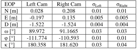
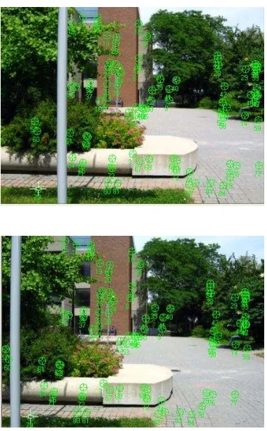
Self-calibration was performed in the field to compare the results with the laboratory calibration. A tripod was centred on a ground control point and the MSMS was mounted onto the tribrach adapter as seen in Figure 1. One image from each camera was taken simultaneously. 14 control points and 70 tie points were used; they are shown in Figure 3. The ground control points were automatically collected from a geo-referenced Lidar point cloud, (Figure 4), using the method described in Li-Chee-Ming and Armenakis (2010a). The control points are accurate to 2 centimetres. The estimated EOPs are expressed in a local north-east-down (NED) coordinate system. The coordinate system’s origin is the ground control point that the tripod was centred on. The EOPs for the left and right cameras are given in Table 1.
EOP Left Cam Right Cam σLeft σRight
N [m] 0.028 0.208 0.01 0.01
E [m] -0.197 0.135 0.005 0.005
D [m] -1.522 -1.524 0.004 0.004
ω [°] 89.972 91.1665 0.03 0.03 φ [°] -111.774 -110.593 0.01 0.01 κ [°] 180.358 181.620 0.03 0.04
Table 1. Estimated exterior orientation
The results of both calibrations are shown in Table 2. The interior orientation parameters are consistent. However the lens distortion parameters could not be accurately estimated in the field calibration because the accuracy of the control network was not sufficient.
Field Calibration Laboratory Calibration
Table 2. Camera calibration results
Figure 3. Field calibration stereopair (top: left camera , bottom: right camera)
Following the camera calibration, a system calibration was performed to determine the leverarm from the GPS antenna to each camera’s perspective center, and the boresights between the IMU and the axes of each camera. This entailed the collection of GPS, IMU, and magnetometer observations as the images were captured.
2.2 Boresight Calibration
Boresight calibration determines the rotation matrix relating the vehicle’s body axes of the IMU to the axes of the camera, that is, it determines the rotation matrixR in Equation 2. Unlike the cb
leverarm calibration, it is not possible to directly measure the relative orientation parameters. The common method used to perform
Figure 4. Self-calibration target field
this calibration requires R and cM
mapping frame. R is determined using the roll, pitch, and yaw bM
from the IMU/magnetometer. The boresight R is then cb
calculated using Equation 2.
MThe attitudeR of the IMU with respect to the mapping frame bM
was estimated in a Kalman filter, where the IMU attitude state was expressed as a quaternion orientation (q0, q1, q2, q3) in the 3D mapping frame. The observation equations relating the unit quaternion components to the familiar Euler angles (ω, φ, κ) are given in Equation 3.
The angular state of the IMU (q0, q1, q2, q3) propagated in time is expressed by the quaternion derivative:
Attitude was estimated, using Equation 5 (Ozyagcilar, 2011), from accelerometer and magnetometer measurements collected as the images in Figure 3 were captured. The sensors were static during the entire calibration, thus the IMU biases were removed simply by subtracting the respective means from each
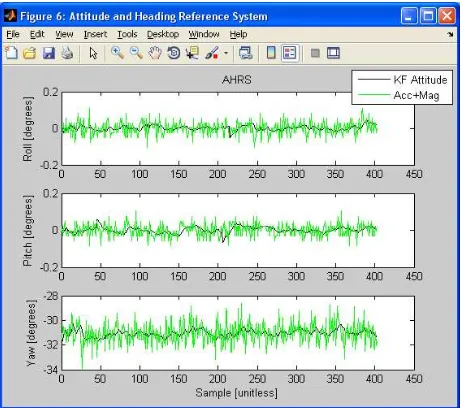
The estimated orientation is shown in Figure 5. The green series is the attitude from magnetometer and accelerometer data, the black series is the Kalman filtered orientation.
Figure 5. AHRS’ attitude estimation
The average roll (0.002° ±0.12°) and pitch (0.002° ±0.16°) are the angular misalignments between the IMU and the levelled tribrach. The average yaw is the magnetic heading (-31.039° ±0.26°). The geographic heading is found by adding the magnetic declination at that location (10.5° for ECEF). Thus the geographic heading is -20.54°.
The boresight Eulers angles are extracted from their respective rotation matrices and provided in Table 3.
b
Table 3. Boresight Euler angles
2.3 Leverarm Calibration
The leverarm from the GPS antenna to the perspective center of the camera, c to use the difference in the GPS antenna position determined by the GPS observations,rGPSM , and the simultaneous camera
while the images were taken. A GPS base station was setup and differential GPS processing was performed to accurately determine the position of the GPS antenna on the MSMS. Data was collected for 30 minutes, sampling at 1Hz. R and cM
M c
r were computed from the EOPs in Table 1. The leverarm in
the camera coordinate system was estimated and is provided in Table 4.
Table 4. Leverarm displacement vector in the camera frame
3. ACCURACY ASSESSMENT
To validate the calibration parameters, the object coordinates of check points were evaluated in terms of their standard deviations estimated from the bundle adjustment. The direct georeferencing accuracy was then assessed by evaluating the object coordinates accuracies obtained by space intersection of directly georeferenced images, without control points.
3.1 Check Point Accuracy
12 check points were used to assess the 3D positional accuracy of points estimated through the bundle adjustment. The points were spread throughout the image, as seen in Figure 6. The mapping coordinates of the points where previously determined through a topographic survey accurate to 1 centimetre and were not used in the bundle adjustment. The standard deviations of the object coordinates are given in Table 5. The differences between the known and estimated coordinates are given in Table 6. The accuracy is low compared to the accuracy of the EOPs. This is likely due to short baseline (37.8 centimetres) between the cameras. Further, only two measurements were used per point. Including more measurements will increase the accuracy.
ID σN (± m) σE (± m) σD (± m)
1 0.641 0.015 0.021
2 0.532 0.555 0.223
4 0.462 0.483 0.145
5 0.594 0.614 0.085
6 0.030 0.032 0.001
8 0.066 0.069 0.003
9 0.072 0.070 0.009
10 0.517 0.500 0.022
11 0.044 0.068 0.025
12 0.594 0.368 0.200
13 0.106 0.133 0.005
14 0.235 0.136 0.030
Mean 0.325 0.253 0.064
Table 5. Standard deviations of the extracted points
ID ΔN (m) ΔE (m) ΔD (m)
1 0.197 -0.048 -0.011
2 0.261 0.297 0.068
4 -0.039 -0.017 -0.019
5 0.492 0.508 0.063
6 -0.242 -0.231 -0.024
8 -0.160 -0.157 -0.003
9 0.537 0.541 -0.065
10 0.370 0.364 0.013
11 0.275 0.380 0.085
12 0.708 0.610 0.143
13 0.085 0.102 -0.014
14 0.636 0.435 -0.064
Mean 0.260 0.232 0.014
StDev 0.307 0.290 0.063
Table 6. Coordinate differences at check points
Figure 6. Check points
3.2 Direct Georeferencing Accuracy
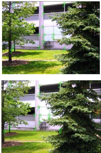
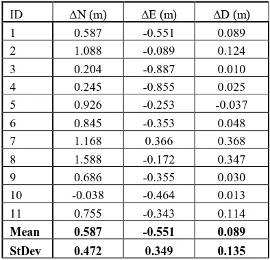
A second dataset was collected to evaluate the 3D positional accuracy of points extracted from a directly georeferenced stereopair (Figure 7). Two images were simultaneously collected by the MSMS mounted on a tripod. The images were directly georeferenced using the calibration parameters (IOPs, leverarms and boresights) from the described system calibration, along with GPS, IMU, and magnetometer measurements collected as the images were captured. No ground control was used. 11 points were extracted from the images; this is also shown in Figure 7. These points were previously surveyed to 1 centimetre via total station. Space intersection was performed to estimate the mapping coordinates of these points and compare them with the known values. The posterior standard deviations are given in Table 7. The differences between the known and estimated coordinates are given in Table 8. The mapping accuracy can be increased by including more information such as more images, ground control, epipolar geometry constraints, and optimal baseline lengths. These considerations will be investigated in further work.
Figure 7. Directly geoferenced stereopair and check points
(top: left camera , bottom: right camera) ID σN (± m) σE (± m) σD (± m)
1 1.387 1.311 0.559
2 1.320 1.249 0.403
3 1.711 1.603 0.238
4 0.954 0.919 0.038
5 1.176 1.126 0.057
6 1.289 1.140 0.153
7 1.729 1.516 0.076
8 0.507 0.703 0.273
9 1.910 1.057 0.629
10 0.839 0.953 0.038
11 0.145 0.075 0.018
Mean 1.179 1.059 0.226
Table 7. Standard deviations of the extracted points
ID ΔN (m) ΔE (m) ΔD (m)
1 0.587 -0.551 0.089
2 1.088 -0.089 0.124
3 0.204 -0.887 0.010
4 0.245 -0.855 0.025
5 0.926 -0.253 -0.037
6 0.845 -0.353 0.048
7 1.168 0.366 0.368
8 1.588 -0.172 0.347
9 0.686 -0.355 0.030
10 -0.038 -0.464 0.013
11 0.755 -0.343 0.114
Mean 0.587 -0.551 0.089
StDev 0.472 0.349 0.135
Table 8. Coordinate differences at check points
4. CONCLUDING REMARKS
A low-cost light weight mobile stereo-mapping system (MSMS) has been developed and calibrated for providing navigation and 3D geo-spatial data from UAVs. Direct georeferencing is used for the two cameras, with no external information, such as ground control, except for the GPS base station used in the RTK solution. Navigation is based on single frequency differential GPS, loosely coupled with a low-cost digital compass and MEMS IMU. The navigation system autonomously provides position, velocity, and attitude of both cameras in a mapping reference frame. The methods and results of a rigorous calibration process to determine systematic errors and biases of the MEMS sensors and to determine the sensors relative geometry have been presented. Camera, boresight and leverarm calibration processes have been performed. An overall accuracy assessment of the calibrated system was performed using a 3D test field. The encouraging results indicate that the system can be tested onboard unmanned aerial vehicle systems.
REFERENCES
Applanix (2011). Applanix POSAV airborne system, www.applainix.com (accessed 30-Sept-2011).
Canon Hack Development Kit (CHDK) User Quick Start Guide V.1.8.9, 2010.
El-Sheimy, N., 1996. The Development of VISAT - A Mobile Survey System For GIS Applications. Ph.D. Dissertation, University of Calgary, Department of Geomatics Engineering, Alberta, Canada.
Ellum, C. and N. El-Sheimy, 2002. The calibration of image-based mobile mapping systems. Proceedings of the 2nd Symposium on Geodesy for Geotechnical and Structural Engineering. May 21-24, Berlin, Germany. The International Association of Geodesy (IAG).
Li-Chee-Ming J., C. Armenakis, 2010 (a). Fusion of optical and terrestrial laser scanner data. CD-ROM proceedings Canadian Geomatics Conference 2010 and ISPRS Com I Symposium, Calgary, International Archives of the Photogrammetry, Remote Sensing and Spatial Information Sciences, Vol.XXXVIII Part 1.
Li-Chee Ming J., C. Armenakis, 2010 (b). Towards the development of a low-cost remotely-piloted land mobile mapping system. CD-ROM 2010 Annual Conference of the American Society for Photogrammetry and Remote Sensing.
Ozyagcilar, T., 2011. Implementing a tilt-compensated eCompass using accelerometer and magnetometer sensors. Freescale Semiconductor Application Note, Document Number AN424.
PhotoModeler (2011). PhotoModeler camera calibration, www.photomodeler.com (accessed 30-Sept-2011).
ACKNOWLEDGEMENTS
This research is financially supported by the Natural Sciences and Engineering Research Council of Canada (NSERC) and the Ontario Graduate Scholarship (OGS) program. The contributions of the graduate students Mark Post and Tom Yeung, Space Engineering, York University, in the hardware design of the platform are much appreciated.