A C C UR A C Y A S S E S S M E NT O F UND E R W A T E R PH O T OG R A M M E T R I C
T H R E E D I M E NS I ONA L M O D E L L I NG F O R C O R A L R E E F S
T . Guo
a,
*, A . C apra
b
, M. T royer
a
, A . Gruen
a
, A . J . B rooks
c
, J . L . Hench
d
, R . J . Schmitt
c
, S . J . Holbrook
c
, M. D ubbini
e
a
T heoretical Physics, E T H Z urich, 8093 Z urich, Switzerland - (taguo, troyer)@ phys.ethz.ch, agruen@ geod.baug.ethz.ch
b
D ept. of E ngineering “E nzo F errari”, University of M odena and R eggio E milia, via Pietro V ivarelli 10/1, 41125 Modena, Italy – alessandro.capra@ unimore.it
c
M arine S cience Institute, University of C alifornia, S anta B arbara. Santa B arbara, C alifornia 93106-6150, US A – ajbrooks@ ucsb.edu, ( schmitt, holbrook)@ lifesci.ucsb.edu
d
Nicholas S chool of the E nvironment, D uke University, B eaufort, NC , USA - jim.hench@ duke.edu
e
D ept. of History C ulture C ivilization – Headquarters of Geography, University of B ologna, via Guerrazzi 20, 40125 B ologna, Italy -marco.dubbini@ unibo.it
C ommission V , W G V /5
K E Y W OR D S : Photogrammetry, Underwater 3D Modelling, A ccuracy A ssessment, C alibration, Point C louds, C oral R eefs, C oral Growth, Moorea
A B S T R A C T :
R ecent advances in automation of photogrammetric 3D modelling software packages have stimulated interest in reconstructing highly accurate 3D object geometry in unconventional environments such as underwater utilizing simple and low-cost camera systems. T he accuracy of underwater 3D modelling is affected by more parameters than in single media cases. T his study is part of a larger project on 3D measurements of temporal change of coral cover in tropical waters. It compares the accuracies of 3D point clouds generated by using images acquired from a system camera mounted in an underwater housing and the popular GoPro cameras respectively. A precisely measured calibration frame was placed in the target scene in order to provide accurate control information and also quantify the errors of the modelling procedure. In addition, several objects ( cinder blocks) with various shapes were arranged in the air and underwater and 3D point clouds were generated by automated image matching. T hese were further used to examine the relative accuracy of the point cloud generation by comparing the point clouds of the individual objects with the objects measured by the system camera in air ( the best possible values). Given a working distance of about 1.5 m, the GoPro camera can achieve a relative accuracy of 1.3 mm in air and 2.0 mm in water. T he system camera achieved an accuracy of 1.8 mm in water, which meets our requirements for coral measurement in this system.
* C orresponding author
1. I NT R O D UC T I O N
T he Moorea Island D igital E cosystem A vatar ( ID E A ) project was recently developed as a joint initiative by an interdisciplinary group of experts to create a digital A vatar of the Pacific island of Moorea, F rench Polynesia ( C ressey, 2015, D avies 2016). T he major goal is to develop a unifying framework where ecological data and social information are assembled into a comprehensive time-evolving model of the island - an A vatar that would allow scientists to generate and test hypotheses about the impact of natural and man-made activities (http://mooreaidea.org/) .
Moorea has attracted the interests of biologists, ecologists and environmentalists due to its strategic location in the middle of the South Pacific Ocean, where its surrounding coral reefs, offering some of the most complex ecosystems on earth, can be studied to reveal the effects of natural and anthropogenic. T he precise 3D measurement of coral and its change over time will be an essential component of future investigation of impacts of climate change (e.g. ocean warming, increases in cyclones, ocean acidification). C hanges in amount of corals on reefs are typically measured through two-dimensional assessments of coral cover. However, this metric fails to capture changes
occurring in architectural complexity ( A lvare-F lilip et al., 2011) , and the importance of assessing this aspect has been increasingly recognized. R isk ( 1972) was among the first to report a strong positive correlation between fish species diversity and substrate topographic complexity, an observation that has been repeated for both abundance and species richness in a variety of coral reef systems including Moorea (Holbrook et al. 2002, 2003, Schmitt and Holbrook 2007). T his is an important ( albeit not the only) reason why the topography of coral habitats is so much of interest. A fter testing different, quite primitive methods of measuring coral topography ( McC ormick, 1994) the “chain–and-tape” method became a standard approach. T his method uses “rugosity” as a measure of coral topographic complexity (small scale variation of height differences). R ugosity is defined as fr = A r/A g, whereby A r is the real ( true) surface and A g is called the “geometric” surface area. T he chain-and-tape method measures only profiles in vertical planes. It uses a fine-link chain which follows the height variations and its length is compared with the length of its vertical projection onto a horizontal reference plane. A decisive step forward in methodology was introduced by D u Preez and T unnicliffe ( 2012) , who used a laser point profiler together with a single video camera to reconstruct height profiles from moving platforms like R OV s, scuba divers,
A UV s, or mounted on a trolley platform. T his micro-topographic laser scanning ( MiL S ) method follows the standard photogrammetric structured light principle. F riedman et al. ( 2012) further refined the technique, using a geo-referenced stereo camera system mounted on an R OV , A UV , manned submersible or diver-held platform and photogrammetric stereo processing principles to generate D igital S urface M odels. T raditional aerial and terrestrial photogrammetry has very successfully employed 3D modelling and the number of its applications in various disciplines has grown considerably in recent decades. In the field of underwater photogrammetry great efforts have been made in the areas of underwater archaeological surveys, marine biological investigations and offshore and other industrial inspection applications ( C apra, 1992). In particular, recent advances in both underwater photographic equipment and automation of photogrammetric 3D modelling software have triggered interest in building simple and low-cost solutions for reconstructing highly accurate 3D object geometry in underwater environments.
T he first underwater camera systems were developed by the F rench marine biologist L ouis B outan at the end of the nineteenth century (Nocerino et al., 2016) .Underwater photographic equipment remained complicated and costly, and thus limited to professional usage by experts until recently when consumer-grade compact digital cameras with waterproof housings became widely available. A mong a large number of off-the-shelf underwater cameras, the GoPro cameras with their waterproof dive cases are very popular because they are very small, compact, robust, and low-cost, with a high resolution still camera that has high definition video capability. C urrently GoPro cameras are increasingly used for underwater photogrammetry, including bathymetry measurement ( Schmidt et al., 2012), underwater archaeological surveys (C apra et al., 2015.
A dvances in software for automated processing and production of 3D models from image sequences greatly expand the usability of low-cost camera systems in photogrammetric applications, including underwater measurement and modelling. T raditional photogrammetric methods require manually controlled processing such as precise measurements of control/tie points for image orientation, camera calibration and geo-referencing processes, which normally leads to considerable effort and expense to process large blocks of images. A utomated processing techniques have seen considerable progress recently. Improvements in feature extraction and image matching have helped automation performance ( R emondino et al., 2008) speeding up processing even of very large blocks of images considerably (A garwal et al., 2011). M oreover, many low-cost commercial and open-source software packages for automated 3D modelling from images have been developed ( reviewed by R emondino et al., 2012) . T he accuracy of the high-resolution 3D model produced by such solutions is comparable to more expensive photogrammetric and L idar techniques (T hoeni et al., 2014; J avernick et al., 2014; R emondino et al., 2012) . T herefore it is very straightforward to adapt such techniques to underwater 3D modelling.
T here have been numerous recent publications reporting underwater 3D modelling in archaeological surveys, biological investigations and industrial inspection, and most of the generated 3D models are visually very impressive. F or the
applications of visualization, object-based navigation and other similar purposes, these 3D models are sufficient, but if accuracy and reliability matter, it is essential to precisely quantify 3D geometry. However, to date the accuracy issue of underwater 3D modelling has not been adequately addressed. F or example, in the M oorea ID E A project (C ressey 2015, D avies 2016) an important task is to detect the changes of corals in 3D over time in order to monitor the growth of coral colonies and their responses to environmental changes.. A ccording to a previous study ( B essat et al., 2001) the average annual growth rate of coral in Moorea is about 11-14 mm. T his means that our 3D coral model accuracy should be on mm level.
A ssessment of accuracy of underwater 3D modelling is challenging, because the precise measurement of Ground C ontrol Points ( GC Ps) and check points underwater is difficult. B oth the properties of water and camera influence image formation, by altering the path of optical rays ( Nocerino et al., 2016). S pecifically, the camera model is quite different underwater compared to air. Mathematical models have been presented that address the refraction problems ( Maas 2015; A grafiotis et al. 2015) .
.
In order to conduct a successful underwater photogrammetric project, minimization of the effects from the potential error sources at every stage is crucial. It is important to understand what factors influence the underwater photography and the processing functions of 3D modelling. F irst of all, the properties of water need to be considered. T he density of water is nearly 800 times that of air, and is also not constant, being a function of temperature, salinity and pressure, all of which can be correlated (Nocerino et al., 2016). T his results in strong variability of the refractive index for seawater. Illumination conditions underwater are also very complicated. A great amount of the sunlight radiation is reflected on the surface and absorbed, and the different components of light in different wavelengths are absorbed differently so that it makes the underwater environment appear bluish and greenish. Moreover, turbidity, scattering, and backscattering of the external light sources lead to poor illumination conditions underwater. T his may lead to blurred images that could affect feature identification and automatic extraction, as well as produce poor quality texture at the data processing stage. L ast but not least, the characteristics of underwater photographic equipment are also critical. T he geometric and optic characteristics of the lens port such as the shape (flat and dome) , the volume of the port space, and even the alignment of the port with the lens affect the geometric quality of the images (Nocerino et al., 2016). Good calibration of the underwater camera system is fundamental to ensure the accurate and reliable measurement of 3D objects. T he conventional approach is to carry out the calibration in a suitable environment beforehand, such as in a swimming pool. However, the difference between the calibration environment and the actual working environment in the sea can be substantial. Instead of such off-line calibration we prefer in-situ calibration, which involves placing the calibration devices in the actual environment, and simultaneously acquiring the objects and calibration information embedded in the same images in order to minimize influences from the environment and to improve the accuracy of 3D models as much as possible.
T he objective of this study was to develop a method for assessing the accuracy of a low-cost underwater
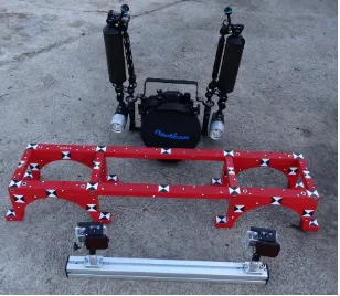
photogrammetric 3D modelling solution, which consists of an off-the-shelf underwater consumer-grade camera system and automated 3D modelling software tools. F urthermore, we show an in-situ calibration method to ensure the accurate and reliable measurements of corals in 3D . F or this we use a precisely surveyed 3D reference frame, which we put into the scene (both in air and underwater) and applied self-calibration. In addition, we also put cinder blocks, which have a similar surface roughness as some corals, into the scene. W e do not have reference data on the cinder blocks. T herefore we determined their 3D models with the L umix camera in air ( which gave us the best possible values) and used these models as reference for all other investigations. T he accuracies, which are in the mm-comprise the cameras with lenses, waterproof housings with lens ports, and a calibration frame ( F igure 1) . T o investigate the performance of different types of consumer-grade camera systems, two cameras mounted with waterproof lens ports as Pixel size 1.55 microns 3.74 microns Housing/port F lat plastic
case
Nauticam NA -GH4 with Nauticam 180mm optical glass wide angle dome port T able 1. Underwater cameras used in this study.
T he GoPro Hero4 is a popular, low cost and high resolution camera, and comes with a waterproof dive case with flat port that is capable of withstanding depths up to 40 meters. T he L umix GH4 is a mirrorless system camera used with an M.Z uiko E D 12-40mm f2.8 PR O lens in a waterproof Nauticam NA -GH4 housing with a Nauticam 180mm optical glass wide angle dome port , which makes the light rays enter the spherical dome port almost perpendicularly to the dome port and go to surface to the working area, where the depth is up to about 15m is within a range of 3-5°C , which produces a potential
( maximum) length variation of about 35 micron for the 1 m length of the bar. T his geometric variation is far less than the accuracy requirements at some mm level for coral reefs measurement, and therefore the calibration frame is capable of providing very reliable control information in underwater environments.
F igure 1. C alibration frame with camera systems L umix GH4 and the GoPro Hero4 stereo camera bar
2.2 C amer a systems calibr ation in air and underwater W e utilized the A gisoft PhotoS can package in this study. PhotoS can provides automatic image orientation, camera calibration, dense 3D point cloud generation, 3D mesh construction, and texture mapping from large datasets of overlapping image sequences. C ontrol and reference information can be manually annotated, and then used to optimize image orientation, camera calibration and coordinate system referencing. PhotoS can uses the B rown approach for camera and target arrays are three dimensional in nature; ( 2) the different convergent camera views approach a 90 degree intersection at the centre of the target array; ( 3) the calibration fixture or range fills the field of view of the camera( s) to ensure that image measurements are captured across the entire format; and ( 4) the camera(s) are rolled around the optical axis for different exposures so that 0, 90, 180 and 270 degree orthogonal rotations are spread throughout the calibration network ( S hortis, 2015) .
In practice, it is difficult to meet all of these criteria. T he compact calibration fixture is very easy to transport and used in various environments. In particular, for in-situ calibration underwater, a calibration fixture has to be mobile in order to be set up easily at different working sites. In this study, it was not always possible to fill the full format of images while measuring coral reefs by “flying” over at 1-1.5 meter working distance. In
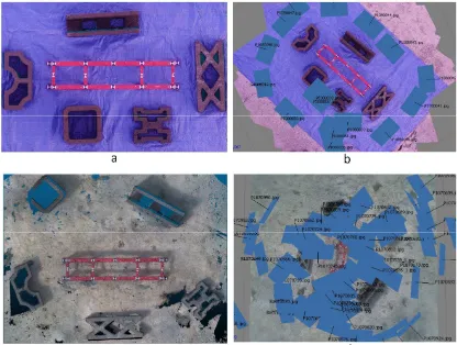
arrangement of the these cinder blocks both in air and underwater to compare the geometric variations of the 3D models generated in different cases, and to investigate the accuracy consistency in the area next to the calibration frame ( F igure 2).
F igure 2. C amera systems calibration settings in air and underwater. (a) 3D point cloud of calibration site in air. ( b) Image network in air. (c) 3D point cloud of calibration site
underwater. ( d) Image network underwater.
F igure 2 shows both calibration sites in air and underwater. T he cameras were used to take images at a working distance of about 1.5 meter in air and underwater. F igure 2(d) shows that it was not easy for a diver to shoot images evenly distributed covering the objects in the underwater environment, thus there are gaps in the 3D point clouds ( F igure 2c). T he measurements of the markers of the calibration frame were done manually in single image mode, while the cinder blocks were measured fully automatically, producing very dense point clouds. T he results of self-calibration are shown in T able 2.
T able 2. C alibration results of camera systems in air and underwater. f is the focal length; cx and cy are the principal point offsets; k1, k2, and k3 are symmetric radial distortion coefficients; b1 and b2 are affinity and non-orthogonality
( skew) coefficients; p1 and p2 are decentering distortion coefficients (A gisoft PhotoS can User Manual). T he calibration results show a large variation with the GoPro camera system both in air and underwater. T he change is expected as the flat waterproof case has less geometric accuracy and more refractive influence than does the dome housing. In
particular, the symmetric radial distortion increases at the borders of the flat lens case. F igure 3 shows the distortion maps of each camera in air and underwater. T he L umix system has an offset to the principle point, but less radial distortion, than the GoPro, which has a small fish eye type lens, resulting in significant radial distortion towards image borders, especially underwater.
F igure 3. D istortion maps of camera systems. T he red circle is the initial principle point, and the blue one is the calibrated principle point. (a) L umix in air, (b) L umix underwater, (c)
GoPro in air, ( d) GoPro underwater. 2.3 A ccur acy assessment of 3D point clouds
T here are 45 highly accurate reference points on our 3D calibration frame. Of these 12 evenly distributed points were selected for the self-calibration procedure and the other points were treated as check points for accuracy assessment. T he R MSE between the computed coordinates and the known coordinates of check points were calculated ( T able 3). T he results were quite encouraging. E ven though the accuracy of the GoPro was degraded about 0.25 mm compared to the L umix, the GoPro was still able to achieve an accuracy of about 0.5 mm underwater, which meets our requirements for coral measurement. In an additional effort we investigated the accuracy consistency of objects in the space next to 3D calibration frame.
A ccuracy L umix GoPro
A ir Underwater A ir Underwater
R MSE (mm) 0.12 0.15 0.36 0.40
T able 3. A ccuracy ( R MS E ) of camera systems in air and underwater computed from 33 check points at the reference
frame.
F irstly, for the calibration site in air, by using the open source software C loudC ompare (www.danielgm.net) , we were able to compare the 3D point clouds of the full scene generated using images from L umix and GoPro camera systems (F igure 4 and T able 4). T he difference between the two 3D point clouds is quite small. L arger variations are observed on the blue plastic sheet at the background (see the red portions of the error surface), because the surface shape of the plastic sheet was changing during image acquisition due to wind.
C alibration Parameters
L umix ( f=12mm) GoPro (f=2.98mm)
A ir UW A ir UW
f ( mm) 12.58 12.632 2.69 3.65
cx (pix) -43.49 -35.64 -9.41 -5.88
cy (pix) -82.03 --83.84 53.40 40.66
k1 -0.0174 -0.0361 0.0668 0.2324
k2 0.0066 0.0515 -0.0076 0.0714
k3 0.0058 -0.0427 0.0120 0.3948
b1 -0.4397 0.5567 -1.8301 0.4647
b2 1.6674 1.1622 -0.2945 -0.3143
p1 -0.0045 -0.0034 -0.0008 -0.0006
p2 -0.0035 -0.0031 0.0005 -0.0002
F igure 4. C omparison of 3D point clouds from L umix and GoPro camera systems of calibration scene in air. T he same comparison was also conducted for the calibration site underwater as shown in F igure 5 and T able 4. T he results are quite similar. T he variation comes mainly from different coverage of the background ( in air we have a blue plastic sheet, under water we have sand) .
F igure 5. C omparison of 3D point clouds from L umix and GoPro camera systems of calibration scene underwater.
T able 4. D ifference between 3D point clouds from L umix and GoPro camera systems of calibration scenes in air and
underwater.
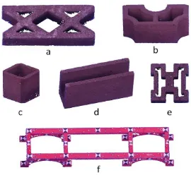
In order to mitigate the influence of the background in the comparison of the 3D point clouds, a comparison of the 3D point clouds of each object ( cinder block) was also conducted. C onsidering the good geometric and optical characteristics and the accuracy as shown in F igure 3 and T able 3, 3D point clouds generated by using L umix in air were relatively precise. T herefore, the 3D point clouds of five cinder blocks and the calibration frame were extracted from the 3D scene generated by using L umix in air ( F igure 6) . Since the intensive editing has been done in the extraction processing, they were matched back to the original 3D point cloud of the calibration scene to check the accuracy/correctness to their original shapes. T his resulted in a relative R MS E of 0.13 mm for 3D geometric variation.
T hese 3D point clouds of objects were further utilized as the reference in the following object comparison.
F igure 6. 3D point clouds of objects ( a-e are cinder blocks) extracted from the 3D scene generated by using the L umix camera system in air. T he 3D point cloud of each reference
object was compared to its counterpart in other 3D scenes respectively. T he comparison results are as shown in F igure 7
and the R M SE s are shown in T able 5.
F igure 7. C omparison of 3D objects. (a) GoPro in air to L umix in air (b) L umix underwater to L umix in air ( c) GoPro
underwater to L umix in air 3D point
clouds
A ir Underwater
GoPro L umix GoPro
R MS E ( mm) 1.34 1.82 1.97
T able 5. A ccuracy comparison of 3D point clouds generated using L umix and GoPro camera systems in air and underwater.
3. C ONC L US I O NS
A s a part of the Moorea Island D igital E cosystem A vatar ( ID E A ) project (http://mooreaidea.org/), this study aimed to develop a low-cost and high-efficiency approach for assessing the growth of coral reefs over time in detail in 3D space, which provides valuable data and metrics to quantify changes and trends in reef ecosystems. B ecause the average annual growth rate of coral in Moorea is about 11-14 mm, it requires that the solution is able to provide 3D measurement at mm level accuracy underwater.
T he combination of off-the-shelf underwater consumer-grade camera systems and automated 3D modelling software tools have made it possible to apply photogrammetric 3D modelling methods in underwater environments in an economical and efficient way. However, the accuracy assessment issue of underwater 3D modelling is quite challenging, because the precise measurement of GC Ps and check points in the unconventional environment of underwater is difficult, and water body--lens port--air in waterproof lens housings form a complicated multiple media environment that greatly alters the path of optical rays. Moreover, physical factors in the 3D D iff. of
point clouds
Max ( mm) Mean ( mm) R MS E ( mm)
A ir 10 1.8 3.22
Underwater 12 1.6 5.41
underwater photogrammetry environment can vary strongly with depth and rapidly over time.
C alibration of underwater camera systems is fundamental to ensuring the accurate and reliable measurements of 3D objects. Instead of the conventional way, which carries out the calibration beforehand, we applied an in-situ calibration method by placing a calibration frame in the actual working environment to minimize the influence from environmental factors and improve the accuracy of 3D models as much as possible. W e compared two underwater camera systems – a GoPro camera with a flat waterproof case, and a L umix GH4 system camera with a hemispherical dome port. T he self-calibration results suffer due to the fact that the software we used ( A gisoft PhotoS can) did not deliver a statistical analysis of the self-calibration parameters (e.g. the covariance matrix). T herefore, the stability and significance of individual parameters could not be checked. B ut it was found that, due to the dome port of the L umix camera, the correction parameters are much smaller than for the GoPro camera with flat port housing.
T he 3D measurement accuracies of both underwater camera systems are quite encouraging. T hough the accuracy was degraded about 0.25 mm comparing to L umix, GoPro was still able to achieve the accuracy of about 0.5 mm underwater, which meets our requirements for coral measurement in this study. W e further examined the relative accuracy of the point cloud generation by comparing the point clouds of the individual objects with the objects measured by the system camera in air
( the best possible values). Given a working distance of about 1.5 m, the relative accuracy of 3D point clouds generated by the L umix camera system underwater was about 1.82 mm, while GoPro in air was about 1.34 mm, and underwater about 1.97 mm. T he results show both underwater camera systems are able to meet the 3D modelling accuracy requirements for coral measurements. It must be emphasized that these accuracy values have been computed by comparing the point clouds of the individual objects with the corresponding ones generated with the L umix camera in air. T hey are not based on comparisons with independent reference values.
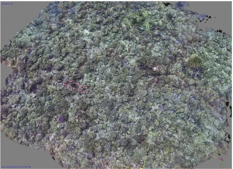
F igure 8 shows the 3D point cloud of a 5m x 5m coral reef patch generated using images from a GoPro underwater system. T he calibration frame is clearly visible, as is a band that marks the border of the patch and serves as a visual reference for the diver for spatial orientation during image acquisition.
F igure 9. B lue band shift towards image border F igure 8. 3D point clouds of a 5m x 5m coral reef patch generated using images from a GoPro underwater system.
T he accuracy of the camera calibration and 3D point cloud generation is strongly affected by both the image quality and the geometry and redundancy of calibration image network. T herefore, it is essential to plan and ensure an optimal image network. W e also note that the flat case of lens caused the different refraction shifts to different wavelengths towards the image border as shown in F igure 9, which caused image blur environmental disturbances and their rates of re-growth of coral. . complexity on C aribbean reefs. E cological Applications, 21(6) , pp.2223-2231.
B essat, F ., and B uigues, D ., 2001. T wo centuries of variation in coral growth in a massive P orites colony from M oorea (F rench Polynesia): a response of ocean-atmosphere variability from south central Pacific. Palaeogeogr. Palaeoclim. Palaeoecol., 175(2001), pp.381-392.
B rown, D .C ., 1971. C lose-range camera calibration. Photogr. E ng. V ol. 37, pp.855-866.
B urns, J .H.R ., D elparte, D ., Gates, R .D., and T akabayashi, M ., 2015. Utilizing underwater three-dimensional modelling to enhance ecological and biological studies of coral reefs. In: The
International Archives of the P hotogrammetry, Remote Sensing and Spatial Information Sciences, Piano di S orrento, Italy. V ol. X L -5/W 5, pp. 61-66. archaeological site: comparison between low cost cameras. In: T he International Archives of the Photogrammetry, Remote Sensing and Spatial Information Sciences, Piano di Sorrento, Italy. V ol. X L -5/W 5, pp. 67-72.
C ressey, D ., 2015. T ropical paradise inspires virtual ecology lab. Nature, V ol.517 ( 15 J an.2015), pp.255-256.
D avies, N., F ield, D ., Gavaghan, D . Holbrook, S.J ., Planes, S ., small-scale seafloor bottom roughness. L imnology and Oceanography: Methods. 10:899-909. [ D OI and F reshwater Research V ol. 53, pp. 181-188.
Holbrook, S.J ., B rooks, A .J ., and S chmitt, R .J ., 2003. V ariation in structural attributes of patch-forming corals and patterns of abundance of associated fishes. Marine and F reshwater Research V ol. 53, pp. 1045-1053.
ID E A project, http://mooreaidea.org/
J avernick, L ., J . B rasington, and B . C aruso., 2014. M odelling the topography of shallow braided rivers using S tructure-from-M otion photogrammetry. Geomorphology, V ol.213, pp.166-182.
M aas, H.-G., 2015. A modular geometric model for underwater photogrammetry. In: The International Archives of the P hotogrammetry, Remote Sensing and Spatial Information Sciences, Piano di S orrento, Italy. V ol. X L -5/W 5, pp. 139-141. M cC ormick, M.I., 1994. C omparison of field methods for measuring surface topography and their associations with a tropical reef fish assemblage. Marine E cology Progress Series, V ol. 112:87-96
M oorea C oral R eef ( MC R ) L ong T erm E cological R esearch ( L T E R ) , http://mcr.lternet.edu/
Nocerino, E ., Menna, F ., F assi, F ., and R emondino, F ., 2016. Underwater calibration of dome port pressure housings. In: The International Archives of the Photogrammetry, Remote Sensing and Spatial Information Sciences, L ausanne, Switzerland, V ol. X L -3/W 4, pp. 127-134.
R emondino, F ., E l-Hakim, S.F ., Gruen, A ., and Z hang, L ., 2008. T urning images into 3-D models. IE E E Signal P rocessing Magazine, V ol. 25, No. 4, J uly 2008, pp. 55-64
R emondino, F ., Pizzo, S.D ., K ersten, T .P., and T roisi, S ., 2012. L ow-cost and open-source solutions for automated image orientation – a critical overview. In E uroMed 2012, L NC S, V ol.7616, pp.40-54
R isk, M.J ., 1972. F ish diversity on a coral reef in the V irgin Islands. Atoll Res. Bull. 193:1-6 [ doi:10.5479/si.00775630. 153.1] .
S chmidt, V .E ., R zhanov, Y ., 2012. Measurement of micro-bathymetry with a GOPR O underwater stereo camera pair. In P roceedings of Oceans, Hampton R oad, V A , US A , 14–19 October 2012, pp. 1–6.
S chmitt, R .J ., and Holbrook, S.J ., 2007. T he scale and cause of spatial heterogeneity in the strength of temporal density dependence. E cology V ol. 88, pp.1241-1249.
S hortis, M., 2015. C alibration techniques for accurate measurements by underwater camera systems. Sensors, V ol.15( 12), pp. 30810-30826.
T hoeni, K ., Giacomini, A ., Murtagh, R . and K niest, E . 2014. A comparison of multi-view 3D reconstruction of a rock wall using several cameras and a laser scanner. In: The International Archives of the Photogrammetry, Remote Sensing and Spatial Information Sciences, R iva del Garda, Italy, V ol. X L -5, pp. 573-580.