VERIFICATION OF IMAGE BASED AUGMENTED REALITY
FOR URBAN VISUALIZATION
Takashi. Fuse a, *, Shoya Nishikawa a, Yuki Fukunishi a
a
Dept. of Civil Engineering, University of Tokyo, Hongo 7-3-1, Bunkyo-ku, Tokyo, 113-8656, Japan, - [email protected]
Commission IV, WG IV/4
KEY WORDS: Augmented Reality, Visualization, Urban, Close Range, Robotics, Navigation
ABSTRACT:
Recently, visualization of urban scenes with various information attracts attention. For the transmission of urban scenes, virtual reality has been widely used. Since the virtual reality requires comprehensive and detailed three dimensional models, the manual dependent modelling takes a lot of time and effort. On the other hand, it has been tackled that various data is superimposed on the scene which the users see at the time instead of comprehensive modelling, which is well known as augmented reality (AR). Simultaneous localization and mapping (SLAM) has been attempted using simple video cameras for the AR. This method estimates exterior orientation factors of the camera, and three dimensional reconstructions of feature points simultaneously. The method, however, has been applied to only small indoor space. This paper investigates the applicability of the popular method of SALM to wide outdoor space, and improves the stability of the method. Through the application, the tracked feature points successfully are greatly reduced compared with application in indoor environment. According to the experimental result, simple markers or GPS are introduced as auxiliary information. The markers gives the stability of optimization, and GPS gives real scale to AR spaces. Additionally, feature points tracking method is modified by assigning amplitude of displacement and depth. The effect of the markers and GPS are confirmed. On the other hand, some limitations of the method are understood. As a result, more impressive visualization will be accomplished.
1. INTRODUCTION
Recently, visualization of urban scenes with various information attracts attention from the perspective of landscape simulation, robot navigation and so on. For the transmission of urban scenes, virtual reality has been widely used. Since the virtual reality requires comprehensive and detailed three dimensional models, the manual dependent modelling takes a lot of time and effort. On the other hand, it has been attempted that various data is superimposed on the scene which the users see at the time instead of comprehensive modelling. The technique is well known as augmented reality (AR).
The AR uses sequential images taken from same view points of users as environmental scene, and then reality of visualization increase compared with the virtual reality. So far, a popular application of AR is tags superimposition on sequential images based on GPS and electronic compass. The application cannot superimpose three dimensional models such as CAD, CG, or so on, because of less accurate exterior orientation factors of the platforms. To employ such three dimensional models in the AR, expensive magnetic field sensors are installed in the environment. The system comes to large scale, and so the applicability is restrictive.
Against the above problem, simultaneous localization and mapping (SLAM) has been developed using simple video cameras. This method estimates exterior orientation factors of the camera, and three dimensional reconstructions of feature points simultaneously. The method, however, has been applied to only small indoor space.
This paper investigates the applicability of the method to wide outdoor space, and improves the stability of the method.
2. SIMULTANEOUS LOCALIZATION AND MAPPING
SLAM has been developed initially in the field of robotics. The SLAM problems arise when the robot does not have access to a map of the environment, nor does it know its own pose. Against the problem, in SLAM, the robot acquires a map of its environment while simultaneously localizing itself relative to this map (Thrun et al., 2006).
There are two main forms of the SLAM. One is known as the online SLAM: it involves estimating the posterior probability over the momentary pose along with the map. Many algorithms for the online SLAM are incremental, specifically they discard past measurements once they have been processed. Another is known as the full SLAM. In full SLAM, we seek to calculate a posterior probability over the entire path along with the map, instead of just the current pose. Assuming the probability distribution is the normal distribution, the estimation of the posterior probability becomes least squares method. In the sense of bundle adjustment in photogrammetry, online and full SLAM are correspond to recursive (or local) and global bundle adjustment, respectively. In the field of robotics, real time processing is required. Practically, online SLAM has been widely used in the field.
There are two popular techniques for online SLAM: EKF SLAM and FastSLAM. The EKF SLAM algorithm is based on
Extended Kalman Filter (Smith and Cheeseman, 1986) using maximum likelihood data association. The EKF SLAM is subject to a number of approximations and limiting assumptions. Maps are feature-based, which are composed of point landmarks. For computational reasons, the number of the point is usually small. The EKF SLAM is strongly influenced by the detection of the point landmarks.
FastSLAM (A Factored Solution to the SLAM) algorithm apples particle filter to online SLAM (Montemerlo et al., 2002). The particle filter is a method as a stochastic process, integrating observations and state transition on the framework of general state space model (Isard and Blake, 1998; Doucet et al., 2000). Advantage of the FastSLAM is efficiency of the computational load compared with the EKF SLAM. More important advantage is the following. EKF SLAM can basically deal with normal probability distribution. On the other hand, FastSLAM (or particle filter) can deal with arbitrary probability distribution and nonlinear model.
Augmented reality community has also attempted to deal with the SLAM problem. One of the most popular methods among SLAM in the field is Parallel Tracking and Mapping (PTAM) (Klein and Murray 2007). It consists of exterior orientation based on feature points extraction and tracking in a sequential image (tracking process), and three dimensional coordinates estimation of the feature points (mapping process). The method performs the above two processes in parallel threads on dual-outline of the method and its applicability.
3. APPLICABILITY OF SLAM
3.1 Outline of the SLAM Method
The outline of the method is summarized by the following points (Klein and Murray 2007):
(a) Tracking and mapping are separated;
(b) Mapping is based on key frames, which are processed using batch techniques (bundle adjustment);
(c) The map is densely initialized from a stereo pair; (d) New points are initialized with an epipolar search; (e) Large numbers of points are mapped.
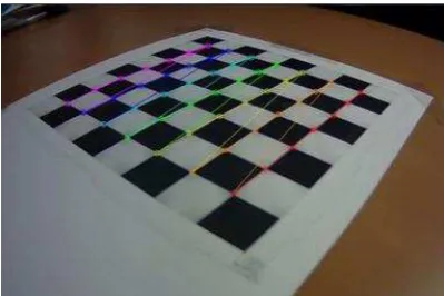
3.1.1 Camera Tracking: Camera calibration is conducted in
advance. For the calibration, checkerboard is used (Figure 1). Segment Test) corner detector (Rosten and Drummond, 2006) is utilized. The FAST corner detector recognizes corners, when the pixel value of the centre of image patch is brighter than ones of contiguous pixels.
The map has N key frames which are snapshots of a sequential image. The key frame has a three dimensional coordinates
qj = (Xj, Yj, Zj) as the camera position. At the key frames j, the feature point i has camera coordinates system (uij, vij). A
transformation matrix Eij between the camera coordinates and the world coordinates systems represents collinearity equation.
, = factors of interior orientation
akl = factors of rotation matrix
The key frames are also converted to image pyramid.
Figure 1. Camera calibration by using checkerboard
The camera tracking process (estimation of camera position and pose) performs the following two-stage tracking:
(a) A new frame is acquired from a camera;
(b) Initial position and pose of the camera are estimated by camera transition model;
(c) Feature points in the map are projected into the image according to the frame’s prior position and pose estimations, which have transformation matrix between the world coordinates and the camera coordinates including interior orientation factors;
(d) A small number of the coarsest-scale features are searched for in the image;
(e) The camera position and pose are updated from these coarse matches;
(f) A larger number of points is re-projected and searched for in the image;
(g) A final position and pose estimates for the frame are computed from all the matches found.
In order to search corresponding feature points between frames, affine warp characterized by a warping matrix A is used.
correspond to pixel displacements in the current camera frame’s full-seize pyramid level. The determinant of the warping matrix can decide the level of the image pyramid.
The position and pose updates are computed iteratively by minimizing a robust objective function of the re-projection error.
Tukey bi-weight objective function
T
Obj,
is applied as a robust objective function and x is a set of parameters. Iteration of reweighted least squares method is used to allow the M-estimator to converge.3.1.2 Feature Points Mapping: Once camera position and
pose are estimated, three dimensional coordinates of the feature points are mapped. First of all, an initial map is built based on intersection (Stewenius et al., 2006). For the optimization of intersection, RANSAC algorithm (Fischler and Bolles, 1981) is applied. Here, the scale and coordinate systems are arbitrary, not set as real scale and world coordinates.
After that, the map continuously refined and expanded, while key frames are added by the above camera tracking. The key frames are recognized when number of frames exceeds a certain frames from previous key frame. With the added key frames, the bundle adjustment is applied for improving the accuracy (Triggs et al., 2000). In order to solve the bundle adjustment problem, Levenberg-Marquardt method (Hartley and Zisserman, 2004) is applied. The objective function E is approximated by the following formula adjustment uses only some recent key frames. The full bundle adjustment is more accurate than the local bundle adjustment,
but computational load is more expensive. The local bundle adjustment method will be discussed later.
3.2 Investigation of the SLAM Applicability in Outdoor
Environment
We investigated the applicability in outdoor environment by comparing the feature points tracking in indoor and outdoor environments. Table 1 shows comparison of the results of feature points tracking during one minute.
Table 1. Comparison of the results of feature points tracking indoor outdoor initial number of feature points 1036 299
number of feature points in image pyramid level
0 (fine) 600-840 150-250
1 40-300 0
2 15-70 0
3 (coarse) 5-50 0
final number of feature points 2650 289
number of key frames 14 26
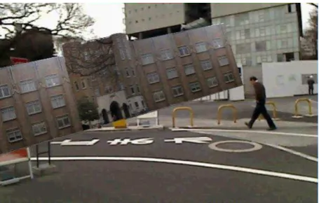
The tracked feature points successfully were greatly reduced compared with application in indoor environment. Since objects in the scene were very far, feature points extraction provided worse performance. Additionally, images features for tracking changed drastically with tiny camera moving. As a result, the estimated coordinate system tilted and three dimensional models arranged inappropriately (Figure 2).
Figure 2. Inappropriately model arrangement
4. IMPROVEMENT OF SLAM METHOD
According to the experimental result, the method is improved by introducing auxiliary information. One is simple markers as the auxiliary information, another is GPS.
4.1 Marker-Based Approach
One of approaches for improvement of the method is introduction of simple markers on ground as auxiliary information. ARToolKit (Kato and Billinghurst, 1999) is a famous software library of marker-based approach. The marker-based approach calculates the real camera position and orientation relative to physical markers in real time. The marker is defined as two dimensional code patterns (Figure 3), and it makes recognition easier.
Figure 3. Example of marker
Table 2 shows the result of the method with markers. Recognizing the markers increased in extracted and tracked feature points successfully. Moreover, the ground plane was estimated with stable by the marker arrangement (Figure 4). The effect of the markers was confirmed.
Table 2. Result of feature points tracking with markers initial number of feature points 1027
number of feature points in image pyramid level
0 (fine) 500-750
1 150-230
2 25-50
3 (coarse) 0-1 final number of feature points 1027
Figure 4. Model arrangement with markers
On the other hand, some limitations of the method were understood. Because the baseline between adjacent video frames is quite short, it was difficult that accuracy of the exterior orientation and three dimensional coordinates estimation of the feature points increased.
4.2 Refinement of Feature Points Tracking
As previously discussed, feature points extraction and tracking are important for the final result. Recently, more sophisticated
feature points extraction algorithms have been developed. One of the most reliable algorithms is SURF (Speeded-UP Robust Features) (Bay et al., 2008). The SURF algorithm uses box filter, which approximates Hessian-Laplace detector, for making integration images. The integration image improves computational speed. Additionally, points included in a certain radius circle are added for calculation of norm, and then orientation is adopted with maximum norm. According to above mentioned feature, the SURF is robust against scaling and rotation. Finally, image is divided into 4 x 4 block, and then differences of features are represented as 64 dimension SURF features (Figure 5) by using those gradient and amplitude
dx,
dy,
dx,
dy
Figure 5. Concept of SURF
We compared stability of the FAST and the SURF in outdoor environment, and confirmed that results of the SURF are more robust than ones of FAST. According to the results, this paper employs SURF as feature points extraction algorithm.
Even if the SURF is applied to feature points extraction and matching, incorrect matching points are still exist. Additionally, feature points matching is refinement by using not only adjacent frames also sequential frames. Firstly, extracted feature points are searched in sequence between adjacent frames. After the matching process is conducted within a certain number of frames, position of feature points are re-projected into first frames. If the displacement between first and last position of the points is larger than a threshold, the feature points are discarded. With the result of the matching, three dimensional coordinates of the feature points can be calculated. If the depth of the points is larger than a threshold, the feature points are also discarded. Finally, the remaining points are accepted as feature points. Figure 6 shows an example of results of matching refinement.
Figure 6. Matching refinement with SURF
4.3 GPS Utilization
As above-mentioned, the method is difficult to estimate real scale in world coordinates. To deal with the problem, GPS as auxiliary information is utilized. For easy application, single point positioning of GPS is used here. Since low-end device cannot be expected to enough accurate positioning, relative position between the measurements is applied for scale correction. Specifically, relative orientation is applied based on the feature points matching result in the previous section, and then the baseline b is modified to B by using GPS data.
b b
Z Z Y Y X X
B t t t t t t
2
1 2 1 2
1
(7)
Where (Xt, Yt, Zt) is a GPS measurement at time t. For the sequential frames, above process is applied. With the frames, whose position is modified by GPS, the bundle adjustment is applied for improving the accuracy. In the sense of computation, the local bundle adjustment is more preferable at the expense of accuracy. The local bundle adjustment can be applied recursively (Mclauchlan, 2000).
1 : 1 1 :
1j E jEj
E (8)
E1:j expresses the objective function by using from 1st key frame to jth key frame. According to the recursive form, bundle adjustment can be conducted effectively. It is important to point out here that the accuracy depends on the number of key frames with the recursive form. We examined the relationships between number of key frames and computation time / sum of squared error (Figure 7). In this case, the sum of squared error does not decrease more than four key frames. On the other hand, the computation time monotonically increase. Figure 8 depicts the comparison between the trajectories of before and after adjustment. After bundle adjustment, perturbation of the trajectory is affected.
2 3 4 5
sum of squared error (pixels)
computation time (seconds)
# key frames
Figure 7. Relationships between number of key frames and computation time / sum of squared error
before adjustment after adjustment trajectory of camera
Figure 8. Trajectory with bundle adjustment
4.4 Application of the proposed method
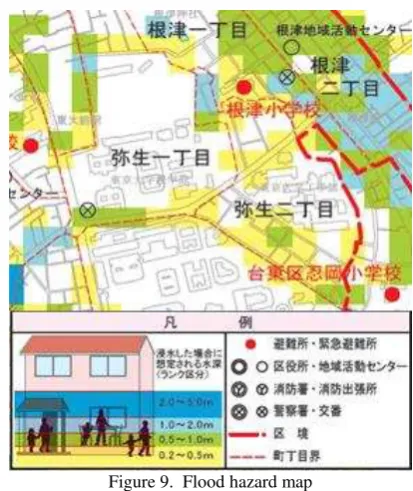
The proposed method was applied to images taken in urban area. The images were taken around a building with the resolution of 1280 x 720. The frame rate is 30 frames per second. In this application, we attempted to superimpose flooded height of a hazard map (Figure 9) onto the sequential image. The colour grids of the hazard map correspond to the flooded height (e.g. green represents 0.5-1.0m of flooded height).
Figure 9. Flood hazard map
Figure 10 shows an original image, a result of superimposition, and transition of the result (after one to three seconds). Compared with hazard map, it is realize that impression is improved with the real scene. Scale in world coordinate system can be kept in this application. The absolute position, however, decreases along with time.
5. CONCLUSIONS
This study verified the applicability of a popular method of SLAM to wide outdoor space. The method strongly depended on the feature points tracking. According to the verification, modification of feature points tracking and auxiliary information were introduced. We selected marker-based approach and GPS as the auxiliary information, and improved the stability of the method. In the application of GPS, we also studied effect of number of key frames for the local bundle adjustment. Through the application, the significance and limitation of the method were confirmed. Potential to various application of AR was implied.
As a further work, combination of model based method (Lepetit et al., 2003) will be investigated. When three dimensional models of large-scale structure are employed, parts of the models will be expected to contribute improvement of feature points tracking and reconstruction. Additionally, combination of sensor based method using IMU and so on, will become important issues. Finally, framework building of data fusion and sensor fusion will be required. As a result, more impressive visualization will be accomplished.
(a) original image
(b) superimpose hazard map
(c) superimposition after one second
(d) superimposition after three seconds
Figure 10. Superimpose hazard map onto sequential image
REFERENCES
Bay, H., Ess, A., Tuytelaars, T. and Vangool, L., 2008. Speeded-Up Robust Features (SURF). Computer Vision and
Image Understanding, 110(3), p.346-359.
Doucet, A., Freitas, N., Murphy, K. and Russell, S., 2000. Rao-Blackwellized particle filtering for dynamic Bayesian networks.
Proceedings of the 16th Conference on Uncertainty in Artificial Intelligence (UAI'00), pp176-183.
Fischler, M. and Bolles, R., 1981. Random sample consensus: A paradigm for model fitting with applications to image analysis and automated cartography. Communications of the ACM, 24(6), pp381-395.
Hartley, R. and Zisserman, A., 2004. Multiple View Geometry
in Computer Vision. Cambridge University Press, Cambridge.
Isard, M. and Blake, A., 1998. CODENSATION - Conditional density propagation for visual tracking. International Journal of Computer Vision, 29(1), p.5-28.
Klein, G. and Murray, D., 2007. Parallel Tracking and Mapping for Small AR Workspaces. Proceedings of 6th IEEE and ACM International Symposium on Mixed and Augmented Reality, pp. 225-234.
Lepetit, V., Vacchetti, L., Thalmann, D. and Fua, P., 2003. Fully automated and stable registration for augmented reality applications. Proceedings of the Second IEEE and ACM
International Symposium on Mixed and Augmented Reality, pp.
93-102.
Mclauchlan, P.F., 2000. A batch / recursive algorithm for 3D scene reconstruction. Proceedings of IEEE Computer Society Conference on Computer Vision and Pattern Recognition. pp. 2738-2743.
Montemerlo, M., Thrun, S., Koller, D. and Wegbreit, B., 2002. FastSLAM: A Factored Solution to the Simultaneous Localization and Mapping Problem. Proceedings of the AAAI National Conference on Artificial Intelligence.
Kato, H. and Billinghurst, M., 1999. Marker tracking and HMD calibration for a video-based augmented reality conferencing system. Proceedings of the 2nd International
Workshop on Augmented Reality, pp. 85-94.
Rosten, E. and Drummond, T., 2006. Machine learning for high-speed corner detection. Proceedings of 9th European
Conference on Computer Vision, pp. 430-443.
Smith, R. C. and Cheeseman, P., 1986. On the representation and estimation of spatial uncertainty. International Journal of Robotics Research, 5(4), pp56-68.
Stewenius, H., Engels, C. and Nister, D., 2006. Recent developments on direct relative orientation. ISPRS Journal of
Photogrammetry and Remote Sensing, 60, pp284-294.
Thrun, S., Burgard, W. and Fox, D., 2006. Probabilistic
Robotics. The MIT Press, Cambridge.
Triggs, B., McLauchlan, P., Hartley, R. and Fitzgibbon, A., 2000. Bundle adjustment – a modern synthesis. In Triggs, B., Zisserman, A. and Szeliski, R. eds., Vision Algorithm: Theory and Practice, Springer-Verlag, Berlin.