MODULASI
ANALOG
By : Dwi Andi Nurmantris
DTG2F3
Sistem
Komunikasi
OUTLINE
1. Penerapan Tranformasi Fourier dalam
Sistem Komunikasi
2. Modulasi, Demodulasi, dan Kinerja
Sistem AM
3. Modulasi, Demodulasi, dan Kinerja
Sistem FM
4. Radio Broadcasting (AM dan FM) &
TV Broadcasting (Analog)
Penerapan Transformasi Fourier dalam
Sistem Komunikasi
TRANSFORMASI FOURIER
Time and Frequency Domain
Domain Waktu dan domain Frekuensi dari gelombang
sinusoidal
Suatu sinyal dapat direpresentasikan dalam domain waktu ataupun
frekuensi
Dalam domain waktu
direpresentasikan dalam bentuk tegangan atau arus dalam fungsi waktu
Dalam domain frekuensi
direpresentasikan dalam bentuk magnitudo dan fasa dalam fungsi frekuensi
Transformasi fourier berfungsi
sebagai pengubah representasi sinyal dari domain waktu s(t) kedalam
domain frekuensi S(f)
Inverse Transformasi Fourier melakukan fungsi sebaliknya
TRANSFORMASI FOURIER
Time and Frequency Domain
The time-domain and frequency-domain plots of a
DC Signal
The time domain and frequency domain of three
According to Fourier analysis, any
composite signal is a combination of
simple sine waves with different
frequencies, amplitudes, and phases.
TRANSFORMASI FOURIER
Fourier Analysis
TRANSFORMASI FOURIER
Fourier Analysis
X( f )
x(t)e
j 2ftdt
x(t)
X( f )e
j 2ftdf
Fourier TransformTime domain Frequency Domain
Inverse Fourier Transform
Frequency domain Time Domain
)
(
)
(
t
F
j
TRANSFORMASI FOURIER
Beberapa Transformasi Penting
TRANSFORMASI FOURIER
Sifat Penting Transformasi Fourier
Time Scaling
t
S
f
s
a
f
S
a
at
s
1
Time Shifting
t
X
f
x
2
0
0
X
f
e
j
ft
t
t
x
TRANSFORMASI FOURIER
Sifat Penting Transformasi Fourier
Frequency Shifting
→ spektrum
amplitudo PADA PITA DUA SISI
TRANSFORMASI FOURIER
Sifat Penting Transformasi Fourier
Konvolusi di kawasan waktu
[1]
x(t) h(t) y(t) = ...? x(t) t 4 0 4 h(t) 6 0 t 2TRANSFORMASI FOURIER
TUGAS 2 (Review PSTM)
x(t) t 0 δ(t – to) t A 0 to x(t-to) t 0 A to
[2] Konvolusi dengan fungsi δ (t-to)
TRANSFORMASI FOURIER
Modulasi, Demodulasi, Kinerja Sistem
Amplitude Modulation (AM)
• Meminimalisasi interferensi sinyal pada
pengiriman informasi yang
menggunakan frequency sama atau
berdekatan
• Dimensi antenna menjadi lebih mudah
diwujudkan
• Sinyal termodulasi dapat dimultiplexing
dan ditransmisikan via sebuah saluran
transmisi
AMPLITUDE MODULATION (AM)
Mengapa Perlu Modulasi?
Modulasi adalah pengaturan parameter
dari sinyal pembawa (carrier) yang berfrekuensi tinggi sesuai sinyal informasi
(pemodulasi) yang frequensinya lebih
rendah, sehingga informasi tadi dapat
Persamaan Sinyal Pembawa/ Carrier:
V
c(t) = V
csin (
ω
ct + θ)
Amplitude modulation (AM)
Modulasi Sudut (Angle Modulation)
Phase Modulation
(PM)
Frequency Modulation
(FM)
(ωct + θ)
AMPLITUDE MODULATION (AM)
Persamaa Sinyal Pembawa/Carrier
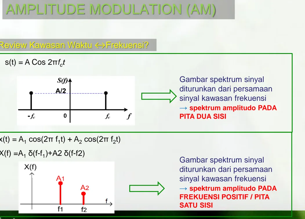
s(t) = A Cos 2πfct
Gambar spektrum sinyal diturunkan dari persamaan sinyal kawasan frekuensi
→ spektrum amplitudo PADA PITA DUA SISI
x(t) = A1 cos(2π f1t) + A2 cos(2π f2t) X(f) =A1 δ(f-f1)+A2 δ(f-f2)
AMPLITUDE MODULATION (AM)
Review Kawasan Waktu ↔Frekuensi?
Gambar spektrum sinyal diturunkan dari persamaan sinyal kawasan frekuensi
→ spektrum amplitudo PADA FREKUENSI POSITIF / PITA SATU SISI
Pada AM, amplitudo dibuat berubah sesuai
sinyal informasi, sedang phasanya dibuat nol.
AMPLITUDE MODULATION (AM)
Modulasi Amplituda (AM)
sehingga persamaan sinyal termodulasi secara umum
adalah:
S
AM(t) = m(t) cos ω
ct
1. Double Side Band Full Carrier (DSB-FC)
2. Double Side Band Suppressed Carrier (DSB-SC)
3. Single Side Band (SSB)
4. Vestigial Side Band (VSB)
AMPLITUDE MODULATION (AM)
Varian dari Modulasi Amplitudo
“Diagram Blok Modulasi AM-DSB-FC”
AMPLITUDE MODULATION (AM)
AM-DSB-FC
E B C D A AM DSB FC Sinyal info Sinyal carrier Amplifier Mixer F Sc(t) = Vc cos (ωct)AMPLITUDE MODULATION (AM)
AM-DSB-FC
Pembawa : S
c(t) = V
ccos (ω
ct)
Pemodulasi : m(t)
ka = sensitivitas Amplituda [per volt]
t
V
k
m
t
f
t
S
AM
c1
acos
2
cSc(t)
SAM(t)
AMPLITUDE MODULATION (AM)
AM-DSB-FC
| ka m(t) | ≤ 1 → tidak terjadi „over modulasi‟ menghindari Envelope Distortion fc >> fm agar bentuk envelope bisa dilihat (fm adalah komponen frekuensi tertinggi dari informasi)Syarat Modulasi AM :
t
V
k
m
t
f
t
S
AM
c1
acos
2
cm = μ = indeks modulasi = K
aV
mAMPLITUDE MODULATION (AM)
AM-DSB-FC Pemodulasi Sinusoidal Tunggal
2
min maxA
A
V
c
f
t
f
t
V
t
f
t
f
V
k
V
t
f
t
m
k
V
t
S
c m c c m m a c c a c AM
2
cos
2
cos
1
2
cos
2
cos
1
2
cos
1
t
V
f
t
S
t
f
V
t
m
c c c m m
2
cos
2
cos
min max min maxA
A
A
A
Amax Amin Amax Amin Amax Amin μ < 1 μ > 1 μ = 1
AMPLITUDE MODULATION (AM)
Indeks Modulasi AM-DSB-FC
min max min max
A
A
A
A
OVER MODULATIONSpektrum m(t) M(f)
AMPLITUDE MODULATION (AM)
Spektrum AM DSB FC
dengan informasi sinyal sinusoidal tunggal m(t) ↔ M(f) m(t) = Vm Cos 2πfmt Gambar Spektrum Sinyal DSB-FC
S
AM DSB FC( f
)
cf
f
c
f
m m cf
f
cf
f
c
f
m m cf
f
0
mf
2
2 c V 4 c V )
( f
M
mf
mf
0 2 m V Spektrum C(t) C(f) C(t) = Vc Cos 2πfctM
( f
)
cf
cf
0 2 c V Plus CARIERAMPLITUDE MODULATION (AM)
Spektrum AM DSB FC
dengan informasi sinyal sembarang m(t) ↔ M(f) INFORMASI MODULATED SIGNAL (AM-DSB-FC)
)
( f
M
BANDWITH: mf
mf
m mf
B
mB
0 mf
B
2
BW
AM-DSB-FC
)
( f
S
AM DSB FC cf
f
c
f
m m cf
f
cf
f
c
f
m m cf
f
USB
LSB
0
mB
mB
Spektrum C(t) C(f) C(t) = Vc Cos 2πfctM
( f
)
cf
cf
0 2 c V Plus CARIERAMPLITUDE MODULATION (AM)
Contoh Soal
Modulator AM fc= 500 kHz, Vc=10 volt ka = 0,4 per volt X Osilator BPF B C A D Z ant = 50 Info = m(t)Perhatikan pemancar AM-DSB-FC pada frekuensi radio 50 MHz (di titik D) dengan diagram blok sbb :
Persamaan umum sinyal AM-DSB-FC (di B atau di D) adalah: VAM(t) = Vc [ 1+ ka m(t) ] cos(2fct)
a) gambarkan gelombang sinyal AM DSB-FC (di B) pada gambar diatas, Jika m(t) = 1 cos(2.3400.t) ! Berikan skala amplitudo yang jelas !
b) Gambarkan spektrum sinyal AM DSB-FC di B, C dan di D !
AMPLITUDE MODULATION (AM)
Daya Pada sinyal AM-DSB-FC
t
V
k
m
t
f
t
S
AM
c1
acos
2
c
f
t
V
f
f
t
V
f
f
t
V
t
f
t
f
V
t
f
V
t
f
t
f
V
t
f
t
m
k
V
t
S
m c c m c c c c c m c c c c m c c a c AM
2
cos
2
2
cos
2
2
cos
2
cos
2
cos
2
cos
2
cos
2
cos
1
2
cos
1
2
cV
2
2
cV
Nilai RMS 2
2
cV
CARIER USB LSBAMPLITUDE MODULATION (AM)
Daya Pada sinyal AM-DSB-FC
R
V
R
V
R
V
R
V
R
V
R
V
P
P
P
P
c c c c c c LSB USB C AMDSB FC8
8
2
)
2
2
/
(
)
2
2
/
(
)
2
/
(
2 2 2 2 2 2 2 2
4
2
2
1
2
4
2
8
2
2
8
8
2
2 2 2 2 2 2 2 2 2 2 2 2 2 2 2
c c c c c c c c c AMV
V
V
V
V
V
R
V
R
V
R
V
P
FC DSBDaya pada Referensi Resistansi 1 ohm
AMPLITUDE MODULATION (AM)
Power Transmission Efficiency of AM-DSB-FC
2 2 2 2 2 22
4
2
4
c c LSB USB C LSB USBV
V
P
P
P
P
P
power
Total
power
sidaband
total
0,25 0,03 0,5 0,11 0,75 0,22 1 0,33
Dari Tabel Diatas bisa disimpulkan bahwa Efisiensi Power transmisi dari AM-DSB-FC meningkat jika index modulasinya
μ
dinaikkan, Tetapi meskipun index modulasinya sudah maksimalμ = 1
, hanya 1/3 dayanya berada pada sideband, sedangkanDilakukan dengan mendeteksi selubung (envelope) sinyal termodulasinya. Alat yang digunakan disebut Detektor
Selubung (Envelope Detector)
AMPLITUDE MODULATION (AM)
Demodulasi Sinyal AM-DSB-FC – Detector Selubung
AMPLITUDE MODULATION (AM)
Demodulasi Sinyal AM-DSB-FC – Detector Selubung
Sinyal AM-DSB-FC dengan index
modulasi 1/2
Output dari detektor selubung terlihat masih ada ripple bisa dihilangkan dengan LPF
AMPLITUDE MODULATION (AM)
Kesimpulan AM-DSB-FC
Pada AM-DSB-FC, sinyal sideband di transmisikan
bersama dengan cariernya
Sederhana dalam mendeteksi / Demodulasi detektor
selubung
Efisiensi Power transmisi rendah
“Diagram Blok Modulasi AM-DSB-SC”
AMPLITUDE MODULATION (AM)
AM-DSB-SC
B C A AM DSB SC Sinyal info Sinyal carrier Mixer Sc(t) = Vc cos (ωct) m(t) = Vm cos (ωmt)AMPLITUDE MODULATION (AM)
AM-DSB-SC
Pembawa : S
c(t) = V
ccos (ω
ct)
Pemodulasi : m(t)
t
V
V
f
t
f
t
S
AM c m c m SC DSB
cos
2
cos
2
Sc(t) SAM(t) m(t)AMPLITUDE MODULATION (AM)
AM-DSB-SC Pemodulasi Sinusoidal Tunggal
f f t f f t
V V t f t f V V t S m c m c m c c m m c AMDSB SC
2 cos 2 cos 2 2 cos 2 cos
t
V
f
t
S
t
f
V
t
m
c c c m m
2
cos
2
cos
AMPLITUDE MODULATION (AM)
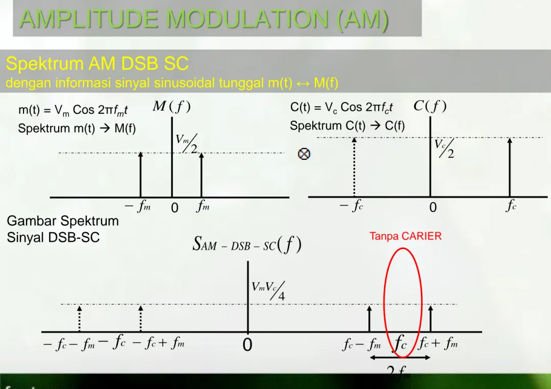
Spektrum AM DSB SC
dengan informasi sinyal sinusoidal tunggal m(t) ↔ M(f)
Gambar Spektrum Sinyal DSB-SC
S
( f
)
SC DSB AM cf
f
c
f
m m cf
f
cf
f
c
f
m m cf
f
0
mf
2
4 c mV V Tanpa CARIER Spektrum m(t) M(f) m(t) = Vm Cos 2πfmtM
( f
)
mf
mf
0 2 m V Spektrum C(t) C(f) C(t) = Vc Cos 2πfctC
( f
)
cf
cf
0 2 c VAMPLITUDE MODULATION (AM)
Spektrum AM DSB SC
dengan informasi sinyal sembarang m(t) ↔ M(f)
MODULATED SIGNAL (AM-DSB-SC) m
f
B
2
BW
AM-DSB-SC
)
( f
S
AM DSB SC cf
f
c
f
m m cf
f
cf
f
c
f
m m cf
f
USB
LSB
0
mB
mB
INFORMASIM
( f
)
BANDWITH: mf
mf
m mf
B
mB
0 Spektrum C(t) C(f) C(t) = Vc Cos 2πfctC
( f
)
cf
cf
0 2 c V Tanpa CARIERAMPLITUDE MODULATION (AM)
Daya Pada sinyal AM-DSB-SC
t
V
V
f
t
f
t
S
AM DSBSC
m ccos
2
mcos
2
c
f
f
t
V
V
f
f
t
V
V
t
f
t
f
V
V
t
S
m c c m m c c m c m c m AM
2
cos
2
2
cos
2
2
cos
2
cos
2
2
c mV
V
Nilai RMS 2
2
c mV
V
USB LSBAMPLITUDE MODULATION (AM)
Daya Pada sinyal AM-DSB-SC
R
V
V
R
V
V
R
V
V
R
V
V
P
P
P
c m c m c m c m LSB USB AMDSB SC8
8
)
2
2
/
(
)
2
2
/
(
2 2 2 2 2 2
4
8
2
8
2
8
8
2 2 2 2 2 2 2 2 2 2 c m c m c m c m c m AMV
V
V
V
R
V
V
R
V
V
R
V
V
P
SC DSB
Daya pada Referensi Proses demodulasi dilakukan dengan mengalikan sinyal carrier termodulasi dengan sinyal local oscillator (pada penerima) yang sama persis dengan sinyal oscillator pada pemancar, kemudian memasukan hasilnya ke sebuah low pass filter (LPF)
Syarat penting :Local Oscillator harus menghasilkan sinyal cos ωct yang frequency dan phasa nya sama dengan yang dihasilkan oleh oscillator pada pemancar
Synchronous Demodulation/Detection Coherent detection
AMPLITUDE MODULATION (AM)
Demodulasi/Deteksi Sinyal DSB-SC
B C A AM DSB SC Sinyal info Sinyal carrier Mixer Sc(t) = VLO cos (ωct) m(t) = Vm cos (ωmt) LPFAMPLITUDE MODULATION (AM)
Demodulasi/Deteksi Sinyal DSB-SC
B C A AM DSB SC Sinyal info Sinyal carrier Mixer SLO(t) = VLO cos (ωct) m(t) = Vm cos (ωmt) LPF
t VV
f t
f t
SAM c m c m SC DSB cos 2 cos 2 Sinyal di C D
f f t
V VV
f
t
V V V t f V V V t f f V V V t f t f f V V V t f t f f V V V t f V t f f V V t f f V V t f V t f t f V V t S m LO c m m c LO c m m LO c m m c LO c m c m c LO c m c m c LO c m c LO m c c m m c c m c LO c m c m C di 2 cos 4 2 2 cos 4 2 cos 4 2 2 cos 4 2 cos 2 cos 2 2 cos 2 cos 2 2 cos 2 cos 2 2 cos 2 2 cos 2 cos 2 cos Sinyal di D
f t
V V V t f V V V t f V V V t S m LO c m m LO c m m LO c m D di 2 cos 2 2 cos 4 2 cos 4 AMPLITUDE MODULATION (AM)
Modulasi AM-DSB-SC
AMPLITUDE MODULATION (AM)
Modulasi AM-DSB-SC
(informasi/pemodulasi sembarang m(t) – analisa kawasan frekuensi) MODULATED SIGNAL (AM-DSB-SC)
) ( f SAM DSBSC c f fc fm m c f f c f fc fm m c f f
0
Spektrum SLO(t) SLO(f) SLO(t) = VLO Cos 2πfct ) ( f C c f c f 0 2 LO V ) ( f SoutMix c f c f 0
Output demodulator c f 2 c f 2 Output dari LPFAMPLITUDE MODULATION (AM)
Kesimpulan AM-DSB-SC
Less transmitted power than AM-DSB-FC and all the
transmitted power is useful.
Requires a coherent carrier at the receiver; This results in
increased complexity in the detector(i.e. synchroniser)
Dikembangkan karena DSB-SC membutuhkan Bandwith yang besar (2 kali bandwith sinyal informasi)
Ternyata USB atau LSB mengandung informasi yang lengkap, sehingga dirasa cukup mentransmisikan salah satu side band saja
Dua tipe AM-SSB AM-SSB-USB dan AM-SSB-LSB
AMPLITUDE MODULATION (AM)
AM-SSB (Single Side Band)
“Diagram Blok Modulasi AM-SSB”
B C A AM SSB Sinyal info Sinyal carrier Mixer Sc(t) = VLO cos (ωct) m(t) = Vm cos (ωmt) BPF
AMPLITUDE MODULATION (AM)
AM-SSB Pemodulasi Sinusoidal Tunggal
f f
t V V t f f V V t f f t f f V V t f t f V V t S m c m c m c m c m c m c m c c m m c AMSSB
2 cos 2 2 cos 2 2 cos 2 cos 2 2 cos 2 cos
t
V
f
t
S
t
f
V
t
m
c c c m m
2
cos
2
cos
KASUS AM-SSB-USB KASUS AM-SSB-LSBAMPLITUDE MODULATION (AM)
Daya Pada sinyal AM-SSB
t
V
V
f
t
f
t
S
AM SSB
m ccos
2
mcos
2
c
f
f
t
V
V
f
f
t
V
V
t
f
t
f
V
V
t
S
m c c m m c c m c m c m AM
2
cos
2
2
cos
2
2
cos
2
cos
2
2
c mV
V
Nilai RMS 2
2
c mV
V
USB LSBAMPLITUDE MODULATION (AM)
Daya Pada sinyal AM-DSB-SC
R
V
V
R
V
V
P
P
P
P
c m c m LSB USB AM AMSSB USB SSB LSB8
)
2
2
/
(
2 2 2
8
8
2 2 2 2 c m c m AM AMV
V
R
V
V
P
P
LSB SSB USB SSB
Daya pada ReferensiAMPLITUDE MODULATION (AM)
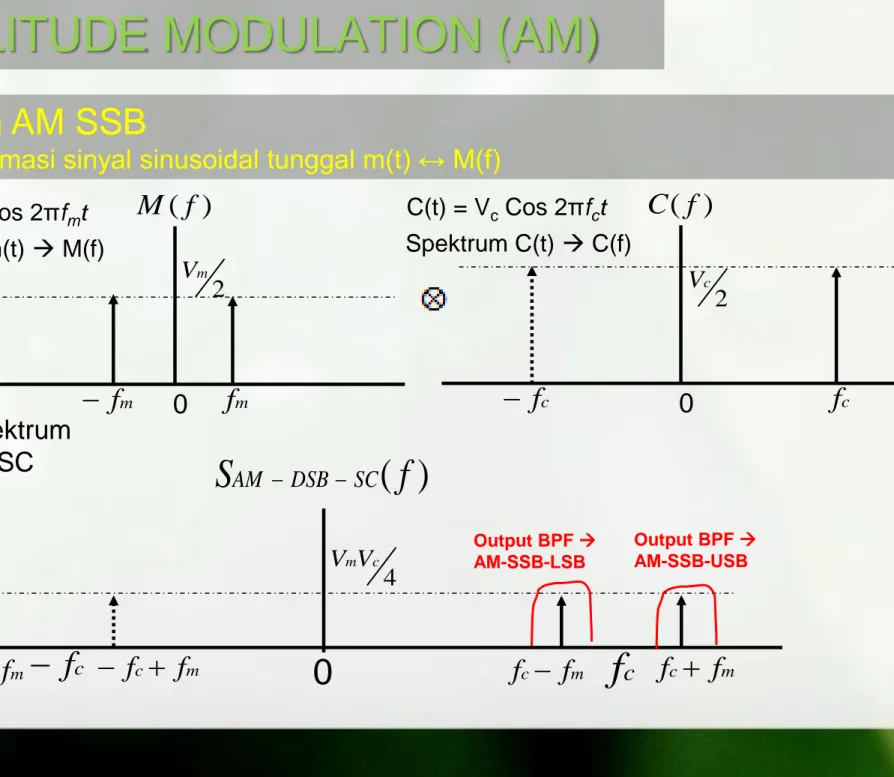
Spektrum AM SSB
dengan informasi sinyal sinusoidal tunggal m(t) ↔ M(f)
Gambar Spektrum Sinyal DSB-SC
S
( f
)
SC DSB AM cf
f
c
f
m m cf
f
cf
f
c
f
m m cf
f
0
4 c mV V Output BPF AM-SSB-USB Spektrum m(t) M(f) m(t) = Vm Cos 2πfmtM
( f
)
mf
mf
0 2 m V Spektrum C(t) C(f) C(t) = Vc Cos 2πfctC
( f
)
cf
cf
0 2 c V Output BPF AM-SSB-LSBAMPLITUDE MODULATION (AM)
Spektrum AM SSB
dengan informasi sinyal sembarang m(t) ↔ M(f)
MODULATED SIGNAL (AM-DSB-SC) m
f
B
BW
AM-DSB-SC
)
( f
S
AM SSB cf
f
c
f
m m cf
f
cf
f
c
f
m m cf
f
0
mB
mB
INFORMASIM
( f
)
BANDWITH: mf
mf
m mf
B
mB
0 Spektrum C(t) C(f) C(t) = Vc Cos 2πfctC
( f
)
cf
cf
0 2 c V Output BPF AM-SSB-USB Output BPF AM-SSB-LSB Proses demodulasi dilakukan dengan Cara yang sama dengan AM-DSB-SC
AMPLITUDE MODULATION (AM)
Demodulasi/Deteksi Sinyal AM-SSB
B C A AM DSB SC Sinyal info Sinyal carrier Mixer Sc(t) = VLO cos (ωct) m(t) = Vm cos (ωmt) LPF
AMPLITUDE MODULATION (AM)
Demodulasi/Deteksi Sinyal AM-SSB
B C A AM DSB SC Sinyal info Sinyal carrier Mixer SLO(t) = Vc cos (ωct) m(t) = Vm cos (ωmt) LPF
t VV
f f
t S c m c m AMSSBUSB cos 2 2 Sinyal di C D
f f t
V VV
f t
V V V t f V t f f V V t S m LO c m m c LO c m c LO m c c m C di 2 cos 4 2 2 cos 4 2 cos 2 cos 2 Sinyal di D
t V VV
f t
SdiD m c LO cos 2 m 4 AMPLITUDE MODULATION (AM)
Modulasi AM-SSB
(informasi/pemodulasi sembarang m(t) – analisa kawasan frekuensi) MODULATED SIGNAL (AM-SSB-USB)
) ( f SAM DSBSC c f fc fm m c f f c f fc fm m c f f
0
Spektrum SLO(t) SLO(f) SLO(t) = VLO Cos 2πfct ) ( f C c f c f 0 2 LO V ) ( f SoutMix c f c f 0
Output demodulator c f 2 c f 2 Output dari LPFAMPLITUDE MODULATION (AM)
Kesimpulan AM-SSB
Good bandwidth utilization (message signal
bandwidth = modulated signal bandwidth)
Good power efficiency
Demodulation is harder as compares to AM-DSB-FC;
Exact filter design and coherent demodulation are
DSB memiliki kelemahan karena membuang-buang bandwidth
dan power, sedangkan SSB meskipun lebih efisien (BW dan
Power) tetapi sulit dalam praktek karena butuh filter yang sangat
ideal dan biasanya low frekuensi mengandung informasi yang
penting
VSB Merupakan kompromi (jalan tengah) antara SSB dan DSB
Biasanya digunakan dalam transmisi sinyal video pada televisi
AMPLITUDE MODULATION (AM)
AM-VSB (Vestigial Side Band)
• Sinyal VSB dapat dibangkitkan dengan proses seperti
terlihat pada diagram blok berikut
AMPLITUDE MODULATION (AM)
Pembangkitan Sinyal VSB
AMPLITUDE MODULATION (AM)
Pembangkitan Sinyal VSB
AMPLITUDE MODULATION (AM)
Kesimpulan AM-VSB
Offers a compromise between SSB and DSB-SC
VSB is standard for transmission of TV and similar signals
Bandwidth saving can be significant if modulating signals are
of large bandwidth as in TV and wide band data signals.
For example with TV the bandwidth of the modulating signal can extend
up to 5.5MHz; with full AM the bandwidth required is 11MHz
Modulasi, Demodulasi, Kinerja Sistem
Frequency Modulation (FM)
FREQUNCY MODULATION (FM)
Pembentukan sinyal FM
Pembawa : S
c(t) = V
ccos (ω
ct)
Pemodulasi : m(t)
kf = sensitivitas Frekuensi [Hz/volt]
t f c c FMt
V
f
t
k
m
t
dt
S
02
2
cos
Sc(t) SFM(t) m(t)FREQUENCY MODULATION
SFM(t)
FM Pemodulasi Sinusoidal Tunggal
f
t
f
t
V
t
f
f
f
t
f
V
t
f
f
f
t
f
V
dt
t
f
V
k
t
f
V
dt
t
f
V
k
t
f
V
dt
t
m
k
t
f
V
t
S
m c c m m c c m m c c t m m f c c t m m f c c t f c c FM
2
sin
2
cos
2
sin
2
cos
2
sin
2
2
2
cos
2
cos
2
2
cos
2
cos
2
2
cos
2
2
cos
0 0 0
t
V
f
t
S
t
f
V
t
m
c c c m m
2
cos
2
cos
t
f
k
V
f
t
f
i
c
f mcos
2
m m fV
k
f
dt t d t fi
i
2 1 f
f
f
f
f
f
i max
c
;
i min
c
i
tf
mf
Deviasi frekuensi Index Modulasi Sudut/Angular Frekuensi SesaatFREQUENCY MODULATION
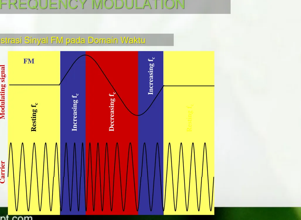
Ilustrasi Sinyal FM pada Domain Waktu
Res ting fc Incr ea sing fc Incr ea sing fc Decr ea sing f c Res tin g f c M o dula ting sig na l Ca rrier FM
When m(t) is a band of signals, e.g. speech or
music the analysis is very difficult (impossible?).
Calculations usually assume a single tone
frequency equal to the maximum input frequency.
E.g. m(t)
band 20Hz
15kHz, fm = 15kHz is used
.
FREQUENCY MODULATION
Berikut ini adalah persamaan FM untuk info single tone :
Persamaan tersebut dapat dijabarkan menjadi persamaan berikut :
FREQUENCY MODULATION (FM)
Spectrum FM untuk info Single Tone
t
V
f
t
f
t
S
FM
ccos
2
c
sin
2
m
t
V
J
f
n
f
t
S
FM
c
n
cos
2
c
2
mDimana Jn(β) adalah fungsi bessel dan sudah disediakan dalam bentuk grafik dan tabel
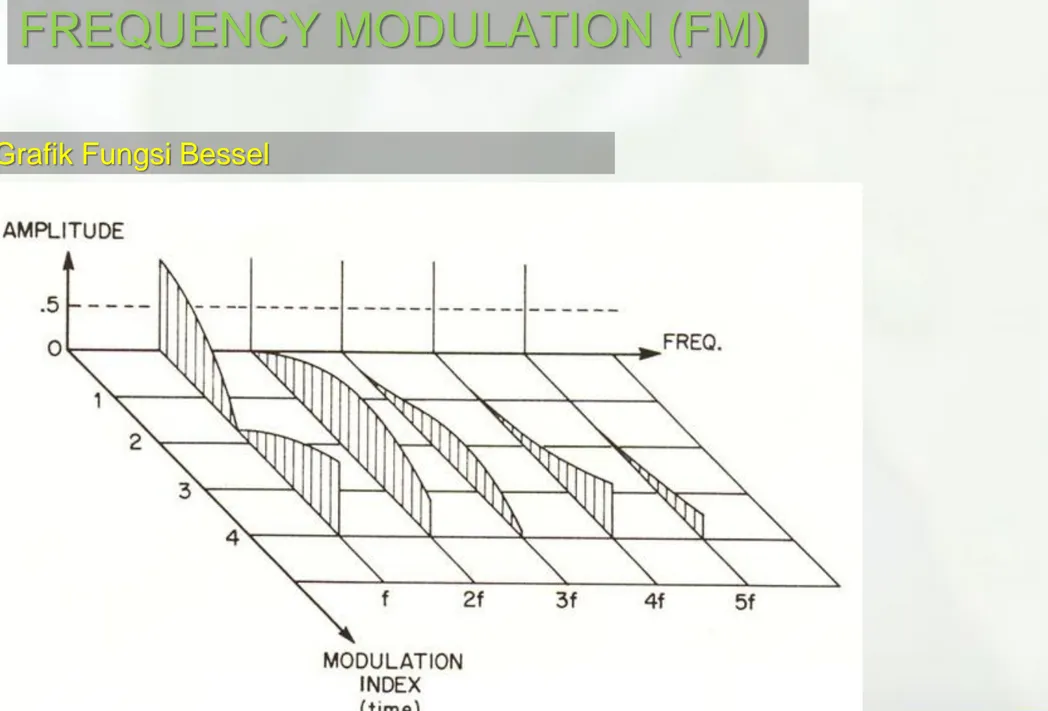
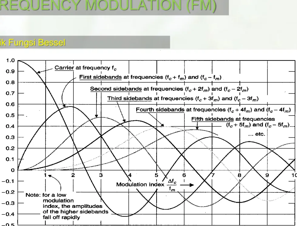
Grafik Fungsi Bessel
Grafik Fungsi Bessel
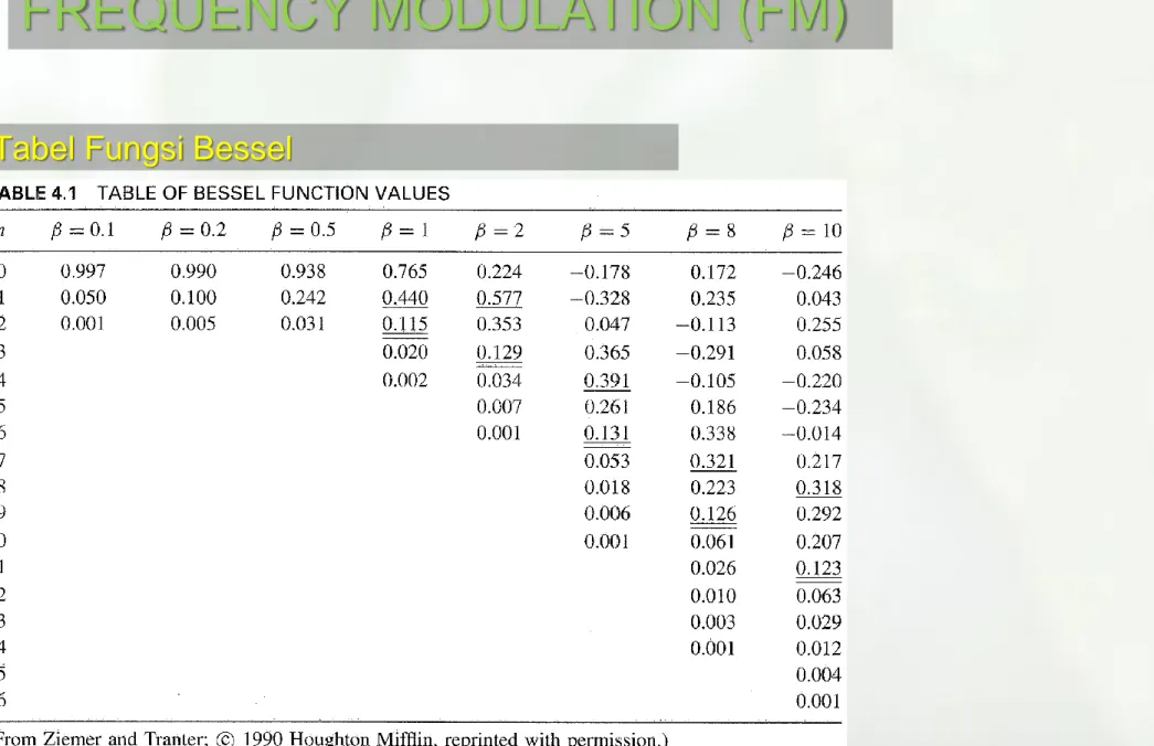
Tabel Fungsi Bessel
Keterangan Fungsi Bessel
Fungsi bessel merepresentasikan sideband – sideband yang
muncul diantara frekuensi carrier dan terletak pada frekuensi
informasi dan kelipatannya.
Jumlah sideband pada fungsi bessel tak hingga.
Pada sinyal FM, fungsi bessel menentukan amplituda sinyal
carrier dan amplituda sidebandnya.
Sideband yang amplitudanya kurang dari 1% amplituda
sinyal carrier, dapat diabaikan.
= 0
= 2.4
J0(2.4) = 0, J1(2.4) = 0.5, J2(2.4) = 0.45 and J3(2.4) = 0.2
Contoh Spektrum FM (Fungsi Bessel)
Saat = 0 hanya ada carier dan tidak ada info yang dimodulasi dan J0(0) = 1, dan nilai Jn(0) = 0,
Dari Grafik (pendekatan)
Spectrum sinyal FM untuk beberapa index modulasi
=0.5 =1
=5 =10
Example: A message signal with a frequency fm Hz modulates a carrier fc to produce FM with a modulation index = 1. Sketch the spectrum.
n Jn(1) Amplitude Frequency 0 0.7652 0.7652Vc fc 1 0.4400 0.44Vc fc+fm fc - fm 2 0.1149 0.1149Vc fc+2fm fc - 2fm 3 0.0196 0.0196Vc fc+3fm fc -3 fm 4 0.0025 Insignificant 5 0.0002 Insignificant
Significant Sideband
FREQUENCY MODULATION (FM)
Seperti terlihat pada tabel fungsi bessel, untuk nilai n diatas nilai tertentu,
nilai J
n(
) menjadi sangat kecil. Pada FM spectrum sideband dianggap
signifikan jika J
n(
)
0.01 (1%).
Meskipun sebenarnya BW signal FM tidak terbatas, tetapi komponen
sideband dengan amplituda V
cJ
n(
) dimana J
n(
) < 0.01 menjadi tidak
signifikan dan bisa diabaikan
Significant Sideband
As shown, the bandwidth of the spectrum containing significant
components is 6f
m, for
= 1.
Significant Sideband
The table below shows the number of significant sidebands for various modulation indices () and the associated spectral bandwidth.
No of sidebands 1% of unmodulated carrier Bandwidth 0.1 2 2fm 0.3 4 4fm 0.5 4 4fm 1.0 6 6fm 2.0 8 8fm 5.0 16 16fm 10.0 28 28fm
FREQUENCY MODULATION (FM)
Secara teoritis, bandwidth sinyal FM adalah tak hingga. Hal ini
bisa dilihat pada grafik fungsi bessel
Untuk pendekatan, maka bandwidth FM didekati dengan
BANDWIDTH CARSON:
BW = 2 (∆f + fm) = 2fm(β+1)
Pada BANDWIDTH CARSON kandungan energi sinyal FM adalah 99 % dari kandungan energi total sinyal FM
Δf = deviasi frekuensi maksimum (untuk informasi sinyal sembarang) Δf = deviasi frekuensi(untuk informasi sinyal single tone)
fm = frekuensi pemodulasi/informasi maksimum (untuk informasi sinyal sembarang)
fm = frekuensi pemodulasi/informasi (untuk informasi sinyal single tone)
Bandwidth FM
Bandwidth FM
Seperti terlihat pada tabel fungsi bessel, terlihat bahwa ketika
amplituda pada sideband meningkat, amplituda pada carier, J
0turun.
Hal ini dikarenakan pada FM, total daya transmit selalu konstan
dan rata-rata daya total sama dengan daya carier
(unmodulated), sehingga daya FM selalu konstan baik dengan
maupun tanpa ada sinyal pemodulasi
Sehingga efeknya, total daya yang awalnya berada di carier
menjadi terdistribusi pada seluruh spectrum komponen
sidebandnya, pada batas nilai signifikan dalam fungsi besel
untuk nilai index modulasi tertentu.
Pada nilai index modulasi tertentu, amplitudo carier bisa sama
dengan nol, dimana dayanya dibawa hanya oleh sidebandnya
saja
Null Carrier
FM Power Distribution
Dari Persamaan sinyal FM :
Kita bisa lihat bahwa nilai maksimum dari komponennya adalah VcJn() untuk komponen ke n
Nilai daya rata-rata untuk satu komponen =
R V R V pk RMS 2 2 2 ) (
R
J
V
R
J
V
n c n c2
)
(
2
)
(
2 2
sehingga, total daya pada spectrum yang tak terbatas adalah :
n n c TJ
V
P
2
))
(
(
2FM Power Distribution
sehingga daya rata-rata untuk komponen ke-n adalah =
Dengan cara ini kita harus menghitung seluruh
komponen spectrum FM yang tidak terbatas untuk menghitung daya total FM
t
V
J
f
n
f
t
S
FM
c
n
cos
2
c
2
mTotal Daya rata-rata pada Referensi Resistansi 1 ohm
2
2
2 c pk RMSV
V
V
Sehingga rata-rata daya total pada referensi 1 ohm bisa kita tuliskan :
2
2
2
)
(
2 c 2 c2 n n c TV
V
J
V
P
Sehingga jika kita tahu amplitudacarier Vc dari sinyal FM, maka daya rata-rata total FM untuk seluruh spectrum bisa dihitung dengan mudah
FM Power Distribution
Tapi, karena terlihat dari bentuk gelombang FM, dimana nilai maksimumnya konstan sebesar Vc, maka :
c
V
Sehingga nilai RMS nya adalah :
FM Power Distribution-Contoh
Misalkan suatu FM broadcasting mengirimkan suara 4 Khz dengan
deviasi frequensi 2 Khz, jika diketahui tegangan carier sebelum modulasi
adalah 10 V rms pada impedance 50 ohm, maka berapa daya FM ?
carier voltage =10x0,94 = 9,4 volt Daya = 9,42/50=1,7672 watt
the first sideband voltage =10x0,24=2,4volt Daya =2,42/50 x 2pair = 0,2304 watt
second sideband voltage = 10x0,03=0,3 volt Daya =0,32/50=0,0018 x2pair = 0,0036 watt
Daya Total= 1,7672+0,2304+0,0036 = 102/50=2 Watt
5
,
0
4
2
khz
khz
f
f
m
JAWAB : β Carrier Sideband 1st 2nd 0,5 0,94 0,24 0,03FREQUENCY MODULATION (FM)
Contoh Soal
a. Gambarkan gelombang sinyal FM (di B) pada gambar diatas
(domain waktu)
b. Hitung bandwidth carson dan daya rata-rata FM (di B)
c. Gambarkan spektrum sinyal FM di B, C dan di D !
Perhatikan pemancar FM dengan diagram blok sbb :
m(t) = cos(2.2000.t)
SLO(t) = VLOcos(2.92.106.t) BPF : 102,690 – 102,72 Mhz
Secara garis besar ada 2 cara untuk
membuat modulator FM
1. Direct Method Menggunaka VCO (Voltage
Controlled Oscilator)
2. Indirect Method Menggunakan Frequency
Multiplier
Generation of FM
Blok Diagram pembentukan signal FM :
Sinyal pemodulasi (informasi) secara langsung mengontrol sinyal carrier, contohnyaadalah dengan menggunakan
Voltage Controlled Oscillator(VCO)
Generation of FM –Direct Method
FREQUENCY MODULATION (FM)
V/F
INV
t
m
OUTf
t
S
FM VCOFrekuensi output secara bertahap berubah dari f
cke (f
c+ K
fV
m), kembali ke
f
ckemudian menuju (f
c- K
fV
m)
Generation of FM –Direct Method
m f c i f k V f min m f c i f k V f max max i f fi min
FREQUENCY MODULATION (FM)
Jika kita plot fOUT sebagai fungsi dari VIN:
Secara umum, m(t) akan berupa “signal dengan Band tertentu” sehingga akan terdiri dari variasi amplituda dan frekuensi. Keduanya baik perubahan frekuensi atau amplituda disisi input akan di ubah hanya perubahan frekuensi disisi output, sedangkan amplituda outputnya konstan
Generation of FM –Direct Method
m f c out f k V f m f c out f k V f
FREQUENCY MODULATION (FM)
Generation of FM –Indirect Method
NBPM Modulator Integrator
Pada metode ini, sinyal termodulasi sudut pita sempit yang telah
diproduksi dikalikan n oleh sebuah multiplier, sehinngga diperoleh sinyal termodulasi sudut pita lebar
NBFM ∆f<<fm BFM=2fm β<0,3 WBFM ∆f>>fm BFM=2 ∆f β>1
FREQUENCY MODULATION (FM)
43
• Types of FM Detectors:
1. Differentiator with envelope detector (FM to AM
convertion)
2. Zero Crossing detector
3. Centre Tuned Discriminator / Phase
Discriminator / Foster – Seeley Discriminator
4. Phase Locked Loop (PLL) Demodulator
5. Ratio Detector
FM Demodulation –General Principles.
FM Demodulation –Differentiator with envelope detector
Limiter Limiter merupakan perangkat yang outputnya akan konstan jika amplituda input melebihi dari nilai threshold
Fungsi Limiter pada FM reciever adalah untuk menghilangkan variasi amplitudo dari signal FM yang tidak diinginkan
Diskriminator
Pada sinyal FM informasi terkandung pada frekuensi sinyal FM