MODULASI
ANALOG
By : Dwi Andi Nurmantris
DTG2F3
Sistem
Komunikasi
OUTLINE
1. Penerapan Tranformasi Fourier dalam
Sistem Komunikasi
2. Modulasi, Demodulasi, dan Kinerja
Sistem AM
3. Modulasi, Demodulasi, dan Kinerja
Sistem FM
4. Radio Broadcasting (AM dan FM) &
TV Broadcasting (Analog)
Penerapan Transformasi Fourier dalam
Sistem Komunikasi
TRANSFORMASI FOURIER
Time and Frequency Domain
Domain Waktu dan domain Frekuensi dari gelombang
sinusoidal
Suatu sinyal dapat direpresentasikan dalam domain waktu ataupun
frekuensi
Dalam domain waktu
direpresentasikan dalam bentuk tegangan atau arus dalam fungsi waktu
Dalam domain frekuensi
direpresentasikan dalam bentuk magnitudo dan fasa dalam fungsi frekuensi
Transformasi fourier berfungsi
sebagai pengubah representasi sinyal dari domain waktu s(t) kedalam
domain frekuensi S(f)
Inverse Transformasi Fourier melakukan fungsi sebaliknya
TRANSFORMASI FOURIER
Time and Frequency Domain
The time-domain and frequency-domain plots of a
DC Signal
The time domain and frequency domain of three
According to Fourier analysis, any
composite signal is a combination of
simple sine waves with different
frequencies, amplitudes, and phases.
TRANSFORMASI FOURIER
TRANSFORMASI FOURIER
Fourier Analysis
X( f )
x(t)e
j 2ftdt
x(t)
X( f )e
j 2ftdf
Fourier TransformTime domain Frequency Domain
Inverse Fourier Transform
Frequency domain Time Domain
)
(
)
(
t
F
j
TRANSFORMASI FOURIER
Beberapa Transformasi Penting
TRANSFORMASI FOURIER
Sifat Penting Transformasi Fourier
Time Scaling
t
S
f
s
a
f
S
a
at
s
1
Time Shifting
t
X
f
x
2
0
0
X
f
e
j
ft
t
t
x
TRANSFORMASI FOURIER
Sifat Penting Transformasi Fourier
Frequency Shifting
→ spektrum
amplitudo PADA PITA DUA SISI
TRANSFORMASI FOURIER
Sifat Penting Transformasi Fourier
Konvolusi di kawasan waktu
[1]
x(t) h(t) y(t) = ...? x(t) t 4 0 4 h(t) 6 0 t 2TRANSFORMASI FOURIER
TUGAS 2 (Review PSTM)
x(t) t 0 δ(t – to) t A 0 to x(t-to) t 0 A to
[2] Konvolusi dengan fungsi δ (t-to)
TRANSFORMASI FOURIER
Modulasi, Demodulasi, Kinerja Sistem
Amplitude Modulation (AM)
• Meminimalisasi interferensi sinyal pada
pengiriman informasi yang
menggunakan frequency sama atau
berdekatan
• Dimensi antenna menjadi lebih mudah
diwujudkan
• Sinyal termodulasi dapat dimultiplexing
dan ditransmisikan via sebuah saluran
transmisi
AMPLITUDE MODULATION (AM)
Mengapa Perlu Modulasi?
Modulasi adalah pengaturan parameter
dari sinyal pembawa (carrier) yang berfrekuensi tinggi sesuai sinyal informasi
(pemodulasi) yang frequensinya lebih
rendah, sehingga informasi tadi dapat
Persamaan Sinyal Pembawa/ Carrier:
V
c(t) = V
csin (
ω
ct + θ)
Amplitude modulation (AM)
Modulasi Sudut (Angle Modulation)
Phase Modulation
(PM)
Frequency Modulation
(FM)
(ωct + θ)
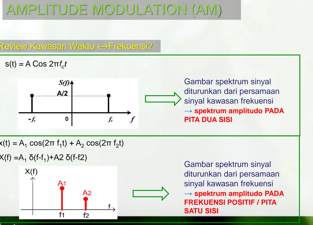
AMPLITUDE MODULATION (AM)
s(t) = A Cos 2πfct
Gambar spektrum sinyal diturunkan dari persamaan sinyal kawasan frekuensi
→ spektrum amplitudo PADA PITA DUA SISI
x(t) = A1 cos(2π f1t) + A2 cos(2π f2t) X(f) =A1 δ(f-f1)+A2 δ(f-f2)
AMPLITUDE MODULATION (AM)
Review Kawasan Waktu ↔Frekuensi?
Gambar spektrum sinyal diturunkan dari persamaan sinyal kawasan frekuensi
→ spektrum amplitudo PADA FREKUENSI POSITIF / PITA SATU SISI
Pada AM, amplitudo dibuat berubah sesuai
sinyal informasi, sedang phasanya dibuat nol.
AMPLITUDE MODULATION (AM)
Modulasi Amplituda (AM)
sehingga persamaan sinyal termodulasi secara umum
adalah:
S
AM(t) = m(t) cos ω
ct
1. Double Side Band Full Carrier (DSB-FC)
2. Double Side Band Suppressed Carrier (DSB-SC)
3. Single Side Band (SSB)
4. Vestigial Side Band (VSB)
AMPLITUDE MODULATION (AM)
“Diagram Blok Modulasi AM-DSB-FC”
AMPLITUDE MODULATION (AM)
AM-DSB-FC
E B C D A AM DSB FC Sinyal info Sinyal carrier Amplifier Mixer F Sc(t) = Vc cos (ωct)AMPLITUDE MODULATION (AM)
AM-DSB-FC
Pembawa : S
c(t) = V
ccos (ω
ct)
Pemodulasi : m(t)
ka = sensitivitas Amplituda [per volt]
t
V
k
m
t
f
t
S
AM
c1
acos
2
cSc(t)
SAM(t)
AMPLITUDE MODULATION (AM)
AM-DSB-FC
| ka m(t) | ≤ 1 → tidak terjadi ‘over modulasi’ menghindari Envelope Distortion fc >> fm agar bentuk envelope bisa dilihat (fm adalah komponen frekuensi tertinggi dari informasi)Syarat Modulasi AM :
t
V
k
m
t
f
t
m = μ = indeks modulasi = K
aV
mAMPLITUDE MODULATION (AM)
AM-DSB-FC Pemodulasi Sinusoidal Tunggal
2
min maxA
A
V
c
f
t
f
t
V
t
f
t
f
V
k
V
t
f
t
m
k
V
t
S
c m c c m m a c c a c AM
2
cos
2
cos
1
2
cos
2
cos
1
2
cos
1
t
V
f
t
S
t
f
V
t
m
c c c m m
2
cos
2
cos
min max min maxA
A
A
A
Amax Amin Amax Amin Amax Amin μ < 1 μ > 1 μ = 1
AMPLITUDE MODULATION (AM)
Indeks Modulasi AM-DSB-FC
min max min max
A
A
A
A
OVER MODULATIONSpektrum m(t) M(f)
AMPLITUDE MODULATION (AM)
Spektrum AM DSB FC
dengan informasi sinyal sinusoidal tunggal m(t) ↔ M(f)
m(t) = Vm Cos 2πfmt
M
( f
)
mf
mf
0Gambar Spektrum Sinyal DSB-FC
)
( f
S
AM DSB FC cf
f
c
f
m m cf
f
cf
f
c
f
m m cf
f
0
mf
2
2 c V 4 c V 2 m VAMPLITUDE MODULATION (AM)
Spektrum AM DSB FC
dengan informasi sinyal sembarang m(t) ↔ M(f) INFORMASI MODULATED SIGNAL (AM-DSB-FC)
)
( f
M
BANDWITH: mf
mf
m mf
B
mB
0 mf
B
2
BW
AM-DSB-FC
)
( f
S
AM DSB FC cf
f
c
f
m m cf
f
cf
f
c
f
m m cf
f
USB
LSB
0
mB
mB
AMPLITUDE MODULATION (AM)
Contoh Soal
Modulator AM fc= 500 kHz, Vc=10 volt ka = 0,4 per volt X Osilator BPF B C A D Z ant = 50 Info = m(t)Perhatikan pemancar AM-DSB-FC pada frekuensi radio 50 MHz (di titik D) dengan diagram blok sbb :
Persamaan umum sinyal AM-DSB-FC (di B atau di D) adalah: VAM(t) = Vc [ 1+ ka m(t) ] cos(2fct)
a) gambarkan gelombang sinyal AM DSB-FC (di B) pada gambar diatas, Jika m(t) = 1 cos(2.3400.t) ! Berikan skala amplitudo yang jelas !
b) Gambarkan spektrum sinyal AM DSB-FC di B, C dan di D !
AMPLITUDE MODULATION (AM)
Daya Pada sinyal AM-DSB-FC
t
V
k
m
t
f
t
S
AM
c1
acos
2
c
f
t
V
f
f
t
V
f
f
t
V
t
f
t
f
V
t
f
V
t
f
t
f
V
t
f
t
m
k
V
t
S
m c c m c c c c c m c c c c m c c a c AM
2
cos
2
2
cos
2
2
cos
2
cos
2
cos
2
cos
2
cos
2
cos
1
2
cos
1
2
cV
2
2
cV
Nilai RMS 2
2
cV
AMPLITUDE MODULATION (AM)
Daya Pada sinyal AM-DSB-FC
R
V
R
V
R
V
R
V
R
V
R
V
P
P
P
P
c c c c c c LSB USB C AMDSB FC8
8
2
)
2
2
/
(
)
2
2
/
(
)
2
/
(
2 2 2 2 2 2 2 2
4
2
2
1
2
4
2
8
2
2
8
8
2
2 2 2 2 2 2 2 2 2 2 2 2 2 2 2
c c c c c c c c c AMV
V
V
V
V
V
R
V
R
V
R
V
P
FC DSBDaya pada Referensi Resistansi 1 ohm
AMPLITUDE MODULATION (AM)
Power Transmission Efficiency of AM-DSB-FC
2 2 2 2 2 22
4
2
4
c c LSB USB C LSB USBV
V
P
P
P
P
P
power
Total
power
sidaband
total
0,25 0,03 0,5 0,11 0,75 0,22 1 0,33
Dari Tabel Diatas bisa disimpulkan bahwa Efisiensi Power transmisi dari AM-DSB-FC meningkat jika index modulasinya
μ
dinaikkan, Tetapi meskipun index modulasinya sudah maksimalμ = 1
, hanya 1/3 dayanya berada pada sideband, sedangkanDilakukan dengan mendeteksi selubung (envelope) sinyal termodulasinya. Alat yang digunakan disebut Detektor
Selubung (Envelope Detector)
AMPLITUDE MODULATION (AM)
Demodulasi Sinyal AM-DSB-FC – Detector Selubung
AMPLITUDE MODULATION (AM)
Demodulasi Sinyal AM-DSB-FC – Detector Selubung
Sinyal AM-DSB-FC dengan index
modulasi 1/2
Output dari detektor selubung terlihat masih ada ripple bisa dihilangkan dengan LPF