Quality of Service Improvement with 802.11e EDCA
Scheme Using Enhanced Adaptive Contention
Window Algorithm
Susan Prasetya
Basuki Rahmat
Erwin Susanto
Telecommunication Engineering
Abstract — Users of data services is growing exponentially and
the content accessed by the users are mostly real time and multimedia communications. The most connection commonly used is wireless LAN IEEE 802.11. Quality of Service (QoS) is a mandatory requirement in Wifi to support network limited capacity. IEEE 802.11e introduce a new standard of QoS which is called Enhanced Distributed Channel Access (EDCA). This standard has gave a new method for QoS support compared with previous method called Distributed Coordination Function (DCF). EDCA scheme provide four type of traffic (background task, best effort, video and voice) which is called Access Category (AC) to define the priority. There are three main parameters in EDCA to improve Quality of Service i.e TXOP (Transmission Opportunity), AIFS (Arbitrary Inter Frame Space) and CW (Contention Windows). Based on the main reference for throughput and delay improvement, this research will focus on contention window adjustment. Adjustment depends on number of stations involved in the network and collision probability. The more number of stations or the lower contention window value will result higher collision probability. To validate the result of contention window adjustment, simulation using NS-2 is applied. Simulation is done during low traffic (non-saturated) and high traffic (saturated) network. The proposed algorithm leads the throughput improvement by 2.29% and delay improvement by 3.32% in average for all traffic category.
Index Terms—Wifi, Qos, 802.11e, contention window, collision
probability.
I. INTRODUCTION
Traffic from mobile network increase very fast and it should be managed efficiently by operator to deliver service to customer. Offloading 3G or LTE traffic to Wifi network is the most optimum solution for above case. The IEEE 802.11b
There is a constraint on the Wifi network related with QoS (Quality of Service) since Wifi using media sharing method that relies on CSMA/CA (Carrier Sense Multiple Access with Collision Avoidance). This constraint is especially for real-time services for example Video streaming and voice calls that
require high quality data throughput to deliver the services properly. If many clients send packets simultaneously to the access point, there will be collisions that cause throughput degradation, packet loss, jitter and high latency. To avoid this problem, IEEE 802.11 Wifi technology has implemented Quality of Service mechanisms and documented in the 802.11e standard. QoS standards that exist in the 802.11e is HCCA (HCF Controlled Channel Access) and EDCA (Enhanced Distributed Channel Access).
This research refer algorithm in previous studies then make an adaptive contention window adjustment and carry out simulations based on Quality of Service EDCA in Wi-Fi network to get better throughput and delay performance. Simulation will be done for low and high traffic with VOIP, video and ftp packet using NS-2. In the last discussion, result from previous and proposed method is compared to validate the contention window algorithm improvement.
II. QOS AND EVOLUTION TO IEEE.802.11E
Wireless network is different with wired wired environments. This differences especially in delivering QoS to the customers. Bandwidth is an important resource in wireless network since it is related with channel that used by the users and can be interfered by other wireless source. Outside interference can be a root-cause impacting network performance. The performance impact are high packet loss, long delay, high jitter and low throughput. It should be a different way to implement QoS in wireless network compared to wired network.
2.1 Legacy IEEE 802.11
Wifi network or IEEE 802.11 is a standard distributed coordination function (DCF) and depends on multiple access method. By this method, each mobile node sends its packet or frame (MSDUs) after checking the media and sensing that no other mobile nodes sending the packet to media. If some stations know the channel is idle, the collision occurrence is inevitable if they transmit simultaneously. Some method are used in 802.11 standard to prevent packet or frame collisions when many mobile node sending to frame to media simultaneously. In Wifi network only one mobile node can send the packet to the media in one time because Wifi is using half duplex standard. There is no mechanism to set the Wifi in the duplex mode because of physical and frequency scheme. Therefore IEEE 802.11 working group setup a collision avoidance mechanism to prevent or reduce the collision probability. By this method, mobile node start a back-off setting before transmission and stay idle until a certain random period of soon after no traffic in the media during DCF Inter frame Space (DIFS) [7].
Distributed coordination function (DCF) is standard of mac address adjustment in the IEEE 802.11e. The DCF follows the method of Carrier Sense Multiple Access with Collision Avoidance (CSMA/CA), every mobile node has the same priority to send frame to the network. The DCF method does not give service prioritization and consider every packet has the same priority. There is a requirement in DFCF to prevent collision among the packets that sent to media by mobile nodes. Every mobile stations in the DCF method, sensing the channel and if the channel is idle for some period under the DIFS, the mobile node will send the packet in the buffer. If the channel is not idle, the mobile node will start the contention or back-off timer and wait until the other transmission finish. The backoff- time is a random time and this is called Contention Window (CW).
2.2 EDCA (Enhanced Distributed Channel Access)
EDCA is a standard to prioritize traffic sent by the mobile node wireless media. In EDCA there eight User Priorities (UP) that mapped into four Access Category (AC), as shown in Table 1 [3]. Mobile node uses EDCA to get QoS to provide prioritized wireless medium access. The eight User Priorities from low to high priority is number from 0 to 7. This priority is mapped into four Access Category which is background task traffic (AC_BK), best effort traffic (AC_BE), Video traffic (AC_VI) and voice traffic (AC_VO). EDCA set the mobile node with higher priority traffic to send the packet to network in the first period. This will impact to performance degradation to the lower priority traffic. Parameter that used to prioritize the traffic in the EDCA scheme are TXOP (Transmission Opportunity) which is the length of frame, Arbitrary Inter-Frame Space (AIFS) which is the idle slot after sending packet and Contention Window (CW) which si back-off random time after AIFS. Different traffic priority will have different values of AIFS and CW.
Table 1. User Priority in EDCA
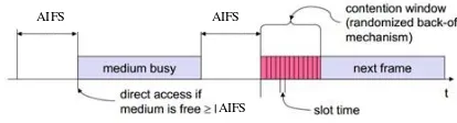
There are three main parameters for QoS adjustment in EDCA as describe in Fig. 1
a. Transmission Opportunity (TXOP) is period for station for sending packet
b. Arbitration Inter-Frame Space (AIFS) is space time after station sending packet
c. Contention Window (CW) is back-off timer after AIFS before station sending packet or a frame. If medium is idle than CW could be set to zero for immediate sending. Number of CW is range between CWmin and CWmax
AIFS AIFS
AIFS
Fig 1. Three parameters in EDCA
IEEE 802.11 DCF standard is enhanced by EDCA scheme using back-off timer with different value for each Access Category. Each Access Category has a specific Contention Window. A contention window is a period of time when mobile node has a legitimate access to send packet to media. A contention window has a range from a specific value until a maximum time. If transmission is unsuccessful the contention window is set to larger value.
In DCF scheme, contention window is stopped when the media is not idle and decreased when the media is idle during one AIFS. The media is considered not idle when there is unsuccessful packet transmission. Unsuccessful packet transmission occurs when there is a collision. Collision can consist of two model i.e internal or virtual collision and external collision. Internal collision occurs when among packet in the same mobile node is sent simultaneously. External collision occurs when packet from different mobile node is sent simultaneously into media [5]. Internal collision refer to collision between packets in different application..
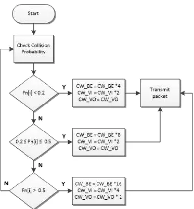
number of station involved and collision probability. The flow chart of modification is shown in Fig.2. As per described previously, there are two important parameters that govern Wifi client access to the shared channel under the EDCA, the AIFS
𝜌
= 1
−
1
−
1
𝑊
����𝑔𝑛−1
and the CW. Similar to channel access under the DCF, the AIFS is a fixed waiting period, whereas the CWmin defines a range from which a random waiting time is selected.
For higher priority traffic such as video and voice call, CWmax - CWmin should have small difference. If the difference is large than delay will go higher. In high load traffic, it is recommended to drop the packet because it could be a very long time for the packet to wait the opportunity. This method is important for delay sensitive packet such as video and voice call. When the contention window is small, probability to send packet is higher and delay become small. But, a small CW also affect to higher collision probability. If contention window is large, overall throughput will be decreased [8]. When the number of higher priority packet increase, CW difference become smaller. This is a result of more collisions between packets in high priority traffic. Small CWmin also has a significant impact to AIFS value. Setting a small contention window is a better method to have good throughput for higher priority traffic but will have a bad effect to lower priority traffic.
Fig. 2 Adaptive Contention Window algorithm
Let’s say the initial contention window value is W. If ρ is value of collision probability, arbitrary packet can be successfully transmitted with probability 1 – ρ. The average back-off window from this condition is (W − 1)/2. When mobile node fail to send packet in the first attempt, the mobile node will send the packet in second attempt with probability ρ (1 −ρ). In this condition, the average backoff window is (2W − 1)/2. This method can be used for the last (kth) permitted attempt. The backoff window will increase until reach the CWmax value.
The collision probability ρ can be measured with the following formula [9]:
Throughput and delay performance depends on the number of nodes in the network with the initial value of contention window. If the number of nodes increase, the throughput will decrease significantly for given contention window size. It can be said also that maximum throughput depends on the value of CWmin for the specific number of nodes. A small contention window in the initial cycle of packet transmission usually impact to high collision probability, especially if the number of nodes is large.
This algorithm is implemented in the network simulator and performed iterations to obtain the optimal parameters. If there is improvement result than previous methods, as measured by throughput means algorithm modifications are done successfully. Simulations carried out in several scenarios, namely the network saturation and non-saturation to obtain the optimal parameters. Simulations will be performed by the user maximum number of 45 stations by changing contention window value at each access category to get the throughput and collision in each condition.
IV. SYSTEM MODELLING AND SIMULATION PROCESS
Proposed network topology used for this simulation is describe in Figure 3. The topology divide into two parts. The first part is wireless which is consist of QSTA and QAP. The second part is wired which is consist of router and servers. The number of stations that will be used for the simulation is 45 station with the kind of traffic that is:
a. Real time traffic : VOIP using codec G711 with rate 64 kbps (UDP packet)
b. Semi real time traffic : video streaming with rate 384 kbps (RTP packet)
c. Non real time traffic : FTP (best effort) with 1 Mbps generator (TCP packet)
Fig 3. Network Topology for Simulation
EDCA module. Non-saturated system is normal environment when total traffic is less than 802.11g maximum capacity. In this simulation maximum data rate configured in the QAP is 18 Mbps. Every single QSTA can deliver data without any packet dropping. Packet scheduler is still required to eliminate collision during transmission. Saturated system is occurred when heavy load traffic generated in the network above the capacity of 802.11g maximum throughput. Beside the packet scheduler, packet dropping for the low priority data is required to decrease the network load.
The following assumptions for analysis and simulation [6]: a. There are three ACs in the simulation: AC A, AC B and AC
C with CW [A] < CW [B] < CW [C].
b. Every mobile node send one type of traffic. AC A will send voice traffic, AC B will send video traffic, AC C will send FTP traffic.
c. One TXOP consist of one frame only (Transmission Opportunity).
d. Each QSTA communicate to destination server directly. e. In one simulation the number of mobile nodes are fixed. f. Collision probability of a mobile node is considered constant
in a specific time slot. g. The wireless channel is ideal.
In NS-2 implementation, it is considered a network scenario called wireless-cum. It consist of Basic Service Set (BSS) with an Access Point and 45 mobile nodes. A dedicated Servers are connected to Access Point via a router. Link between router and server is set to 100 Mbps. It is considered also no delay and no packet drop during simulation between router and servers. There is no hidden stations in the wireless network. Mobile node can directly connect to server via AP using protocol DSDV. Access Point physical layer uses 802.11g with data rate is set to 18 Mbps.
Traffic will be sent from mobile node to server for each type of traffic. Voice call will be sent from mobile node to VOIP Server, video will be sent from mobile node to Video Server and data traffic will be sent from mobile node to FTP Server. This system topology create a wired-cum-wireless topology since multiple LAN connected to wireless network via a router and an access point. Basic Station Node is used as gateway of wireless domain. This device is responsible to deliver packets into and out of wireless domain. Router is used as gateway of wired domain.
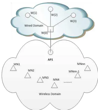
For simulations the topology needs to use hierarchical routing in order to route packets between wireless and wired domains as describe in Fig. 4 [4]. The routing information for wired nodes are based on connectivity of the topology where W(0) is router, W(1) is VOIP Server, W(2) is Video Server, W(3) is FTP Server, AP is Access Point and MN is mobile node (client). This connectivity information is used to populate the forwarding tables in each wired node. However wireless nodes have no concept of links. Packets are routed in a wireless topology using their ad hoc routing protocols which build forwarding tables by exchanging routing queries among its neighbors. So in order to exchange packets among these wired and wireless nodes, base-stations is used which act as gateways
between the two domains. To segregate wireless and wired domain, the device is put in different domains.
Fig 4. Wired - Wireless Topology for Simulation
It is a mandatory that base station must be in the same domain with the mobile node. All packet from servers in wired domain will be sent to mobile node via router then access point using a specific routing which has been defined in the initial configuration. In one simulation it will involve wired node and wireless nodes. It is necessary to turn on hierarchical routing, to make different domains for wireless and wired node and to setup an access point in every wireless domain. This access point is the gateway for mobile nodes to communicate with other device in other domain.
If a simulation finish, awk script is used to analyze the trace file collected during simulation [10]. This awk script calculates throughput and delay performance for low priority and high priority traffic. Delay is calculated as the difference between packet received in the destination and the time packet sent from the source. Throughput is calculated as the number of byte received compared with the time of simulation.
15.00% 13.00% 11.00% 9.00% 7.00% 5.00% 3.00% 1.00% -1.00%
1 2 3 4 5 6 7 8 9 10 11 12 13 14 15
T
hr
ou
g
hpu
t
(M
bp
s)
D
e
lay
(
%
)
meets the purpose, the total throughput and delay obtained is evaluated for different numbers of stations.
In simulation, there was one QoS Access Point (QAP) which connected to one mobile node or wireless QoS Stations (QSTAs). QAP and QSTA are device that capable delivering QoS standard as mention in 802.11e. Traffic source is sent from QSTAs. The QAP also connected to three static station via router by a 100 Mbps Ethernet link. The destination station served as a sink which received the traffic generated from all of the QSTAs.
Proposed Research Throughput
12 10 8 6 4 2 0
1 2 3 4 5 6 7 8 9 10 11 12 13 14 15
Number of QSTA
AC_VOIP AC_Video AC_FTP
Fig 5. Throuhput performance per AC
Fig 6. Delay Performance per AC
Fig 7. Throughput Improvement
Detail throughput improvement percentage can be summarized in table 2.
Table 2. Throughput Improvement per AC
Fig. 8 shows the average of the delay improvement with 3.32% value. During saturated network, throughput average improvement for all traffic is 5.48%. VOIP has the highest level with 13.46% improvement. It can be considered that there is no delay improvement in FTP network.
Delay Improvement Percentage
Fig. 5 shows the throughput performance per traffic. The throughput increase linearly with the number of QSTA set during the simulation. But after reaching around 30 stations, the slope decrease. It shows that the network has been overloaded by traffic and tend to be saturated. It occurs in the same way for
-3.00%
Number of QSTA
VOIP Improvement Video Improvement FTP Improvement
Fig 8. Throughput Improvement
the delay, as described in Fig. 6. If the network is saturated, the delay result is higher.
Fig. 7 shows the average of throughput improvement with 2.46% value. Saturated network is consider in the condition when network is loaded with heavy traffic. This condition occur when the number of QSTA is 11 to 15. During saturated condition throughput average improvement for all traffic is 3.69%. VOIP has highest level with 7.89% improvement. It can be considered that there is no throughput improvement in FTP network.
Detail delay improvement percentage can be summarize in table 3.
very small improvement during low traffic and considered no
improvement during saturated traffic. [5] G. Prakash and P. Thangaraj, 802.11e EDCA and 802.11b DCF under Non Saturation “Performance Comparison of IEEE There are some benefits of the propose algorithm. First, the Condition using Network Simulator”, Research Journal of collision among packet transmitted at the same priority become Applied Sciences, Engineering and Technology 4(22): 4748- small especially for high priority traffic such as video and voice 4754, 2012
call. Second, it gives a low delay and high throughput. Third, it [6] Lixiang Xiong, “A Markov Chain Approach to IEEE 802.11 gives high throughput for real time traffic as well as gives a
smaller delay for video and voice call. The proposed method
WLAN Performance Analysis”, School of Electrical & Information Engineering The University of Sydney, 2008 gives improvement to overall network performance [7] Navid Tadayon and Saadan Zokaei, “Introducing an Adaptive
Method to Tune Initial Backoff Window (CWmin-ATM) in IEEE 802.11 Wireless Networks”, Hindawi Publishing Corporation
ACKNOWLEDGMENT EURASIP Journal on Wireless Communications and Networking
VI. CONCLUSION
Simulation is used to investigate the throughput and delay performance of the new WLAN standard IEEE 802.11e and compare it with the previous research algorithm. Simulation experiments are performed using an infrastructure wireless network under different type of traffic and load of traffic. The traffic mix is changed by varying the number of station sending the different type of traffic.
Based on EDCA previous research algorithm with modification of contention window mechanism, the proposed algorithm leads the throughput improvement by 2.29% and delay improvement by 3.32% in average for all traffic category. During saturated network the throughput improvement is 3.69% and delay improvement by 5.48%. VOIP traffic gets the highest improvement for all condition of traffic. Best effort traffic gets
REFERENCES
[1] Rathnakar Achary, V. Vaithiyanathan, Pethur Raj, Nagarajan S "Performance Enhancement of IEEE 802.11e WLAN by Dynamic Adaptive Contention Window" School of Computing SASTRA University, India, 16th International Conference of Advanced Communication Technology (ICACT) 2014
[2] Y. Lee "Throughput Analysis Model for IEEE 802.11e EDCA with Multiple Access Categories" Department of Information and Communication Engineering, Dongeui University, Journal of Applied Research and Technology 2013
[3] Marcus Burton “802.11 Arbitration” CWNE #78 CWNP, Inc, White Paper
[4] Lassaad Gannoune, Stephan Robert and Daniel Rodellar “A Survey of QoS Technique sand Enhancements for IEEE 802.11 Wireless LANs”, Broadband Network Ebook, Swisscom Switzerland
This work is fully funded by Master Degree Scholarship of PT Telekomunikasi Indonesia Tbk in Telkom University Bandung.
Volume 2010
[8] Anni Matinlauri, “Fairness and Transmission Opportunity Limit in IEEE 802.11e Enhanced Distributed Channel Access”, Department of Electrical and Communications Engineering Helnsinky University of Technology, 2008
[9] Hai L. Vu and Taka Sakurai, “Collision Probability in Saturated IEEE 802.11 Networks”, Centre for Advanced Internet Architectures (CAIA) ICT Faculty, Swinburne University of Technology Hawthorn, VIC 3122, Australia