CompTIA Network+: Exam N10-005
Objective chapter
1.0 NetwOrk cONcepts (21 perceNt)
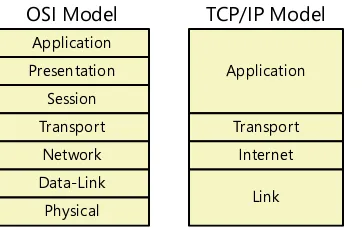
1.1 Compare the layers of the OSI and TCP/IP models: OSI model (Layer 1 – Physical, Layer 2 – Data link, Layer 3 – Network, Layer 4 – Transport, Layer 5 – Session, Layer 6 – Presentation, Layer 7 – Applica-tion); TCP/IP model (Network Interface Layer, Internet Layer, Transport Layer, Application Layer [Also described as: Link Layer, Internet Layer, Transport Layer, Application Layer])
1
1.2 Classify how applications, devices, and protocols relate to the OSI model layers: MAC address; IP address; EUI-64; Frames; Packets; Switch; Router; Multilayer switch; Hub; Encryption devices; Cable; NIC; Bridge
1, 3, 6, 7
1.3 Explain the purpose and properties of IP addressing: Classes of addresses (A, B, C and D, Public vs. Private); Classless (CIDR); IPv4 vs. IPv6 (formatting); MAC address format; Subnetting; Multicast vs. unicast vs. broadcast; APIPA
6
1.4 Explain the purpose and properties of routing and switching: EIGRP; OSPF; RIP; Link state vs. distance vector vs. hybrid; Static vs. dynamic; Routing metrics (Hop counts, MTU, bandwidth, Costs, Latency); Next hop; Spanning-Tree Protocol; VLAN (802.1q); Port mirroring; Broadcast domain vs. collision domain; IGP vs. EGP; Routing tables; Convergence (steady state)
7
1.5 Identify common TCP and UDP default ports: SMTP – 25; HTTP – 80; HTTPS – 443; FTP – 20, 21; TELNET – 23; IMAP – 143; RDP – 3389; SSH – 22; DNS – 53; DHCP – 67, 68
8 1.6 Explain the function of common networking protocols: TCP; FTP; UDP; TCP/IP suite; DHCP; TFTP;
DNS; HTTPS; HTTP; ARP; SIP (VoIP); RTP (VoIP); SSH; POP3; NTP; IMAP4; Telnet; SMTP; SNMP2/3; ICMP; IGMP; TLS
4, 6, 8, 9, 12
1.7 Summarize DNS concepts and its components: DNS servers; DNS records (A, MX, AAAA, CNAME, PTR); Dynamic DNS
9 1.8 Given a scenario, implement the following network troubleshooting methodology: Identify the
problem (Information gathering, Identify symptoms, Question users, Determine if anything has changed); Establish a theory of probable cause (Question the obvious); Test the theory to deter-mine cause (Once theory is confirmed deterdeter-mine next steps to resolve problem; If theory is not confirmed, re-establish new theory or escalate); Establish a plan of action to resolve the problem and identify potential effects; Implement the solution or escalate as necessary; Verify full system functionality and if applicable implement preventative measures; Document findings, actions and outcomes
13
1.9 Identify virtual network components: Virtual switches; Virtual desktops; Virtual servers; Virtual PBX; Onsite vs. offsite; Network as a Service (NaaS)
12 2.0 NetwOrk iNstaLLatiON aND cONFiGUratiON (23 perceNt)
2.1 Given a scenario, install and configure routers and switches: Routing tables; NAT; PAT; VLAN (trunk-ing); Managed vs. unmanaged; Interface configurations (Full duplex, Half duplex, Port speeds, IP addressing, MAC filtering); PoE; Traffic filtering; Diagnostics; VTP configuration; QoS; Port mirroring
7
2.2 Given a scenario, install and configure a wireless network: WAP placement; Antenna types; Inter-ference; Frequencies; Channels; Wireless standards; SSID (enable/disable); Compatibility (802.11 a/b/g/n)
5
2.3 Explain the purpose and properties of DHCP: Static vs. dynamic IP addressing; Reservations; Scopes;
Leases; Options (DNS servers, suffixes) 9
2.4 Given a scenario, troubleshoot common wireless problems: Interference; Signal strength; Config-urations; Incompatibilities; Incorrect channel; Latency; Encryption type; Bounce; SSID mismatch; Incorrect switch placement
13
2.5 Given a scenario, troubleshoot common router and switch problems: Switching loop; Bad cables/ improper cable types; Port configuration; VLAN assignment; Mismatched MTU/MTU black hole; Power failure; Bad/missing routes; Bad modules (SFPs, GBICs); Wrong subnet mask; Wrong gateway; Duplicate IP address; Wrong DNS
13
2.6 Given a set of requirements, plan and implement a basic SOHO network: List of requirements; Cable length; Device types/requirements; Environment limitations; Equipment limitations; Compat-ibility requirements
Objective chapter 3.0 NetwOrk meDia aND tOpOLOGies (17 perceNt)
3.1 Categorize standard media types and associated properties: Fiber (Multimode, Singlemode); Cop-per (UTP, STP, CAT3, CAT5, CAT5e, CAT6, CAT6a, Coaxial, Crossover, T1 Crossover, Straight-through); Plenum vs. non-plenum; Media converters (Singlemode fiber to Ethernet, Multimode fiber to Eth-ernet, Fiber to Coaxial, Singlemode to multimode fiber); Distance limitations and speed limitations; Broadband over powerline
2
3.2 Categorize standard connector types based on network media: Fiber (ST, SC, LC, MTRJ); Copper (RJ-45, RJ-11, BNC, F-connector, DB-9 [RS-232], Patch panel, 110 block [T568A, T568B])
2 3.3 Compare and contrast different wireless standards: 802.11 a/b/g/n standards (Distance, Speed,
Latency, Frequency, Channels, MIMO, Channel bonding)
5 3.4 Categorize WAN technology types and properties: Types (T1/E1, T3/E3, DS3, OCx, SONET, SDH,
DWDM, Satellite, ISDN, Cable, DSL, Cellular, WiMAX, LTE, HSPA+, Fiber, Dialup, PON, Frame relay, ATMs); Properties (Circuit switch, Packet switch, Speed, Transmission media, Distance)
10
3.5 Describe different network topologies: MPLS; Point to point; Point to multipoint; Ring; Star; Mesh; Bus; Peer-to-peer; Client-server; Hybrid
2 3.6 Given a scenario, troubleshoot common physical connectivity problems: Cable problems (Bad
connectors; Bad wiring; Open; short; Split cables; DB loss; TXRX reversed; Cable placement; EMI/ Interference; Distance; Cross-talk)
2, 13
3.7 Compare and contrast different LAN technologies: Types (Ethernet, 10BaseT, 100BaseT, 1000BaseT, 100BaseTX, 100BaseFX, 1000BaseX, 10GBaseSR, 10GBaseLR, 10GBaseER, 10GBaseSW, 10GBaseLW, 10GBaseEW, 10GBaseT); Properties (CSMA/CD, CSMA/CA, Broadcast, Collision, Bonding, Speed, Distance)
4
3.8 Identify components of wiring distribution: IDF, MDF, Demarc, Demarc extension, Smart jack, CSU/ DSU
2 4.0 NetwOrk maNaGemeNt (20 perceNt)
4.1 Explain the purpose and features of various network appliances: Load balancer; Proxy server;
Con-tent filter; VPN concentrator 12
4.2 Given a scenario, use appropriate hardware tools to troubleshoot connectivity issues: Cable tester; Cable certifier; Crimper; Butt set; Toner probe; Punch down tool; Protocol analyzer; Loop back plug; TDR; OTDR; Multimeter; Environmental monitor
2
4.3 Given a scenario, use appropriate software tools to troubleshoot connectivity issues: Protocol ana-lyzer; Throughput testers; Connectivity software; Ping; Tracert/traceroute; Dig; Ipconfig/ifconfig; Nslookup; Arp; Nbtstat; Netstat; Route
13
4.4 Given a scenario, use the appropriate network monitoring resource to analyze traffic: SNMP;
SNMPv2; SNMPv3; Syslog; System logs; History logs; General logs; Traffic analysis; Network sniffer 12 4.5 Describe the purpose of configuration management documentation: Wire schemes; Network maps;
Documentation; Cable management; Asset management; Baselines; Change management
12 4.6 Explain different methods and rationales for network performance optimization: Methods (QoS,
Traffic shaping, Load balancing, High availability, Caching engines, Fault tolerance, CARP); Reasons (Latency sensitivity, High bandwidth applications [VoIP, video applications, unified communica-tions], Uptime)
12
5.0 NetwOrk secUritY (19 perceNt)
5.1 Given a scenario, implement appropriate wireless security measures: Encryption protocols (WEP, WPA, WPA2, WPA Enterprise); MAC address filtering; Device placement; Signal strength 11 5.2 Explain the methods of network access security: ACL (MAC filtering, IP filtering, Port filtering);
Tunneling and encryption (SSL VPN, VPN, L2TP, PPTP, IPSec, ISAKMP, TLS, TLS2.0, Site-to-site and client-to-site); Remote access (RAS, RDP, PPPoE, PPP, ICA, SSH)
4, 10, 11
5.3 Explain methods of user authentication: PKI; Kerberos; AAA (RADIUS, TACACS+); Network access control (802.1x, posture assessment); CHAP; MS-CHAP; EAP; Two-factor authentication; Multifactor authentication; Single sign-on
11
5.4 Explain common threats, vulnerabilities, and mitigation techniques: Wireless (War driving, War chalking, WEP cracking, WPA cracking, Evil twin, Rogue access point); Attacks (DoS, DDoS, Man in the middle, Social engineering, Virus, Worms, Buffer overflow, Packet sniffing, FTP bounce, Smurf); Mitigation techniques (Training and awareness, Patch management, Policies and procedures, Incident response)
11
5.5 Given a scenario, install and configure a basic firewall: Types (Software and hardware firewalls); Port security; Stateful inspection vs. packet filtering; Firewall rules (Block/allow, Implicit deny, ACL); NAT/ PAT; DMZ
CompTIA Network+
Exam N10-005
Training Kit
Published with the authorization of Microsoft Corporation by:
O’Reilly Media, Inc.
1005 Gravenstein Highway North Sebastopol, California 95472
Copyright © 2012 by Craig Zacker
All rights reserved. No part of the contents of this book may be reproduced or transmitted in any form or by any means without the written permission of the publisher.
ISBN: 978-0-7356-6275-9
1 2 3 4 5 6 7 8 9 QG 7 6 5 4 3 2
Printed and bound in the United States of America.
Microsoft Press books are available through booksellers and distributors worldwide. If you need support related to this book, email Microsoft Press Book Support at [email protected]. Please tell us what you think of this book at http://www.microsoft.com/learning/booksurvey.
Microsoft and the trademarks listed at http://www.microsoft.com/about/legal/ en/us/IntellectualProperty/Trademarks/EN-US.aspx are trademarks of the Microsoft group of companies. All other marks are property of their respec-tive owners.
The example companies, organizations, products, domain names, email
ad-dresses, logos, people, places, and events depicted herein are fictitious. No
association with any real company, organization, product, domain name, email address, logo, person, place, or event is intended or should be inferred.
This book expresses the author’s views and opinions. The information con-tained in this book is provided without any express, statutory, or implied warranties. Neither the authors, O’Reilly Media, Inc., Microsoft Corporation, nor its resellers, or distributors will be held liable for any damages caused or alleged to be caused either directly or indirectly by this book.
acquisitions and Developmental editors: Ken Jones, Kenyon Brown
production editor: Holly Bauer
editorial production: Online Training Solutions, Inc.
technical reviewers: Dan Tuuri, Brian Blum
copyeditor: Kathy Krause, Online Training Solutions, Inc.
indexer: Angela Howard
cover Design: Twist Creative • Seattle cover composition: Karen Montgomery
Contents at a Glance
Introduction
xix
ChApTEr 1 Networking Basics 1
ChApTEr 2 The physical Layer 43
ChApTEr 3 Network Devices 101
ChApTEr 4 The Data-Link Layer 141
ChApTEr 5 Wireless Networking 191
ChApTEr 6 The Network Layer 229
ChApTEr 7 routing and Switching 291
ChApTEr 8 The Transport Layer 339
ChApTEr 9 The Application Layer 369
ChApTEr 10 Wide Area Networking 445
ChApTEr 11 Network Security 483
ChApTEr 12 Network Management 541
ChApTEr 13 Network Troubleshooting 583
Glossary
637
Index
655
What do you think of this book? We want to hear from you!
Contents
introduction xix
System Requirements xix
Using the Companion CD xx
Support & Feedback xxi
Preparing for the Exam xxii
chapter 1 Networking basics
1
Network Communications . . . 2
LANs and WANs 3
Signals and Protocols 5
Packet Switching and Circuit Switching 8
Client/Server and Peer-to-Peer Networks 9
The OSI Reference Model . . . 10
Protocol Interaction 12
Data Encapsulation 13
The Physical Layer 16
The Data-Link Layer 18
The Network Layer 22
The Transport Layer 25
The Session Layer 29
The Presentation Layer 31
The TCP/IP Model . . . 34
The Link Layer 35 The Internet Layer 36 The Transport Layer 36 The Application Layer 37 Exercise . . . 37
Chapter Summary . . . 38
Chapter Review . . . 39
Answers . . . 40
Exercise 40 Chapter Review 40
chapter 2 the physical Layer
43
Cables and Connectors . . . 45Copper Cable Types 46 Fiber Optic Cable 55 Power Line Networking 57 Media Converters 58 Topologies and Tools . . . 59
Cable Topologies 59 Multiprotocol Label Switching 67 Cabling Standards 68 Installing Cables . . . 70
Installing External Cables 70 Installing Internal Cables 73 Connecting to the Backbone . . . 92
Exercise . . . 96
Chapter Summary . . . 97
Chapter Review . . . 98
chapter 3 Network Devices
101
Network Interface Adapters . . . 103
Network Interface Adapter Functions 108 Optional Network Adapter Functions 109 Purchasing Network Interface Adapters 112 Installing a Network Interface Adapter 114 Troubleshooting a Network Interface Adapter 116 At the Other End of the Cable . . . 117
Using Repeaters 117 Using Hubs 118 Using Bridges 122 Using Routers 124 Using Switches 129 Using Multifunction Devices 135 Exercise . . . 136
Chapter Summary . . . 137
Chapter Review . . . 138
Answers . . . 139
Exercise 139 Chapter Review 139
chapter 4 the Data-Link Layer
141
Ethernet . . . 143Ethernet Standards 143 Ethernet Components 145 Point-to-Point Protocol (PPP) . . . 169
PPP Standards 170
The PPP Frame 171
Authentication Protocols 175
The IPCP Frame 176
Address Resolution Protocol (ARP) . . . 180
ARP Message Format 181 ARP Transactions 183 Exercise . . . 185
Chapter Summary . . . 186
Chapter Review . . . 188
Answers . . . 189
Exercise 189 Chapter Review 190
chapter 5 wireless Networking
191
Wireless LAN Standards . . . 192Building a Wireless Standard 193 IEEE 802.11 Standards 194 Wireless LAN Architecture. . . 201
The Physical Layer 201 The Data-Link Layer 210 Installing a Wireless LAN . . . 215
Examining the Site 215 Selecting Hardware 217 Installing and Configuring Wireless Hardware 222 Exercise . . . 224
Chapter Summary . . . 224
Chapter Review . . . 225
Answers . . . 226
Exercise 226 Chapter Review 226
chapter 6 the Network Layer
229
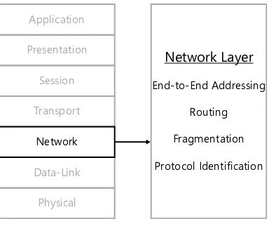
Internet Protocol (IP) . . . 230IPv4 Addressing . . . 234
IPv4 Address Assignments 235
IPv4 Address Classes 236
IPv4 Address Types 237
Subnet Masking 238
Classless Inter-Domain Routing 243
Registered and Unregistered Addresses 245
Obtaining IP Addresses 247
Assigning IPv4 Addresses 248
IPv6 Addressing . . . 250
IPv6 Address Types 251
IPv6 Address Assignment 260
Data Encapsulation . . . 262
The IPv4 Datagram Format 264
The IPv6 Datagram Format 268
IPv4 Fragmentation 271
IPv6 Fragmentation 272
IP Routing 273
Internet Control Message Protocol (ICMP) . . . 273
ICMPv4 273
ICMPv6 280
Internet Group Management Protocol (IGMP) . . . 283
Exercises . . . 285
Scenario #1 285
Scenario #2 285
Chapter Summary . . . 286
Chapter Review . . . 287
Answers . . . 288
Exercises 288
chapter 7 routing and switching
291
Routing . . . 293
What Is Routing? 293
Router Functions 294
Router Products 297
Understanding Routing Tables 298
Routing in IPv6 308
Routing and ICMP 308
Routing and Network Address Translation 309
Static and Dynamic Routing 313
Switching . . . 327
Routing vs. Switching 328
Configuring VLAN Trunking Protocol (VTP) 332
Power Over Ethernet (PoE) 333
Exercises . . . 334
Scenario #1 334
Scenario #2 334
Chapter Summary . . . 335
Chapter Review . . . 336
Answers . . . 337
Exercises 337
Chapter Review 337
chapter 8 the transport Layer
339
Transmission Control Protocol (TCP) . . . 341
The TCP Header 341
TCP Options 343
TCP Communications 345
User Datagram Protocol (UDP) . . . 358
Ports and Sockets . . . 360
Chapter Review . . . 364
Answers . . . 366
Exercise 366
Chapter Review 366
chapter 9 the application Layer
369
Application Layer Communications . . . 370
DHCP . . . 370
DHCP Origins 371
DHCP Objectives 372
IP Address Assignment 374
Creating Scopes 375
TCP/IP Client Configuration 375
DHCP Packet Structure 376
DHCP Options 378
DHCP Communications 380
Relay Agents 388
DHCPv6 389
DNS 395
Host Tables 395
DNS Objectives 396
Domain Naming 398
Resource Records 404
DNS Messaging 405
DNS Name Resolution 406
Reverse Name Resolution 412
DNS Name Registration 414
Zone Transfers 416
HTTP . . . 417
HTTP Requests 418
HTTP Responses 419
FTP . . . 422
FTP Commands 423 FTP Messaging 424 TFTP . . . 426
Telnet . . . 426
Email . . . 427
Email Addressing 428 Email Clients and Servers 428 SMTP 430 POP3 433 IMAP 435 NTP . . . 436
Exercise . . . 439
Chapter Summary . . . 439
Chapter Review . . . 441
Answers . . . 442
Exercise 442 Chapter Review 442
chapter 10 wide area Networking
445
What Is a WAN? . . . .446Connecting to the Internet . . . .448
Public Switched Telephone Network 448 Integrated Services Digital Network (ISDN) 450 Digital Subscriber Line (DSL) 452 Cable Television (CATV) Networks 454 Satellite-Based Services 455 Last Mile Fiber 456 Cellular Technologies 457 Connecting LANs . . . 459
Remote Access . . . 468
Dial-up Remote Access 469 Virtual Private Networking 470 SSL VPN 475 Using a VPN Concentrator 475 Remote Terminal Emulation 475 Exercise . . . 477
Chapter Summary . . . 477
Chapter Review . . . 479
Answers . . . 480
Exercise 480 Chapter Review 480
chapter 11 Network security
483
Authentication and Authorization . . . 485Network Authentication Systems 486 Authentication Protocols 493 Tunneling and Encryption Protocols . . . 501
IPsec 501 SSL and TLS 507 Wireless Security Protocols . . . 509
WEP 509 802.1X 511 WPA 512 Other Wireless Security Techniques 513 Firewalls . . . 515
Packet Filtering 516
Stateful Packet Inspection 520
Firewall Implementations 521
Creating a Peripheral Network 525
Security Threats . . . 528
Denial of Service 529 Man in the Middle 529 Malware 530 Buffer Overflow 531 Social Engineering 531 Wireless Threats 532 Mitigation Techniques 533 Exercise . . . 534
Chapter Summary . . . 535
Chapter Review . . . 536
Answers . . . 538
Exercise 538 Chapter Review 538
chapter 12 Network management
541
Network Documentation . . . 542Cable Diagrams 543 Network Diagrams 544 Network Maps 546 Hardware Configurations 546 Change Management 547 Baselines 547 Network Monitoring . . . 549
Logs 549
SNMP 556
Protocol Analyzers 558
Port Scanners 563
Virtualization . . . 566
Virtualization Architectures 567 Desktop Virtualization 569 Virtual Switching 570 Presentation Virtualization 570 Application Virtualization 571 Virtual PBXes 571 Performance Optimization . . . 572
Caching Data 573 Traffic Control 574 Redundant Services 575 Exercise . . . 578
Chapter Summary . . . 579
Chapter Review . . . 580
Answers . . . 581
Exercise 581 Chapter Review 581
chapter 13 Network troubleshooting
583
Troubleshooting Tools . . . 585The Ping Program 585
Traceroute 586
Ifconfig and Ipconfig.exe 588
ARP 589
Netstat 590
Nbtstat.exe 594
Nslookup 595
Dig 596
Route 597
Troubleshooting Methodology . . . 597
Identify the Problem 598 Establish a Theory 601 Test the Theory 601 Establish a Plan of Action 602 Implement the Solution 603 Verify System Functionality 603 Document Findings 604 Troubleshooting Connectivity Issues 605 Troubleshooting Wireless Problems 606 Troubleshooting Router and Switch Problems 607 Network Troubleshooting Scenario: “I Can’t Access a Website” . . . 612
Incident Administration 612 Gathering Information 613 Possible Cause: Internet Router Problem 614 Possible Cause: Internet Communication Problem 616 Possible Cause: DNS Failure 617 Possible Cause: LAN Communications Problem 622 Possible Cause: Computer Configuration Problem 626 Possible Cause: User Error 630 Exercise . . . 631
Chapter Summary . . . 631
Chapter Review . . . 632
Answers . . . 634
Exercise 634
Chapter Review 634
Glossary 637
Introduction
This training kit is designed for information technology (IT) professionals who support or plan
to support networks and who also plan to take the CompTIA Network+ exam. It is assumed that before you begin using this kit, you have a CompTIA A+ certification or the equivalent
knowledge, as well as 9 to 12 months of work experience in IT networking.
The material covered in this training kit and on the Network+ exam relates to the technol -ogies in a network that support distributed access to web content, media, operating systems, and applications. The topics in this training kit cover what you need to know for the exam as
described on the Certification Exam Objectives document for the exam, which is available at:
http://certification.comptia.org/getCertified/certifications/network.aspx
By using this training kit, you will learn how to do the following:
■ Use the Open Systems Interconnection (OSI) reference model to understand network processes.
■ Install and maintain the various cables and other media used to build networks.
■ Understand the protocols that networked computers use to communicate.
■ Understand how routers and switches connect network devices to each other and to other networks.
■ Connect to distant networks by using wide area network (WAN) technologies.
■ Secure a network by using firewalls and other tools.
■ Use network monitoring and diagnostic tools.
■ Troubleshoot network problems in a systematic and logical manner.
Refer to the objective mapping page in the front of this book to see where in the book each exam objective is covered.
system requirements
CompTIA suggests you have access to various hardware and software to help you prepare for
the Network+ exam. The items include equipment, spare hardware, spare parts, tools, soft
-ware, and other items you might need. You’ll find a list of items at the back of the CompTIA Network+ Certification Exam Objectives: N10-005 guide, which you can download from
Using the companion cD
A companion CD is included with this training kit. The companion CD contains the following:
■ practice tests You can reinforce your understanding of the topics covered in this training kit by using electronic practice tests that you customize to meet your needs.
You can practice for the Network+ certification exam by using tests created from a
pool of 200 realistic exam questions, which give you many practice exams to ensure that you are prepared.
■ an ebook An electronic version (eBook) of this book is included for when you do not want to carry the printed book with you.
Note cOmpaNiON cONteNt FOr DiGitaL bOOk reaDers
If you bought a digital-only edition of this book, you can enjoy select content from the print edition’s companion CD. Visit http://go.microsoft.com/FWLink/?Linkid=248373 to get your downloadable content.
how to Install the practice Tests
To install the practice test software from the companion CD to your hard disk, perform the following steps:
1. Insert the companion CD into your CD drive and accept the license agreement. A CD menu appears.
Note iF the cD meNU DOes NOt appear
If the CD menu or the license agreement does not appear, Autorun might be disabled
on your computer. Refer to the Readme.txt file on the CD for alternate installation
instructions.
how to Use the practice Tests
To start the practice test software, follow these steps:1. Click Start, All Programs, and then select Microsoft Press Training Kit Exam Prep.
2. A window appears that shows all the Microsoft Press training kit exam prep suites installed on your computer.
3. Double-click the practice test you want to use.
When you start a practice test, you choose whether to take the test in Certification Mode,
Study Mode, or Custom Mode:
■ Certification Mode Closely resembles the experience of taking a certification exam. The test has a set number of questions. It is timed, and you cannot pause and restart the timer.
■ study mode Creates an untimed test during which you can review the correct an-swers and the explanations after you answer each question.
■ custom mode Gives you full control over the test options so that you can customize them as you like.
In all modes, the user interface when you are taking the test is basically the same but with different options enabled or disabled depending on the mode.
When you review your answer to an individual practice test question, a “References” sec
-tion is provided that lists where in the training kit you can find the informa-tion that relates to
that question. After you click Test Results to score your entire practice test, you can click the Learning Plan tab to see a list of references for every objective.
how to Uninstall the practice Tests
To uninstall the practice test software for a training kit, use the Programs And Features option in Control Panel.
support & Feedback
Errata & Book Support
We’ve made every effort to ensure the accuracy of this book and its companion content. Any
errors that have been reported since this book was published are listed on our Microsoft Press site at oreilly.com:
http://go.microsoft.com/FWLink/?Linkid=248372
If you find an error that is not already listed, you can report it to us through the
same page.
If you need additional support, email Microsoft Press Book Support at:
Please note that product support for Microsoft software is not offered through the addresses above.
We Want to hear from You
At Microsoft Press, your satisfaction is our top priority, and your feedback is our most valuable asset. Please tell us what you think of this book at:
http://www.microsoft.com/learning/booksurvey
The survey is short, and we read every one of your comments and ideas. Thanks in advance for your input!
Stay in Touch
Let’s keep the conversation going! We are on Twitter: http://twitter.com/MicrosoftPress.
preparing for the exam
CompTIA certification exams are a great way to build your resume and let the world know about your level of expertise. Certification exams validate your on-the-job experience and
product knowledge. Although there is no substitute for on-the-job experience, preparation
through study and hands-on practice can help you prepare for the exam. We recommend
that you augment your exam preparation plan by using a combination of available study materials and courses. For example, you might use the Training Kit and another study guide
for your “at home” preparation, and take a CompTIA professional certification course for the
c h a p t e r 1
Networking Basics
T
his chapter introduces the fundamental computer network-ing concepts that form the basis for all of the questions onthe CompTIA Network+ examination. You might be inclined to
skip around in this book during your exam preparation regimen, but you should make sure that you understand the principles in
this chapter before you do so. Otherwise, you might find your -self struggling later, both in the exam room and on the job.
Exam objectives in this chapter:
Objective 1.1: Compare the layers of the OSI and TCP/IP models.
■ OSI model:
● Layer 6 – Presentation
● Layer 7 – Application
❍ (Also described as: Link Layer, Internet Layer, Transport Layer, Application Layer)
Objective 1.2: Classify how applications, devices, and protocols relate to the OSI model layers.
ReAL WoRLD reiNveNtiNG NetwOrk+
Anyone familiar with the earlier incarnations of the CompTIA Network+ examination might notice that there are some rather profound differences between the objectives tested by the N10-004 version of 2009 and those in the N10-005 version released in late 2011. Some of these changes are representative of the latest developments in networking technology,
and others demonstrate a definite change in the focus of the exam.
First, and most obvious, is the elimination of many technologies that have lapsed into obsolescence. With Ethernet now unquestionably the dominant data-link layer protocol on the desktop, older protocols such as Token ring and Fiber Distributed Data Interface (FDDI), which were included in the 2005 edition of the objectives, are now gone. Conversely, the 802.11 wireless LAN standards that barely rated a mention in 2005 and received two objectives in 2009 now have four, making them a major part of the exam.
At the network and transport layers, TCp/Ip is now ubiquitous, displacing older alternatives such as IpX/SpX, NetBEUI, and AppleTalk. This is not to say that you will never encounter
any of these protocols in the field ever again, but they are now considered rare, if not actu -ally endangered, species.
Whereas the 2005 objectives specified the need for basic knowledge of various server operating systems, the 2009 and 2011 objectives place far more concentration on specific areas of network support, such as configuration management, performance optimization,
and troubleshooting methodologies. The operating system names no longer appear in the objectives at all.
The 2011 objectives also clarify the examination’s emphasis on infrastructure management. New objectives single out services such as DNS and DhCp for particular concentration and
deemphasize hardware and software technologies that are fading from general use.
Network communications
What is a data network? Simply put, a data network is an array of computers and other devices
connected together by a common medium that enables them to communicate with each
other. That common medium can be wired, using copper or fiber optic cables; wireless, using
infrared or radio signals; or connected to a service provider, such as a telephone or cable tele-vision network. A data network can be as simple as two home computers connected together, or as complex as the Internet, joining millions of computers together around the world.
Why connect computers together? The two primary reasons to create data networks are to:
■ Share hardware
In the early days of the PC, the only way to print a document was to connect a printer directly to a computer. As more and more companies adopted the PC as a business tool, it became impractical to buy a printer for every computer or to move a single printer from computer to computer as needed. By connecting computers to a network, they could share a single printer.
In the same way, networking made it possible for computers to share data. Rather
than save a document file to a removable disk and walk it to another computer—a process
colloquially known as the sneakernet—users could store files on a common server, enabling anyone to access them. As networks grew larger and more complex, so did the applications
that made use of them. Today, in addition to document files and printer jobs, networks carry
data in the form of email messages, webpages, video streams, and many other types.
LANs and WANs
The earliest PC networks used copper-based cables as the network medium, and many still do. A local area network (LAN) is a group of computers or other devices that share a common
location, such as a room, a floor, or a building; and a common network medium, such as a
particular type of cable. The medium interconnects the computers so that they are capable of sharing data with each other. LANs can include network connection devices, such as switches and routers, and are also characterized by their relatively high data transmission rates and their ability to function without the need for outside service providers.
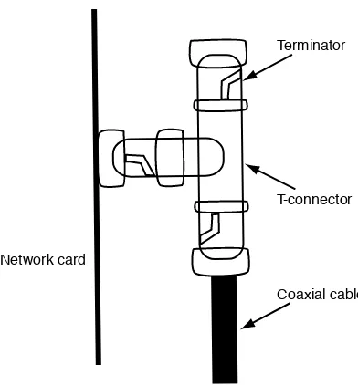
A typical small LAN is shown in Figure 1-1. LANs are wholly owned by an organization and require no licensing or registration. Anyone can purchase the hardware required and
assem-ble a LAN in his or her home or office.
FiGUre 1-1 A typical small LAN.
Devices connected to a LAN, such as computers or printers, are generically referred to as nodes. A 50-node network is therefore a single network medium with 50 computers or other devices connected to it.
Key
exAm tip
Virtually all of the wired LANs installed today use a technology known as Ethernet or, more precisely, IEEE 802.3. There are several other antiquated LAN technologies, including Token ring and FDDI, that are no longer covered by the Network+ exam, and for which products are no longer available on the market, but that you might conceivably encounter in older installations.
LANs are expandable within certain limits imposed by the protocols they use to commu-nicate, but in large installations, it is often necessary to connect multiple LANs together. To do this, you use a device called a router, as shown in Figure 1-2. A router is simply a device
that connects networks together, forming what is known as a “network of networks” or, more commonly, an “internetwork.”
Router
FiGUre 1-2 Two LANs connected by a router.
Note internet or internet?
Do not confuse the terms “internetwork” or “internet” (with a lowercase “i”) with the
Inter-net (with a capital “I”). The term “InterInter-net” describes a specific example of that for which “internetwork” is the generic designation. In other words, the Internet is a specific type of internetwork, but not every use of the term “internetwork” refers to the Internet.
A wide area network (WAN) is a group of computers connected by a longer distance communication technology provided by a third-party service provider, such as a telephone company. Internet connections for LANs or individual computers, whether they use dial-up
modems and telephone lines or broadband technologies, are all WAN links. Corporate net
-works also use WAN technologies to connect offices at remote sites together. Most WAN con -nections are point-to-point links joining two sites together; a company with multiple branch
offices in different cities might have separate WAN links connecting each branch to the main
Key
Router Router
WAN Link
FiGUre 1-3 Two LANs connected by a WAN link.
moRe iNfo waN techNOLOGies
For more information on the various types of WAN technologies currently in use, see Chapter 10, “Wide Area Networking.”
WAN connections can take many forms and use many different communications technol -ogies. Subscribers, whether private individuals or large companies, can choose from among
a variety of WAN providers offering connections with different speeds and services. Gener
-ally speaking, WAN connections are much slower than LAN connections and are far more expensive. Most LANs today run at 100 or 1,000 megabits per second (Mbps), and the only
costs involved are for the required hardware components. WAN connections typically run at
speeds of up to 4 Mbps for residential Internet connections, and up to 25 Mbps for business connections. Very few even approach the speed of a modest LAN. Subscription prices vary depending on the speed of the connection and the other services provided.
Signals and protocols
All of the computers connected to a network communicate by exchanging signals with each other. The nature of the signals depends on the network medium. The three most common types of signals used for network communications are as follows:
■ electrical Networks that use copper-based cables as a medium communicate by us-ing electrical signals, voltages generated by the transceiver in each node.
■ Light Fiber optic cables carry signals in the form of pulses of light, and some wireless networks use infrared light as a signaling medium.
■ radio Most wireless networks communicate by using radio signals.
specific radio frequency variations. The process by which complex data structures, such as
print jobs, email messages, and video streams, get reduced to simple signals is the responsi-bility of software components called protocols, which run on each computer.
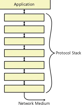
Protocols are essentially languages that operate at various levels of the networking soft-ware on each computer or other device. Just as two people must speak the same language to be able to talk to each other, two computers on the same network must use the same protocols to communicate. Unlike human speech, however, which uses a single language, a networked computer uses multiple protocols in layers, forming a construction known as a protocol stack.
The signals that the computer transmits over the network medium are at the bottom of the stack, and the applications that handle the data are at the top, as shown in Figure 1-4. One of the primary functions of the protocol stack is to reduce the data generated by the applications running on the computer down to the simple signals suitable for the network
medium. When the signals arrive at their destination, the protocol stack performs the same
process in reverse, interpreting the incoming signals and restoring them to their original form.
Application
Network Medium
Protocol Stack
FiGUre 1-4 The protocol stack on a networked computer.
Ethernet, TCP, IP, and SMTP are all protocols operating at various layers of a typical
net-worked computer’s protocol stack. A large part of the Network+ exam is devoted to testing
your knowledge and understanding of these various protocols.
■ addressing A system for assigning a unique designation to each computer on a
network and using those designations to transmit data to specific computers
■ acknowledgment The transmission of a return message by the receiving system to verify the receipt of data
■ segmentation The division of a large block of data into segments sufficiently small for transmission over the network
■ Flowcontrol The generation of messages by a receiving system that instruct the sending system to speed up or slow down its rate of transmission
■ error detection The inclusion of special codes in a data transmission that the receiv-ing system uses to verify that the data was not damaged in transit
■ error correction The retransmission of data that has been corrupted or lost on the way to its destination
■ encryption The encoding of data with a cryptographic key to protect it during trans-mission over the network
■ compression The removal of redundant information from data blocks to minimize the amount of data transmitted over the network
Most of the networking protocols in use today are based on open standards so that differ-ent manufacturers can produce implemdiffer-entations that are fully compatible. Some of the orga-nizations that are responsible for designing the networking protocol standards are as follows:
■ institute of electrical and electronics engineers (ieee) The US-based society re-sponsible for the publication of the IEEE 802.3 working group, which includes the
stan-dards that define the protocol commonly known as Ethernet, as well as many others.
■ international Organization for standardization (isO) A worldwide federation of standards bodies from more than 100 countries, responsible for the publication of the Open Systems Interconnection (OSI) reference model document.
■ internet engineering task Force (ietF) An ad hoc group of contributors and con-sultants that collaborates to develop and publish standards for Internet technologies, including the Transmission Control Protocol/Internet Protocol (TCP/IP) protocols.
■ american National standards institute (aNsi) A private, nonprofit organization that administers and coordinates the United States’ voluntary standardization and
conformity assessment system. ANSI is the official US representative to the ISO, as well
as to several other international bodies.
■ telecommunications industry association/electronic industries alliance (tia/
eia) Two organizations that have joined together to develop and publish the
Com-mercial Building Telecommunications Wiring Standards, which define how the cables
for data networks should be installed.
■ telecommunication standardization sector of the international
packet Switching and Circuit Switching
LANs typically use a shared network medium, meaning that all of the computers are con-nected to a medium that can only carry one signal, and they must take turns using it. A network that can only carry one signal at a time is called a baseband network.
When multiple computers have to share a single baseband network medium, they must
transmit their data in the form of small, discrete units called packets. Otherwise, one computer
might monopolize the network for long periods of time as it transmits large files. Instead of transmitting an entire file all at once, the protocols running on the computer break it down
into packets and transmit them to the destination individually. This way, many computers can gain access to the network and take turns transmitting packets. If you were to imagine the network cable as a hose that has been cut with a knife, you would see packets originating
from many different computers squirt out onto the floor, as shown in Figure 1-5.
Packets Network Medium
FiGUre 1-5 Packets transmitted over a baseband network.
Because computers on a baseband network have to break up their transmissions into
sepa-rate packets, it is conceivable that the packets that compose a single file might take different
routes to their destination, and might even arrive at the destination out of order. The destina-tion system must therefore identify the incoming packets and reassemble them in the proper order to recreate the original data forms transmitted by the sender. This type of arrangement is known as a packet-switching network.
The opposite of a packet-switching network is a circuit-switching network, in which one system opens a circuit (or path) to another system prior to transmitting any data. The circuit then remains open for the duration of the data transaction.
Circuit-switching is not suitable for LANs, because it would monopolize the network medium for long periods. An example of circuit-switching is the Public Switched Telephone
Network (PSTN) through which you receive all of your land-line telephone calls. When you
pick up the ringing phone, it establishes a circuit to the caller’s phone, and that circuit remains
open—even when nobody is talking—until one of you hangs up the receiver.
To make circuit switching practical, some networks use an alternative to baseband com -munications called broadband. In recent years, the term “broadband” has come to refer to any
high-speed Internet connection, but the actual definition of a broadband network is one that
can carry multiple signals on a single network medium. Broadband networks use a technique called multiplexing to divide the bandwidth into separate channels, each of which can carry a Key
Key
Key
Key
One of the most common types of broadband networks is the cable television (CATV) network connection found in many homes. The CATV service enters the home as a single cable, but if you have multiple television sets, each one can be tuned to a different channel. This means that the single cable is carrying the signals for dozens (or hundreds) of different channels simultaneously. That same cable can supply the home with other services as well, including Internet access and video on demand.
Client/Server and peer-to-peer Networks
The basic functions of a network typically involve one computer or other device provid-ing some kind of service to other computers. This relationship is typically referred to as client/server networking. The server side of the partnership can be a computer that provides storage, access to a printer, email services, webpages, or any number of other services. The client is a computer running a program that accesses the services provided by servers.
In the early days of PC networking, these client and server roles were more clearly defined
than they are today. Servers were computers dedicated exclusively to server functions; they could not function as clients.
Today, virtually all of the computers on a network are capable of functioning as both clients and servers simultaneously, and their roles are more a matter of the administrator’s choice than the software running on the computer. This relationship is known as peer-to-peer networking. On a peer-to-peer network, for example, a computer can share its drives with the rest of the network and can also access shared drives on other computers, regardless of whether the system is running a server or a client operating system.
Note cLieNt/server OperatiNG sYstems
One of the few successful network operating system products that operated on a strictly client/server model was Novell NetWare. All Windows, UNIX, and Linux operating systems are capable of using the peer-to-peer model.
Manufacturers of operating systems still tend to market separate server and client versions of their products, but a computer running a server operating system can still function as a client, and many home or small business networks consist solely of computers running client operating systems, which can also function as servers at the same time.
This might seem confusing, but suffice it to say that in today’s computing world, the terms “client” and “server” refer not so much to machines or operating systems as they do to the
roles or applications running on those machines or operating systems. Key
the Osi reference model
As mentioned earlier in this chapter, networked computers use protocols to communicate with each other, and the combination of protocols running at the same time in a network implementation is called the stack. The Open Systems Interconnection (OSI) reference model is a theoretical example of a network protocol stack, which networking students and
adminis-trators use to categorize and define a computer’s various networking functions.
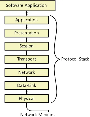
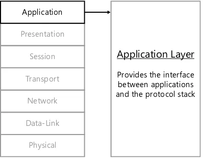
The OSI reference model consists of seven layers, which are as follows, from top to bottom:
■ 7 - Application
■ 6 - Presentation
■ 5 - Session
■ 4 - Transport
■ 3 - Network
■ 2 - Data-link
■ 1 - Physical
Note Osi LaYer NUmbers
The upper layers of the OSI model are seldom referenced by number. The most common use for the layer numbers is in discussions of routing and switching technologies. Switches operate primarily at Layer 2, the data-link layer, and routers at Layer 3, the network layer. however, these devices often have capabilities that span to other layers, resulting in refer-ences to technologies such as Layer 3 switching. For more information, see Chapter 7, “routing and Switching.”
The top of the model interacts with the applications running on the computer, which might at times require the services of the network. The bottom of the model connects to the network medium over which the system transmits its signals, as shown in Figure 1-6. There are different protocols operating at the various layers of the model, each of which provides functions needed to compete the network communication process.
When an application on a computer requests a network service, such as access to a file on
a server or the transmission of an email message, it generates a network access request and
passes it to a protocol operating at the application layer. For example, to access a file on a server, a Windows-based computer uses the Server Message Blocks (SMB) protocol; to send
an email over the Internet, it uses the Simple Mail Transfer Protocol (SMTP).
After processing the request, the application layer protocol then passes the request down
Software Application Application Presentation Session Transport
Network Data-Link
Physical
Network Medium
Protocol Stack
FiGUre 1-6 The seven layers of the OSI reference model.
When the signals arrive at their destination, they start at the bottom of the protocol stack
and work their way up through the layers. The process is exactly the same, but reversed, as shown in Figure 1-7. Eventually, the message arrives at the corresponding application running on the destination computer.
Application Presentation Session Transport
Network Data-Link
Physical
Application Presentation Session Transport
Network Data-Link
Physical
FiGUre 1-7 Protocols provide services to other protocols at adjacent layers, creating a path downward and upward through the stack.
The OSI reference model is defined in a standard document published in 1983 by the
-originally intended to be the model for an actual implementation of a new protocol stack, but this never materialized. Instead, the OSI model has come to be used with the existing network protocols as a teaching and reference tool.
It is important to understand that the actual protocols running in most network imple men-tations do not conform exactly to the architecture of the OSI reference model. For example, the protocol stack in most computers does not consist of precisely seven protocols, with one
operating at each of the seven defined layers. Some of the most commonly used protocols
have functions that span multiple layers, whereas other layers might require two or more
protocols to fulfill their functions.
Despite this lack of an exact correlation between the OSI model and actual networks, how-ever, the IT industry often uses OSI terminology to describe networking functions.
exAm tip
remembering the names of the OSI reference model layers, in the correct order, is an important part of your exam preparation. There are many mnemonics that students use to recall the layer names, ranging from the standard “All people Seem To Need Data process-ing” to the silly “programmers Do Not Throw Sausage pizza Away” to the obscene, which you will have to discover for yourself.
protocol Interaction
The protocols that make up the stack on a particular computer, despite being defined by
different standards bodies and possibly created by different manufacturers, work together to provide all of the networking services required by the computer’s applications and operating system. From a functional perspective, the stack usually is not redundant, meaning that when a protocol at one layer provides a particular service, the protocols at the other layers do not provide the exact same service, even if they are capable of doing so.
Protocols at adjacent layers of the stack provide services for the layer above and request services from the layer below, enabling data to make its way down (or up) through the layers. For example, when there is a choice of protocols at the transport layer, the protocol at the
net-work layer below specifies which of the transport layer protocols the data it is passing upward should use. There is always, therefore, a definitive path that data should take upward or down -ward through the stack, depending on the services needed to transmit or receive the data.
Application Presentation Session Transport
Network Data-Link
Physical
Application Presentation Session Transport
Network Data-Link
Physical
FiGUre 1-8 Protocols operating at the same layer on different computers provide complementary services to each other.
Data Encapsulation
The processing that occurs at each layer of the OSI reference model in most cases involves the application (or removal) of an additional block of data called a header to the protocol data unit (PDU) received from the adjacent layer. This process is called data encapsulation.
The process begins when an application creates a PDU containing a network access request at the application layer, as shown in Figure 1-9.
Application Presentation Session Transport Network Data-Link Physical
Application Request
The application layer protocol then passes the PDU down to the transport layer. The trans-port layer protocol adds a header, creating a PDU of its own with the application layer data as the payload, as shown in Figure 1-10.
Application Presentation Session Transport Network Data-Link Physical
Application Request
Payload Header
FiGUre 1-10 Data encapsulation: the transport layer.
Note tcp/ip LaYers
The TCp protocol stack does not include separate protocols for the presentation and ses-sion layers. These functions are typically integrated into the application layer protocols. however, these two layers do provide a pass-through service that enables protocols at the layers above and below them to exchange data.
The transport layer protocol header consists of fields containing information that imple
-ments the protocol’s various functions. The application layer PDU becomes the data field of
the transport layer PDU.
When the transport layer protocol passes the PDU down to the network layer, the network
layer protocol adds its own header in exactly the same way, as shown in Figure 1-11. Head-ers vary in size, depending on the number and nature of the functions implemented by the protocol.
The process is varied slightly at the data-link layer, which adds both a header and a footer to the network layer PDU, as shown in Figure 1-12.
The following sections examine, in general terms, the functions that occur at each layer of the OSI reference model. For more detailed studies of the various protocols running on today’s computers, see the subsequent chapters in this book, as referenced at the end of each section.
Application Presentation Session Transport Network Data-Link Physical
Application Request
Payload Header
Payload Header
FiGUre 1-11 Data encapsulation: the network layer.
Application Presentation Session Transport Network Data-Link Physical
Application Request
Payload Header
Payload Header
Payload
Header Footer
Quick check
1. Name the layers of the OSI reference model at which protocols apply headers to outgoing packets.
2. On an Ethernet LAN, at which OSI model layer does a protocol apply a footer as well as a header?
Quick check answers
1. Transport, network, and data-link
2. Data-link
The physical Layer
The physical layer, as shown in Figure 1-13, is at the bottom of the OSI reference model.
As the name implies, the physical layer is the layer that defines the hardware elements of
the network, including the following:
■ The network interface found in each computer or other device
■ The nature of the signals used to transmit data over the network
■ The characteristics of the network medium that carries the signals
■ The physical topology of the network
Application
Presentation
Session
Transport
Network
Data-Link
Physical
Physical Layer
Network Medium Network Topology Network Installation
Network Signaling
Physical Layer Specifications for LANs
On a LAN, the physical layer specifications for the network are directly related to the selec -tion of a data-link layer protocol. For example, if you elect to use Ethernet at the data-link
layer, you must choose from among an assortment of physical layer specifications included
in the Ethernet standards. These specifications dictate the types of cable you can use, the maximum lengths of the cables, and the number of devices you can connect to the LAN, among other things.
The data-link layer protocol standards do not necessarily contain all of the physical layer
specifications needed to install a network, however. Some elements are defined in other
standards.
One of the most commonly used physical layer specifications is the “Commercial Building
Telecommunications Cabling Standard,” published jointly by ANSI and the TIA/EIA as docu
-ment 568-C. This docu-ment includes detailed specifications for installing cables for data net -works in a commercial environment, including the required distances for cables from sources of electromagnetic interference and the pinouts for the cable connectors.
In most cases, organizations outsource large LAN cabling jobs to specialized cabling
con-tractors, often the same ones responsible for wiring phone systems and other office infra -structure services. Any contractor you consider for a LAN cabling job should be very familiar with TIA/EIA 568-C and other such documents, including your local building codes.
Physical Layer Specifications for WANs
The physical and data-link specifications for LANs are closely associated because the LAN protocol is largely devoted to the sharing of the network medium among many computers.
WAN links, however, are usually point-to-point connections between two—and only two— systems. As a result, WAN technologies typically use a relatively simple protocol at the
data-link layer called the Point-to-Point Protocol (PPP), which does not contain any physical layer
specifications. The WAN protocol can therefore have a completely independent hardware
implementation at the physical layer.
physical Layer Signaling
The final element found at the physical layer is the signaling method that systems use to transmit data over the network medium. The basic nature of the signals is, of course,
de-termined by the network medium. Copper cables use electrical voltages, fiber optic cables
By the time data reaches the bottom of the protocol stack, it is a simple binary sequence— zeros and ones—and the signaling method is just a mechanism for encoding those binary
digits. The actual signaling scheme that a network uses is not controllable by the network
administrator; it is specified by the data-link layer protocol in the case of a LAN, or by the WAN technology. Therefore, although it might be interesting for a network administrator to
know that Ethernet networks use a signaling scheme called Differential Manchester and how it works, it is not a subject that comes up in daily practice.
moRe iNfo LearNiNG mOre abOUt phYsicaL LaYer prOtOcOLs
For more detailed information about the physical layer specifications of specific types of networks, see the chapters listed in Table 1-1.
tabLe 1-1 Physical Layer Protocol Cross-References
physical Layer protocols chapter coverage
EIA/TIA 568B Chapter 2, “The Physical Layer” IEEE 802.11a/b/g/n Chapter 5, “Wireless Networking” 10Base-T / 100Base-TX / 1000Base-T, and others Chapter 4, “The Data-Link Layer” WAN Protocols Chapter 10, “Wide Area Networking”
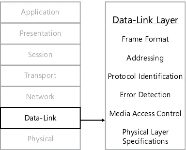
The Data-Link Layer
The data-link layer, as shown in Figure 1-14, is the second layer—or layer 2—of the OSI reference model.
Application
Presentation
Session
Transport
Network
Data-Link
Physical
Data-Link Layer
Frame Format Addressing Protocol Identification
Error Detection Media Access Control
Physical Layer Specifications
The protocol you elect to use at this layer is the primary factor that determines what networking hardware you purchase and how you install it. To implement a data-link layer protocol, you need the following hardware and software:
■ Network interface adapter The hardware device that provides the computer with the actual connection to the network and implements some of the data-link layer pro-tocol functions. Network adapters can be integrated into the computer’s motherboard or take the form of internal expansion cards or external USB devices.
■ Network adapter driver A software device driver that enables the computer to utilize the functions of the network interface adapter hardware.
■ Network cables (or other media) and other connecting hardware ■ Network switches, hubs, or access points
Note NetwOrkiNG withOUt a hUb
Although it is possible to connect computers together without a switch, hub, or access point—by using a crossover cable or an ad hoc wireless network—these are in most cases temporary solutions not suitable for a permanent installation.
Most of these components are designed specifically for a certain data-link layer protocol, and more specifically, for a protocol running at a certain speed. For example, you might de -cide to use Ethernet at the data-link layer, but when purchasing hardware, you must be care-ful to distinguish between products supporting regular Ethernet, Fast Ethernet, and Gigabit Ethernet. Most of the newer products on the market are backward compatible with older, slower devices, but each branch of your network will only be as fast as its slowest link.
It is the network interface adapter in each computer, in combination with the network adapter driver, that actually implements the data-link layer protocol. Some of the data-link layer protocol functions are performed by the adapter independently, before incoming data is passed to the computer and before outgoing data leaves it. Other functions are performed by the driver after the adapter passes incoming data to the computer and before the
com-puter passes outgoing data to the adapter. Generally speaking, end—and higher-priced—adapters contain processors that perform more of the networking functions on
board, rather than leaving them to the system processor.
Data-Link Layer Standards for LANs
In the case of LANs, the data-link layer protocols in most common use today are Ethernet
(IEEE 802.3) and Wi-Fi (IEEE 802.11). The standards for these protocols consist of the following
elements:
■ A frame format
FrAME FOrMAT
Data-link layer LAN protocols use the term frame to refer to the protocol data unit they cre-ate by using the information they receive from the network layer. This is largely because the data-link layer protocol adds both a header and a footer to the network layer PDU.
The data-link layer frame typically performs the following functions:
■ addressing The header and footer that the data-link layer protocol applies functions
as the outermost envelope in the figurative mailing of a packet. The header contains addresses identifying the packet’s sending and receiving systems. These addresses— known as “hardware addresses” or “media access control (MAC) addresses”—are 6-byte
hexadecimal strings hard-coded into the computers’ network interface adapters.
impoRtANt prOtOcOL Data UNits
The protocols operating at the different layers of the OSI reference model use different terms to refer to the pDUs they create. The terms most often found in the networking literature are listed in Table 1-2.
tabLe 1-2 PDU Terminology
Osi model Layer protocol pDU terminology
Data-Link Ethernet Frame
Network Internet Protocol Datagram
Transport User Datagram Protocol Datagram Transport Transmission Control Protocol Segment
Application Various Message
The term “packet” is generic and can refer to the pDU at any stage of the data encapsulation process.
Note Data-LiNk LaYer cOmmUNicatiONs
It is important to understand that data-link layer protocols are limited to communica-tion with systems on the same subnet. A computer might transmit a packet to a destina-tion on another LAN, but the data-link layer protocol is only involved in local subnet communications. The hardware address in a data-link layer protocol header always refers to a system on the same subnet. This typically means that the data-link layer protocol carries the packet only as far as the nearest router. Inside the router, a network
■ Network layer protocol identification The data-link layer protocol header contains
a code that specifies which network layer protocol is encapsulated within the frame.
This way, when the packet works its way up the protocol stack on the receiving system, the data-link layer protocol can determine where to pass the encapsulated data.
■ error detection The transmitting system performs a cyclical redundancy check (CRC) calculation on the data in the frame and appends the result to the packet as a footer.
When the packet arrives at the destination, the receiving system performs the same
calculation. If the results do not match, the receiving system assumes that a transmis-sion error has occurred and discards the packet.
MEDIA ACCESS CONTrOL
When computers are connected to a shared baseband medium, as on a typical LAN, it is pos-sible for two systems to transmit packets at exactly the same time. This results in a collision, causing the corruption and loss of both packets. One of the primary functions of a data-link layer protocol on a LAN is to prevent, minimize, or handle collisions. To do this, the protocol includes a media access control (MAC) mechanism. The MAC mechanism provides each of the computers on the LAN with regular opportunities to transmit its data.
On modern switched Ethernet networks, the switches provide each pair of devices with a dedicated channel, eliminating the need for computers to share the network medium, and consequently reducing the need for a MAC mechanism. Media access control is also not so
elaborate a function on WANs because there are only two systems involved, and they can
simply take turns transmitting.
phYSICAL LAYEr SpECIFICATIONS
One of the main reasons why LAN data-link layer protocol standards include physical layer
specifications is to support the protocol’s MAC mechanism. If, for example, the cables are too long on an Ethernet network, the systems will be unable to detect packet collisions when they occur, and collision detection is one of the critical elements of the Ethernet MAC mechanism. Excessively long cables can also result in signal degradation and the increased likelihood of signal interference.
moRe iNfo LearNiNG mOre abOUt Data-LiNk LaYer prOtOcOLs
For more detailed information about the data-link layer specifications of specific types of
networks, see the chapters listed in Table 1-3.
tabLe 1-3 Data-Link Layer Protocol Cross-References
Data-Link Layer protocols chapter coverage
Ethernet Chapter 4, “The Data-Link Layer”
IEEE 802.11 Chapter 5, “Wireless Networking”
Key