Slides for Chapter 3:
Networking and Internetworking
From
Coulouris, Dollimore and
Kindberg
Distributed Systems:
Concepts and Design
Instructor’s Guide for Coulouris, Dollimore and Kindberg Distributed Systems: Concepts and Design Edn. 4
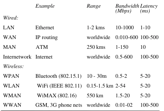
Figure 3.1
Network performance
Example
Range
Bandwidth
(Mbps)
Latency
(ms)
Wired:
LAN
Ethernet
1-2 kms
10-1000 1-10
WAN
IP routing
worldwide 0.010-600 100-500
MAN
ATM
250 kms
1-150
10
Internetwork Internet
worldwide 0.5-600
100-500
Wireless:
WPAN
Bluetooth (802.15.1) 10 - 30m
0.5-2
5-20
WLAN
WiFi (IEEE 802.11) 0.15-1.5 km 2-54
5-20
WMAN
WiMAX (802.16)
550 km
1.5-20
5-20
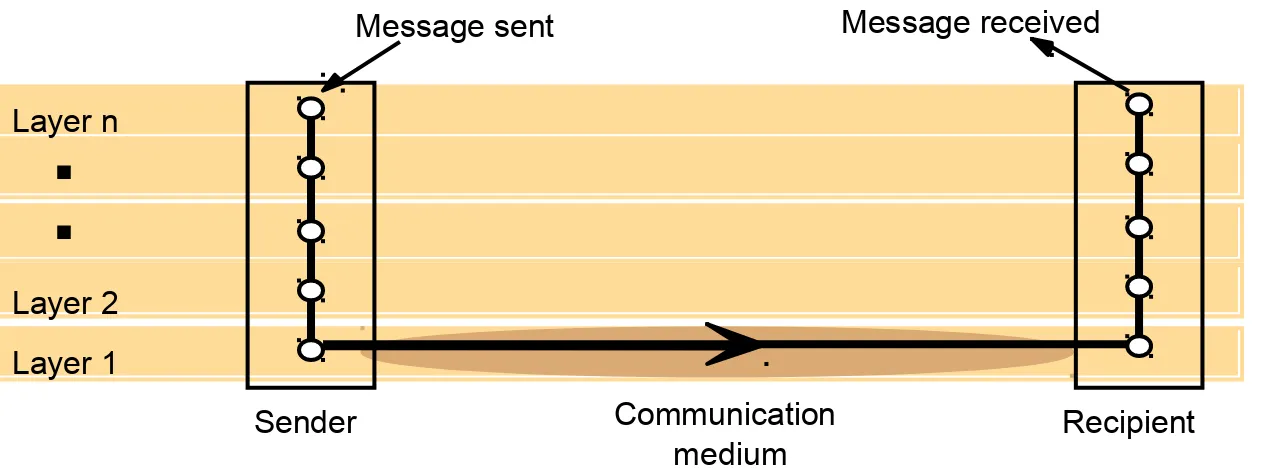
Figure 3.2
Conceptual layering of protocol software
Layer n
Layer 2
Layer 1
Message sent
Message received
Communication
medium
Instructor’s Guide for Coulouris, Dollimore and Kindberg Distributed Systems: Concepts and Design Edn. 4
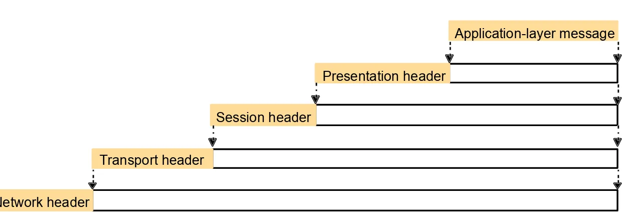
Figure 3.3
Encapsulation as it is applied in layered protocols
Presentation header
Application-layer message
Session header
Transport header
Figure 3.4
Protocol layers in the ISO Open Systems Interconnection (OSI) model
Application
Presentation
Session
Transport
Network
Data link
Physical
Message sent
Message received
Sender
Recipient
Layers
Instructor’s Guide for Coulouris, Dollimore and Kindberg Distributed Systems: Concepts and Design Edn. 4
Figure 3.5
OSI protocol summary
Layer
Description
Examples
Application
Protocols that are designed to meet the communication requirements of
specifc applications, often defning the interface to a service.
HTTP,
CORBA IIOP
FTP
, SMTP,
Presentation
Protocols at this level transmit data in a network representation that is
independent of the representations used in individual computers, which may
difer. Encryption is also performed in this layer, if required.
Secure Sockets
(SSL),CORBA Data
Rep.
Session
At this level reliability and adaptation are performed, such as detection of
failures and automatic recovery.
Transport
This is the lowest level at which messages (rather than packets) are handled.
Messages are addressed to communication ports attached to processes,
Protocols in this layer may be connection-oriented or connectionless.
TCP, UDP
Network
Transfers data packets between computers in a specifc network. In a WAN
or an internetwork this involves the generation of a route passing through
routers. In a single LAN no routing is required.
IP, ATM virtual
circuits
Data link
Responsible for transmission of packets between nodes that are directly
connected by a physical link. In a WAN transmission is between pairs of
routers or between routers and hosts. In a LAN it is between any pair of hosts.
Ethernet MAC,
ATM cell transfer,
PPP
Physical
The circuits and hardware that drive the network. It transmits sequences of
binary data by analogue signalling, using amplitude or frequency modulation
of electrical signals (on cable circuits), light signals (on fbre optic circuits)
or other electromagnetic signals (on radio and microwave circuits).
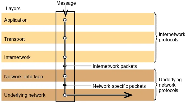
Figure 3.6
Internetwork layers
Underlying network
Application
Network interface
Transport
Internetwork
Internetwork packets
Network-specific packets
Message
Layers
Internetwork
protocols
Instructor’s Guide for Coulouris, Dollimore and Kindberg Distributed Systems: Concepts and Design Edn. 4
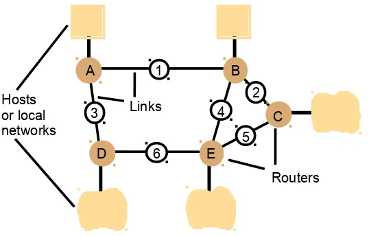
Figure 3.7
Routing in a wide area network
Hosts
Links
or local
networks
A
D
E
B
C
1
2
5
4
3
6
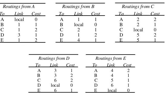
Figure 3.8
Routing tables for the network in Figure 3.7
Routings from D
Routings from E
To
Link
Cost
To
Link
Cost
A
Routings from A
Routings from B
Routings from C
To
Link
Cost
To
Link
Cost
To
Link
Cost
Instructor’s Guide for Coulouris, Dollimore and Kindberg Distributed Systems: Concepts and Design Edn. 4
Figure 3.9
Pseudo-code for RIP routing algorithm
Send:
Each
t
seconds or when
Tl
changes, send
Tl
on each non-faulty
outgoing link.
Receive:
Whenever a routing table
Tr
is received on link
n
:
for all rows
Rr
in
Tr
{
if (
Rr.link
|
n
) {
Rr.cost
=
Rr.cost
+ 1;
Rr.link
=
n
;
if (
Rr.destination
is not in
Tl
) add
Rr
to
Tl;
// add new destination to
Tl
else for all rows
Rl
in
Tl
{
if (
Rr.destination
=
Rl.destination
and
(Rr.cost
<
Rl.cost
or
Rl.link
=
n
))
Rl
=
Rr;
//
Rr.cost < Rl.cost : remote node has better route
//
Rl.link = n
: remote node is more authoritative
}
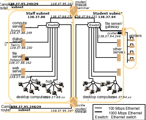
Figure 3.10
Simplified view of the QMW Computer Science network (in mid-2000)
file
desktop computers
138.37.88.xx
subnet
desktop computers
Eswitch
138.37.94
hub
hub
Student subnet
Staf subnet
other
1000 Mbps Ethernet
Eswitch: Ethernet switch
100 Mbps Ethernet
file server/
Instructor’s Guide for Coulouris, Dollimore and Kindberg Distributed Systems: Concepts and Design Edn. 4
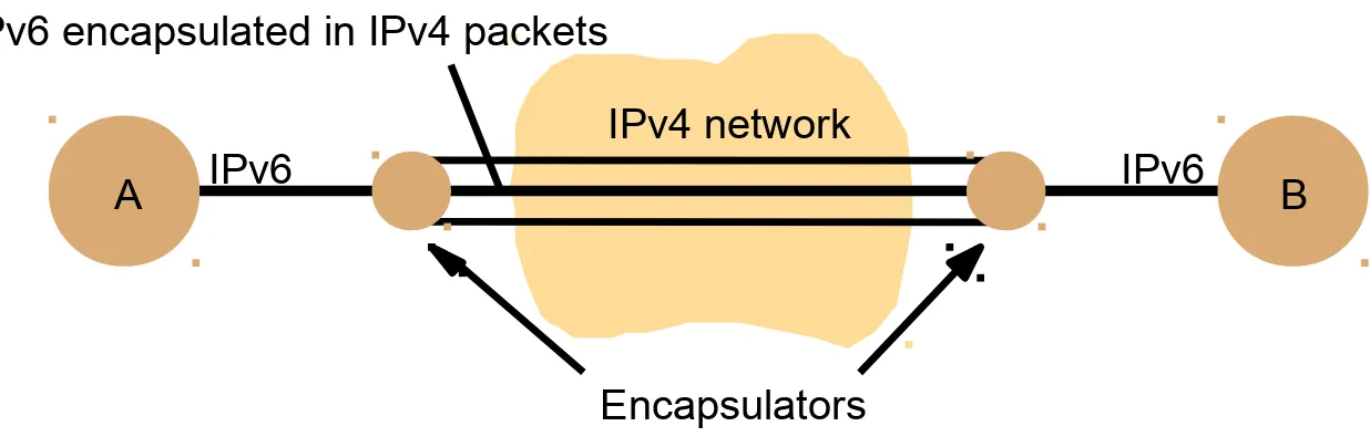
Figure 3.11
Tunnelling for IPv6 migration
A
IPv6
IPv6
B
IPv6 encapsulated in IPv4 packets
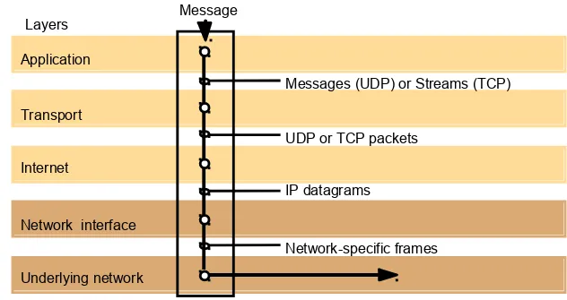
Figure 3.12
TCP/IP layers
Messages (UDP) or Streams (TCP)
Application
Transport
Internet
UDP or TCP packets
IP datagrams
Network-specific frames
Message
Layers
Instructor’s Guide for Coulouris, Dollimore and Kindberg Distributed Systems: Concepts and Design Edn. 4
Figure 3.13
Encapsulation in a message transmitted via TCP over an Ethernet
Application message
TCP header
IP header
Ethernet header
Ethernet frame
port
TCP
Figure 3.14
The programmer's conceptual view of a TCP/IP Internet
IP
Application
Application
Instructor’s Guide for Coulouris, Dollimore and Kindberg Distributed Systems: Concepts and Design Edn. 4
Figure 3.15
Internet address structure, showing field sizes in bits
7
24
Class A:
0
Network ID
Host ID
14
16
Class B:
1 0
Network ID
Host ID
21
8
Class C:
1 1 0
Network ID
Host ID
28
Class D (multicast):
1 1 1 0
Multicast address
Figure 3.16
Decimal representation of Internet addresses
octet 1
octet 2
octet 3
Class A:
1 to 127
0 to 255
0 to 255
1 to 254
Class B:
128 to 191
Class C:
192 to 223
224 to 239
Class D (multicast):
Network ID
Network ID
Network ID
Host ID
Host ID
Host ID
Multicast address
0 to 255
0 to 255
1 to 254
0 to 255
0 to 255
0 to 255
0 to 255
0 to 255
0 to 255
Multicast address
0 to 255
0 to 255
1 to 254
240 to 255
Class E (reserved):
Instructor’s Guide for Coulouris, Dollimore and Kindberg Distributed Systems: Concepts and Design Edn. 4
Figure 3.17
IP packet layout
data
IP address of destination
IP address of source
header
Figure 3.18
A typical NAT-based home network
83.215.152.95
Ethernet switch
Modem / firewall / router (NAT enabled)
printer
DSL or Cable
connection to ISP
192.168.1.xx
subnet
PC 1
WiFi base station/
access point
192.168.1.10
192.168.1.5
192.168.1.2
192.168.1.1
192.168.1.104
PC 2
192.168.1.101
Laptop
192.168.1.105
Game box
192.168.1.106
Media hub
TV monitor
Bluetooth
adapter
Bluetooth
printer
Instructor’s Guide for Coulouris, Dollimore and Kindberg Distributed Systems: Concepts and Design Edn. 4
Figure 3.19
IPv6 header layout
Source address
(128 bits)
Destination address
(128 bits)
Version (4 bits)
Trafc class (8 bits)
Flow label (20 bits)
Figure 3.20
The MobileIP routing mechanism
Sender
Home
Mobile host MH
Foreign agent FA
Internet
agent
First IP packet
addressed to MH
Address of FA
returned to sender
Instructor’s Guide for Coulouris, Dollimore and Kindberg Distributed Systems: Concepts and Design Edn. 4
Figure 3.21
Firewall configurations
Internet
Router/
Protected intranet
a) Filtering router
Internet
b) Filtering router and bastion
filter
Internet
R/filter
c) Screened subnet for bastion
R/filter
Bastion
R/filter
Bastion
web/ftp
server
web/ftp
server
web/ftp
Figure 3.22
IEEE 802 network standards
IEEE No. Name
Title
Reference
802.3
Ethernet CSMA/CD Networks (Ethernet)
[IEEE 1985a]
802.4
Token Bus Networks
[IEEE 1985b]
802.5
Token Ring Networks
[IEEE 1985c]
802.6
Metropolitan Area Networks
[IEEE 1994]
Instructor’s Guide for Coulouris, Dollimore and Kindberg Distributed Systems: Concepts and Design Edn. 4
Figure 3.23
Ethernet ranges and speeds
10Base5
10BaseT
100BaseT
1000BaseT
Data rate
10 Mbps
10 Mbps
100 Mbps
1000 Mbps
Max. segment lengths:
Twisted wire (UTP) 100 m
100 m
100 m
25 m
Figure 3.24
Wireless LAN configuration
LAN
Server
Wireless
LAN
Laptops
Base station/
access point
Palmtop
radio obstruction
A
B
C
D
Instructor’s Guide for Coulouris, Dollimore and Kindberg Distributed Systems: Concepts and Design Edn. 4
Figure 3.25
Bluetooth frame structure
SCO packets (e.g. for voice data) have a 240-bit payload
containing 80 bits of data triplicated, flling exactly one timeslot.
bits: 72
18
18
18
0 - 2744
Access code
Header
copy 1
Header
copy 2
Header
copy 3
Data for transmission
bits: 3
1
1
1
4
8
Destination
Flow Ack
Seq
Type
Header checksum
Address within
Piconet
= ACL, SCO,
poll, null
Figure 3.26
ATM protocol layers
Physical
Application
ATM layer
Higher-layer protocols
ATM cells
ATM virtual channels
Message
Layers
Instructor’s Guide for Coulouris, Dollimore and Kindberg Distributed Systems: Concepts and Design Edn. 4