1
Wireless LANs
Wireless LANs
EPL 657
EPL 657
Panayiotis Kolios
Panayiotis Kolios
Contains slides and ideas from
Teknillinen Korkeakoulou, Finland: Wireless personal, local, metropolitan, and wide area networks, S-72.3240, and
WIRELESS LAN (WLAN)
WIRELESS LAN (WLAN)
Selected topicsSelected topics
» IntroductionIntroduction » WLAN aimsWLAN aims
» WLAN characteristicsWLAN characteristics » WLAN design goalsWLAN design goals
» Infrared vs radio transmissionInfrared vs radio transmission
» Infrastructure-based vs ad-hoc networksInfrastructure-based vs ad-hoc networks » WLAN StandardsWLAN Standards
» IEEE 802.11IEEE 802.11 » WLAN RoamingWLAN Roaming » WLAN SecurityWLAN Security
3
Why Wireless LANs (WLANs)
Why Wireless LANs (WLANs)
Mobility (portability)
Mobility (portability)
and Flexibility
and Flexibility
Places where there is no cabling infrastructure /
Places where there is no cabling infrastructure /
Hard to wire areas
Hard to wire areas
Reduced cost of wireless systems
Reduced cost of wireless systems
Improved flexibility of wireless systems
Improved flexibility of wireless systems
Cost
Cost
–
Relatively low cost of deployment
Relatively low cost of deployment
Wireless LAN Applications
Wireless LAN Applications
LAN Extension
LAN Extension
Cross building interconnection
Cross building interconnection
Nomadic access
Nomadic access
5
Vertical Markets
Vertical Markets
Factory foor
Factory foor
Home
Home
networking
networking
Hospital
Hospital
Ofice workers
Ofice workers
Retail stores
Retail stores
Warehouse
Warehouse
Stock market
Stock market
Airport
Airport
Hotel
Hotel
Starbuck
Starbuck
College
College
campus
campus
Convention
Convention
Center
Center
Example WLAN
Example WLAN
deployment - Hotel
deployment - Hotel
Competing Technologies
Competing Technologies
Wired Ethernet (802.3)
Wired Ethernet (802.3)
Phone Line
Phone Line
xDSL
xDSL
Power Line
Power Line
Proposed: Wireless LAN (802.11)
Proposed: Wireless LAN (802.11)
Why: Price/Performance and ease of
Why: Price/Performance and ease of
deployment
deployment
7
Wireless LANs
Wireless LAN considerations
Wireless LAN considerations
Throughput
Throughput
Number of nodes
Number of nodes
Connection to backbone
Connection to backbone
Service area
Service area
Battery power consumption
Battery power consumption
Transmission robustness and security
Transmission robustness and security
Collocated network operation
Collocated network operation
9
WLANs goal
WLANs goal
A mature market introducing the flexibility of wireless
A mature market introducing the flexibility of wireless
access into office, home, or production environments.
access into office, home, or production environments.
Typically restricted in their diameter to buildings, a
Typically restricted in their diameter to buildings, a
campus, single rooms etc.
campus, single rooms etc.
The global goal of WLANs is to
The global goal of WLANs is to
replace office cabling,
replace office cabling,
increase flexibility of connection especially for portable
increase flexibility of connection especially for portable
devices and, additionally, to introduce a higher flexibility
devices and, additionally, to introduce a higher flexibility
for ad hoc communication in, e.g., group meetings
for ad hoc communication in, e.g., group meetings
.
.
WLAN characteristics
WLAN characteristics
Advantages:
Advantages:
–
very
very
flexible
flexible
within radio coverage
within radio coverage
–
ad-hoc networks
ad-hoc networks
without
without
previous
previous
planning
planning
possible
possible
–
wireless networks allow for the
wireless networks allow for the
design
design
of small,
of small,
independent devices
independent devices
11
WLAN characteristics
WLAN characteristics
Disadvantages:
Disadvantages:
–
typically
typically
lower bandwidth
lower bandwidth
compared to wired networks (~11
compared to wired networks (~11
– 300 Mbit/s) due to limitations in radio transmission,
– 300 Mbit/s) due to limitations in radio transmission,
higher
higher
error rates
error rates
due to interference, and
due to interference, and
higher delay/delay
higher delay/delay
variation
variation
due to extensive error correction and error detection
due to extensive error correction and error detection
mechanisms
mechanisms
» offer lower QoSoffer lower QoS
–
a number of
a number of
proprietary solutions
proprietary solutions
, especially for higher bit-
, especially for higher
bit-rates, standards take their time (e.g., IEEE 802.11n)
rates, standards take their time (e.g., IEEE 802.11n)
» standardized functionality plus many enhanced featuresstandardized functionality plus many enhanced features
» additional features only work in a homogeneous environment (i.e., additional features only work in a homogeneous environment (i.e.,
when adapters from same vendors used)
when adapters from same vendors used)
WLAN design goals
WLAN design goals
global
global
,
,
seamless operation
seamless operation
of WLAN products
of WLAN products
low power
low power
for battery use (special power saving modes and
for battery use (special power saving modes and
power management functions)
power management functions)
no special permissions or licenses needed (
no special permissions or licenses needed (
license-free
license-free
band)
band)
robust
robust
transmission technology
transmission technology
easy
easy
to use for everyone, simple management
to use for everyone, simple management
protection of investment
protection of investment
in wired networks (support the same
in wired networks (support the same
data types and services)
data types and services)
security
security
– no one should be able to read other’s data,
– no one should be able to read other’s data,
privacy
privacy
–
–
no one should be able to collect user profiles,
no one should be able to collect user profiles,
safety
safety
– low
– low
radiation
13
Known problems with WLANs
Wireless link characteristics: media is error prone and the
bit error rate (
BER
) is very
high
compared to the BER of
wired networks.
Carrier Sensing/collision detection
is
difficult
in
wireless networks because a station is incapable of
listening to its own transmissions in order to detect a
collision
(more later).
The
Hidden Terminal
problem
also decreases the
performance of a WLAN
(more later).
Wireless Link Characteristics
Wireless Link Characteristics
Differences from wired link ….
Differences from wired link ….
–
decreased signal strength:
decreased signal strength:
radio signal attenuates as
radio signal attenuates as
it propagates through matter (path loss)
it propagates through matter (path loss)
–
interference from other sources:
interference from other sources:
standardized
standardized
wireless network frequencies (e.g., 2.4 GHz) shared
wireless network frequencies (e.g., 2.4 GHz) shared
by other devices (e.g., phone); also devices (e.g.
by other devices (e.g., phone); also devices (e.g.
motors) interfere as well (
motors) interfere as well (
noise
noise
)
)
–
multipath propagation:
multipath propagation:
radio signal reflects off
radio signal reflects off
objects, arriving at destination at slightly different
objects, arriving at destination at slightly different
times (
times (
channel quality varies over time
channel quality varies over time
)
)
15
Wireless LAN Radio Technology
Wireless LAN Radio Technology
Infrared (IR) LANs
Infrared (IR) LANs
Spread spectrum LANs
Spread spectrum LANs
Narrow band microwave
Narrow band microwave
ISM frequency bands
ISM frequency bands
ISM (Industrial, Scientific and Medical) frequency bands:
• 900 MHz band (902 … 928 MHz)
•
2.4 GHz band (2.4 … 2.4835 GHz)
• 5.8 GHz band (5.725 … 5.850 GHz)
Anyone is allowed to use radio equipment for transmitting in these bands (provided specific
17
Several WLAN standards:
Several WLAN standards:
–
IEEE 802.11b
IEEE 802.11b
offering 11 Mbit/s at 2.4 GHz
offering 11 Mbit/s at 2.4 GHz
–
The same radio spectrum is used by
The same radio spectrum is used by
Bluetooth
Bluetooth
»
A short-range technology to set-up wireless personal area
A short-range technology to set-up wireless personal area
networks with gross data rates less than 1 Mbit/s
networks with gross data rates less than 1 Mbit/s
–
IEEE
IEEE
802.11a
802.11a
, operating at 5 GHz and offering gross
, operating at 5 GHz and offering gross
data rates of 54 Mbit/s
data rates of 54 Mbit/s
–
IEEE
IEEE
802.11g
802.11g
offering up to 54 Mbit/s at 2.4 GHz.
offering up to 54 Mbit/s at 2.4 GHz.
–
IEEE
IEEE
802.11n
802.11n
up and coming standard up to 300 Mbit/s
up and coming standard up to 300 Mbit/s
(two spatial streams; 600 Mbit/s with 4 spatial streams)
(two spatial streams; 600 Mbit/s with 4 spatial streams)
WLAN Standards
19
IEEE 802 standardisation framework
802.1 802.2 Logical Link Control (LLC)
802.11 Medium Access Control (MAC)
CSMA/CD (Ethernet)
CSMA/CA
Token
Ring CSMA/CA (Wireless LAN) 802.11n
IEEE 802 wireless network technology options
Network definition
Wireless personal area network (WPAN)
Low-rate WPAN (LR-WPAN)
Wireless local area network (WLAN)
Wireless metroplitan
IEEE standard
IEEE 802.15.1
IEEE 802.15.4
IEEE 802.11
IEEE 802.16
Known as
Bluetooth
ZigBee
WiFi
21
IEEE 802.11 standard
IEEE 802.11 standard
As the
As the
standards
standards
number indicates, this standard belongs
number indicates, this standard belongs
to the group of
to the group of
802.x
802.x
LAN standards
LAN standards
.
.
This means that the standard specifies the
This means that the standard specifies the
physical and
physical and
medium access layer
medium access layer
adapted to the special requirements
adapted to the special requirements
of wireless LANs, but
of wireless LANs, but
offers
offers
the
the
same interface as the
same interface as the
others to higher layers
others to higher layers
to maintain interoperability.
to maintain interoperability.
The primary goal of the standard was the specification of a
The primary goal of the standard was the specification of a
simple and robust WLAN
simple and robust WLAN
which offers time-bounded and
which offers time-bounded and
asynchronous services.
IEEE 802.11 Wireless LAN
IEEE 802.11 Wireless LAN
802.11b802.11b
– 2.4-5 GHz unlicensed spectrum2.4-5 GHz unlicensed spectrum – up to 11 Mbpsup to 11 Mbps
– direct sequence spread spectrum (DSSS) in direct sequence spread spectrum (DSSS) in
physical layer
physical layer
» all hosts use same chipping codeall hosts use same chipping code
802.11a802.11a
– 5-6 GHz range5-6 GHz range – up to 54 Mbpsup to 54 Mbps
» Shading is much more severe compared to Shading is much more severe compared to
2.4 GHz
2.4 GHz
» Depending on the SNR, propagation Depending on the SNR, propagation
conditions and distance between sender
conditions and distance between sender
and receiver, data rates may drop fast
and receiver, data rates may drop fast
802.11g802.11g
– 2.4-5 GHz range2.4-5 GHz range – up to 54 Mbpsup to 54 Mbps
– Benefits from the better Benefits from the better
propagation characteristics at 2.4
propagation characteristics at 2.4
GHz compared to 5 GHz
GHz compared to 5 GHz
» Backward compatible to 802.11bBackward compatible to 802.11b
802.11n: 802.11n: multiple antennaemultiple antennae
– 2.4-5 GHz range2.4-5 GHz range – typically 200 Mbpstypically 200 Mbps
IEEE 802.11eIEEE 802.11e
– MAC enhancements for MAC enhancements for
providing some QoS
providing some QoS
» Some QoS guarantees can be given Some QoS guarantees can be given only via polling using PCF
23
Characteristics of selected wireless
Characteristics of selected wireless
link standards
link standards
Indoor
IS-95, CDMA, GSM 2G
UMTS/WCDMA, CDMA2000 3G
802.15 802.11b 802.11a,g
UMTS/WCDMA-HSPDA, CDMA2000-1xEVDO 3G cellular
Infrastructure-based vs ad-hoc
Infrastructure-based vs ad-hoc
wireless networks
wireless networks
Infrastructure networks provide access to other networks.
Infrastructure networks provide access to other networks.
Communication typically takes place only between the
Communication typically takes place only between the
wireless nodes and the access point, but not directly
wireless nodes and the access point, but not directly
between the wireless nodes.
between the wireless nodes.
AP AP
AP
wired network
AP: Access Point
25
Infrastructure-based vs ad-hoc
Infrastructure-based vs ad-hoc
wireless networks
wireless networks
Several wireless networks may form one logical wireless network:
Several wireless networks may form one logical wireless network:
– The access points together with the fixed network in between can connect The access points together with the fixed network in between can connect several wireless networks to form a larger network beyond actual radio several wireless networks to form a larger network beyond actual radio coverage.
coverage.
Network functionality lies within the access point (controls network
Network functionality lies within the access point (controls network
flow), whereas the wireless clients can remain quite simple.
flow), whereas the wireless clients can remain quite simple.
Can use different access schemes with or without collision.
Can use different access schemes with or without collision.
– Collisions may occur if medium access of the wireless nodes and the access Collisions may occur if medium access of the wireless nodes and the access point is not coordinated.
point is not coordinated.
» If only the access point controls medium access, no collisions are possible.If only the access point controls medium access, no collisions are possible.
Infrastructure-based vs ad-hoc
Infrastructure-based vs ad-hoc
wireless networks
wireless networks
Infrastructure-based wireless networks lose some of the
Infrastructure-based wireless networks lose some of the
flexibility wireless networks can offer in general:
flexibility wireless networks can offer in general:
–
They cannot be used for disaster relief in cases where no
They cannot be used for disaster relief in cases where no
infrastructure is left.
27
Infrastructure-based vs ad-hoc
Infrastructure-based vs ad-hoc
wireless networks
wireless networks
No need of any infrastructure to work
No need of any infrastructure to work
–
greatest possible flexibility
greatest possible flexibility
Each node communicate with other nodes, so no access
Each node communicate with other nodes, so no access
point controlling medium access is necessary.
point controlling medium access is necessary.
–
The complexity of each node is much higher
The complexity of each node is much higher
» implement medium access mechanisms and forwarding dataimplement medium access mechanisms and forwarding data
Infrastructure-based vs ad-hoc
Infrastructure-based vs ad-hoc
wireless networks
wireless networks
Nodes within an ad-hoc network can only communicate if
Nodes within an ad-hoc network can only communicate if
they can reach each other physically
they can reach each other physically
–
if they are within each other’s radio range
if they are within each other’s radio range
–
if other nodes can/want to forward the message
if other nodes can/want to forward the message
IEEE 802.11 WLANs are typically infrastructure-based
IEEE 802.11 WLANs are typically infrastructure-based
networks, which additionally support ad-hoc networking
networks, which additionally support ad-hoc networking
29
Elements of a wireless network
Elements of a wireless network
network infrastructure
wireless hosts
wireless hosts
laptop, PDA, IP phonelaptop, PDA, IP phone run applicationsrun applications
may be stationary (non-may be stationary
(non-mobile) or mobile mobile) or mobile
– wireless does wireless does notnot always always mean mobility
Elements of a wireless network
Elements of a wireless network
network infrastructure
base stationbase station
typically connected to typically connected to
wired network wired network
relay - responsible for relay - responsible for
sending packets between sending packets between
wired network and wired network and
wireless host(s) in its wireless host(s) in its
“area” “area”
31
Elements of a wireless network
Elements of a wireless network
network infrastructure
wireless linkwireless link
typically used to connect typically used to connect
mobile(s) to base station mobile(s) to base station
also can be used as also can be used as
backbone links backbone links
multiple access protocol multiple access protocol
coordinates link access coordinates link access
various data rates, various data rates,
Elements of a wireless network
Elements of a wireless network
network infrastructure
infrastructure mode
infrastructure mode
base station connects base station connects
mobiles into wired mobiles into wired network
network
handoff: mobile changes handoff: mobile changes
33
Elements of a wireless network
Elements of a wireless network
Ad hoc mode
Ad hoc mode
no base stationsno base stations
nodes can only transmit nodes can only transmit
to other nodes within link to other nodes within link coverage
coverage
nodes organize nodes organize
themselves into a themselves into a
network: route among network: route among themselves
themselves
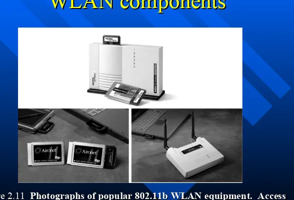
WLAN components
35
IEEE 802.11 terminology
IEEE 802.11 terminology
Basic Service Set (Basic Service Set (BSSBSS))
– group of stations using the same group of stations using the same
radio frequency
radio frequency
Access Point (Access Point (APAP))
– station integrated into the wireless station integrated into the wireless
LAN and the distribution system
LAN and the distribution system
Station (STAStation (STA))
– terminal with access mechanisms to terminal with access mechanisms to
the wireless medium and radio
the wireless medium and radio
contact to the access point
contact to the access point
PortalPortal
– bridge to other (wired) networksbridge to other (wired) networks
Distribution System (Distribution System (DSDS))
– interconnection network to form one interconnection network to form one
logical network
logical network
Extended Service Set (Extended Service Set (EESEES))
– based on several BSSbased on several BSS
Distribution System
System Architecture
IEEE 802.11 BSS
IEEE 802.11 BSS
IEEE 802.11 allows the building of ad hoc
IEEE 802.11 allows the building of ad hoc
networks between stations, thus forming one or
networks between stations, thus forming one or
more BSSs.
more BSSs.
–
In this case, a BSS comprises a group of stations using
In this case, a BSS comprises a group of stations using
the same radio frequency.
the same radio frequency.
–
Several BSSs can either be formed via the distance
Several BSSs can either be formed via the distance
between the BSSs or by using different carrier
Distribution System (DS)
Distribution System (DS)
Used to interconnect wireless cells
Used to interconnect wireless cells
(multiple BSS to form an ESS)
(multiple BSS to form an ESS)
Allows multiple mobile stations to access
Allows multiple mobile stations to access
fixed resources
fixed resources
Interconnects 802.11 technology
Interconnects 802.11 technology
Access Points (AP)
Access Points (AP)
Allows stations to associate with it
Allows stations to associate with it
Supports Point Coordination Function (PCF)
Supports Point Coordination Function (PCF)
Provides management features
Provides management features
–
Join/Associate with BSS
Join/Associate with BSS
–
Time synchronisation (beaconing)
Time synchronisation (beaconing)
–
Power management
Power management
39
IEEE standard 802.11
IEEE standard 802.11
IEEE 802.11 protocol
IEEE 802.11 protocol
Protocol architecture aims
Protocol architecture aims
–
Applications should not notice any difference apart
Applications should not notice any difference apart
from the lower bandwidth and perhaps higher access
from the lower bandwidth and perhaps higher access
time from the wireless LAN.
time from the wireless LAN.
»
WLAN behaves like, perhaps a ‘slower’, wired LAN.
WLAN behaves like, perhaps a ‘slower’, wired LAN.
–
Consequently, the higher layers (application, TCP, IP)
Consequently, the higher layers (application, TCP, IP)
look the same for the wireless node as for the wired
look the same for the wireless node as for the wired
node.
41
IEEE 802.11 protocol
IEEE 802.11 protocol
–
The
The
physical layer
physical layer
provides a carrier sense signal, handles
provides a carrier sense signal, handles
modulation and encoding/decoding of signals.
modulation and encoding/decoding of signals.
–
The basic tasks of the MAC-medium
The basic tasks of the MAC-medium
access control
access control
protocol
protocol
comprise medium access, fragmentation of user data, and
comprise medium access, fragmentation of user data, and
encryption.
encryption.
The standard also specifies
The standard also specifies
management layers
management layers
.
.
–
The MAC management supports the
The MAC management supports the
association
association
and re-
and
re-association of a station to an access point and
association of a station to an access point and
roaming
roaming
between
between
different APs.
different APs.
–
Furthermore, it controls
Furthermore, it controls
authentication
authentication
mechanisms, encryption,
mechanisms, encryption,
synchronization
synchronization
of a station with regard to an AP, and
of a station with regard to an AP, and
power
power
management
IEEE 802.11
IEEE 802.11
Physical layer
Physical layer
–
Includes the provision of the
Includes the provision of the
Clear Channel Assessment-CCA
Clear Channel Assessment-CCA
signal (energy detection).
signal (energy detection).
–
This signal is needed for the MAC mechanisms controlling
This signal is needed for the MAC mechanisms controlling
medium access and indicates if the medium is currently idle.
medium access and indicates if the medium is currently idle.
–
A number of physical channels
A number of physical channels
43
Physical layer
Physical layer
Wireless Transmission
Infrared
(IR)
Radio Frequency
(RF)
Spread
Spectrum
Frequency
Hopping
Direct
Sequence
Infrared vs radio transmission
Infrared vs radio transmission
Infrared light
Infrared light
uses IR diodes, diffuse light reflected uses IR diodes, diffuse light reflected at walls, furniture etc, or directed light
at walls, furniture etc, or directed light
if a LOS exists btn sender and receiver
if a LOS exists btn sender and receiver AdvantagesAdvantages
simple, cheap, available in many mobile simple, cheap, available in many mobile
devices (PDAs, laptops, mobile phones)
devices (PDAs, laptops, mobile phones)
no licenses neededno licenses needed
DisadvantagesDisadvantages
interference by sunlight, heat sources interference by sunlight, heat sources
etc.
etc.
many things shield or absorb IR lightmany things shield or absorb IR light cannot penetrate obstacles (e.g., walls) cannot penetrate obstacles (e.g., walls)
low bandwidth (~115kbit/s, 4Mbit/s)
low bandwidth (~115kbit/s, 4Mbit/s)
Radio
typically using the license free frequency
band at 2.4 GHz Advantages
– experience from wireless WAN
(microwave links) and mobile phones can be used
– coverage of larger areas possible (radio can penetrate (thinner) walls, furniture etc.)
– higher transmission rates (~11 – 54 Mbit/s)
Disadvantages
45
Example WLAN physical
Example WLAN physical
layer
802.11 Medium Access Control (MAC)
CSMA/CA
802.11g is the most popular physical layer, operating in the same band as 802.11b
ISM band: 2.4 … 2.4835 GHz The signal format is
OFDM (Orthogonal Frequency Division Multiplexing)
Data rates supported:
The ISM band at 2.4 GHz can be used by anyone as long as (in Europe...)
Transmitters using FH (Frequency Hopping) technology:
• Total transmission power < 100 mW • Power density < 100 mW / 100 kHz
Transmitters using DSSS technology:
• Total transmission power < 100 mW • Power density < 10 mW / 1 MHz
ETSI
EN 300 328-1 requirements
ISM
47
802.11 spectrum
802.11 spectrum
at 2.4 GHz
at 2.4 GHz
Divided into
overlapping channels
.
For e.g. the 2.4000–2.4835 GHz band is divided into 13 channels each of width 22 MHz but spaced only 5 MHz apart, with channel 1 centred on 2.412 GHz and 13 on 2.472 GHz Availability of channels is regulated by country (e.g. Japan adds a 14th channel 12 MHz above channel 13).
Given the separation between channels 1, 6, and 11, the signal on any channel should be sufficiently attenuated to minimally interfere with a transmitter on any other
Recall: Free-space
Recall: Free-space
loss is
loss is
dependent on frequency
dependent on frequency
The free-space loss L of a radio signal is:
2 2
4
d
4
df
L
c
where d is the distance between transmitter and receiver,
is the rf wavelength, f is the radio frequency, and c is
the speed of light. The formula is valid for d >> , and does not take into account antenna gains (=> Friis
49
Free-space loss examples
Free-space loss examples
For example, when d is 10 or 100 m, the free-space loss
values (in dB) for the different ISM bands are:
d = 10 m d = 100 m
f = 900 MHz
f = 2.4 GHz
f = 5.8 GHz
L = 51.5 dB L = 71.5 dB
L = 60.0 dB L = 80.0 dB
Network
IEEE 802.15.1 WPAN (Bluetooth)
IEEE 802.15.4 LR-WPAN (ZigBee)
IEEE 802.11 WLAN (WiFi)
IEEE 802.16 WMAN
Maximum data rate
1 Mbit/s (Bluetooth v. 1.2) 3 Mbit/s (Bluetooth v. 2.0) 250 kbit/s
11 Mbit/s (802.11b) 54 Mbit/s (802.11g) 134 Mbit/s
Maximum channel data rates
51
Network
IEEE 802.15.1 WPAN (Bluetooth)
IEEE 802.15.4 LR-WPAN (ZigBee)
IEEE 802.11 WLAN (WiFi)
IEEE 802.16 WMAN (WiMAX)
Modulation / spreading method
Gaussian FSK / FHSS
Offset-QPSK / DSSS
DQPSK / DSSS (802.11b)
64-QAM / OFDM (802.11g)
128-QAM / single carrier
64-QAM / OFDM
Modulation / Signal spreading
802.11: advanced capabilities
802.11: advanced capabilities
Rate Adaptation
Rate Adaptation
base station and
base station and
mobile dynamically
mobile dynamically
change transmission
change transmission
rate (physical layer
rate (physical layer
modulation technique)
modulation technique)
as mobile moves,
as mobile moves,
SNR varies
SNR varies
QAM256 (8 Mbps) QAM16 (4 Mbps) BPSK (1 Mbps)
10 20 30 40 base station SNR
53
IEEE 802.11: MAC
IEEE 802.11: MAC
overview
overview
Two basic access mechanisms have been defined for IEEE
Two basic access mechanisms have been defined for IEEE
802.11
802.11
–
CSMA/CA
CSMA/CA
(
(
mandatory
mandatory
) summarized as
) summarized as
distributed
distributed
coordination function (
coordination function (
DCF
DCF
)
)
» Optional method (Optional method (RTS/CTS)RTS/CTS) avoiding the hidden terminal problem avoiding the hidden terminal problem
–
A
A
contention-free polling
contention-free polling
method for time-bounded service
method for time-bounded service
called p
called p
oint coordination function
oint coordination function
(
(
PCF
PCF
)
)
» access point polls terminals according to a listaccess point polls terminals according to a list
–
DCF
DCF
only offers
only offers
asynchronous service
asynchronous service
, while
, while
PCF offers both
PCF offers both
asynchronous and time-bounded service
asynchronous and time-bounded service
, but needs the access
, but needs the access
point to control medium access and to avoid contention.
IEEE 802.11: MAC
IEEE 802.11: MAC
overview
overview
Within the MAC layer,
Distributed Coordination
Function (DCF)
(asynchronous service) is used as a
fundamental access method, while
Point
Coordination Function (PCF)
(synchronous
service) is optional.
–
DCF
is also known as Carrier Sense Multiple Access with
Collision Avoidance (
CSMA/CA
) protocol. It is an
55
most important differences between WLAN and LAN
most important differences between WLAN and LAN
protocol design is the
protocol design is the
impossibility to detect all collisions
impossibility to detect all collisions
.
.
– difficult to receive (sense collisions) when transmitting due to difficult to receive (sense collisions) when transmitting due to weak received signals (fading)
weak received signals (fading)
» with receiving and sending antennas immediately next to each other, with receiving and sending antennas immediately next to each other,
a station is unable to see any signal but its own.
a station is unable to see any signal but its own.
» As a result, the complete packet will be sent before the incorrect As a result, the complete packet will be sent before the incorrect
checksum reveals that a collision has happened.
checksum reveals that a collision has happened.
» Furthermore, receiver and transmitter mostly not on at the same timeFurthermore, receiver and transmitter mostly not on at the same time
– can’t sense all collisions in any case: can’t sense all collisions in any case: hidden terminal, fadinghidden terminal, fading
IEEE 802.11: MAC
IEEE 802.11: MAC
overview
overview
Hidden Station Problem
Hidden Station Problem
A B C
57
Utmost importance that number of collisions be
limited to the absolute minimum.
DCFs CSMA/CA
(CA-Collision Avoidance) is the
MAC method used in a WLAN.
(Wireless stationscannot detect collisions, i.e. the whole packet will be transmitted anyway).
Basic CSMA/CA operation:
1) If medium is free, then
Wait a specified time (DIFS), Transmit frame
2) If medium busy, then backoff
CSMA/CA rule: backoff before
collision
IEEE 802.11: MAC
IEEE 802.11: MAC
IEEE 802.11: MAC
overview
overview
CSMA/CA protocol basics:
CSMA/CA protocol basics:
–
medium can be
medium can be
busy or idle
busy or idle
(detected by the
(detected by the
CCA
CCA
Clear
Clear
Channel Assessment-CCA signal of the physical layer
Channel Assessment-CCA signal of the physical layer
)
)
»
If medium busy this can be due to data frames or other control
If medium busy this can be due to data frames or other control
frames
frames
–
during a
during a
contention phase
contention phase
several nodes try to access
several nodes try to access
medium
medium
–
optionally
optionally
, the standard allows for
, the standard allows for
collision free
collision free
59
Define (802.11b):
Define (802.11b):
– slotslot = 20 = 20 s (s (9 or 20 s for 802.11g))
– Short inter-frame spacing (SIFS) Short inter-frame spacing (SIFS) = 10 s (16 s for 802.11a) » shortest waiting time for medium accessshortest waiting time for medium access
» defined for short defined for short control messagescontrol messages (e.g., ACK of data packets) (e.g., ACK of data packets)
– DCF inter-frame spacing (DIFS)DCF inter-frame spacing (DIFS) = 50 s (28 s for 802.11g)
» longest waiting time used for asynchronous data service within a contention period longest waiting time used for asynchronous data service within a contention period
DIFS=SIFS + two slot times
DIFS=SIFS + two slot times
– PCF inter-frame spacing (PIFS)PCF inter-frame spacing (PIFS)
» an access point polling other nodes only has to wait PIFS for medium access (for a an access point polling other nodes only has to wait PIFS for medium access (for a
time-bounded service) PIFS=SIFS + one slot time (30
time-bounded service) PIFS=SIFS + one slot time (30 s for 802.11for b)b)
The standard defines also two control frames:The standard defines also two control frames:
– RTS: Request To SendRTS: Request To Send – CTS: Clear To SendCTS: Clear To Send
IEEE 802.11: MAC
Interframe Spacing (IFS) and
Interframe Spacing (IFS) and
priorities
priorities
SIFS (Short IFS)
SIFS (Short IFS)
– ACK, CTS, Poll Messages, Poll responses, CF-EndACK, CTS, Poll Messages, Poll responses, CF-End
PIFS (PCF IFS)
PIFS (PCF IFS)
– PCF operation mode, including Beacon, Retransmitted PCF operation mode, including Beacon, Retransmitted poll messages
poll messages
DIFS (DCF IFS)
DIFS (DCF IFS)
– DCF operation mode, including back-off, RTSDCF operation mode, including back-off, RTS
EIFS (Extended IFS)
EIFS (Extended IFS)
61
Collision Avoidance
Collision Avoidance
–
idea is to
idea is to
prevent collisions
prevent collisions
at the moment they are
at the moment they are
most likely to occur , i.e. when the bus is released
most likely to occur , i.e. when the bus is released
(since many stations may compete then).
(since many stations may compete then).
–
All clients are forced to
All clients are forced to
wait for a random number
wait for a random number
of timeslots
of timeslots
and then sense the medium again,
and then sense the medium again,
before starting a transmission.
before starting a transmission.
–
If the medium is sensed to be busy, the client
If the medium is sensed to be busy, the client
freezes its timer until it becomes free again.
freezes its timer until it becomes free again.
Thus, the chance of two clients starting to send
Thus, the chance of two clients starting to send
simultaneously is reduced.
simultaneously is reduced.
IEEE 802.11: CSMA/CA
–
the
the
overhead
overhead
introduced by the Collision Avoidance delays
introduced by the Collision Avoidance delays
should be as small as possible.
should be as small as possible.
–
the protocol should keep the number of
the protocol should keep the number of
collisions
collisions
to a
to a
minimum
minimum
, even under the highest possible load.
, even under the highest possible load.
» To this end, the range of the random delay, or the To this end, the range of the random delay, or the contention contention window
window, is set to , is set to vary with the loadvary with the load. .
» In the case of a collision, the delay window (CW) is doubled In the case of a collision, the delay window (CW) is doubled
progressively: 15, 31, 63,...1023, until a successful transmission
progressively: 15, 31, 63,...1023, until a successful transmission
occurs and the delay is reset to the minimal value.
occurs and the delay is reset to the minimal value.
» From the number From the number CWCW (= 15 / 31 … 1023 slots) the random backoff (= 15 / 31 … 1023 slots) the random backoff bn
bn (in terms of slots) is chosen in such a way that (in terms of slots) is chosen in such a way that bnbn is is uniformly uniformly distributed between 0 … CW
distributed between 0 … CW..
» Since it is unlikely that several stations will choose the same value Since it is unlikely that several stations will choose the same value
of
of bnbn, collisions are rare., collisions are rare.
IEEE 802.11: CSMA/CA
63
IEEE 802.11: CSMA/CA
IEEE 802.11: CSMA/CA
»
Broadcast data transfer (DCF)
Broadcast data transfer (DCF)
t direct access if
medium is free DIFS
– station ready to send starts sensing the medium (Carrier Sense based station ready to send starts sensing the medium (Carrier Sense based on CCA-Clear Channel Assessment)
on CCA-Clear Channel Assessment)
– if the medium is busy, the station has to wait for a free DIFS, then the if the medium is busy, the station has to wait for a free DIFS, then the station must additionally wait a random back-off time (
station must additionally wait a random back-off time (collision collision avoidance
avoidance))
– if another station occupies the medium during the back-off time of the if another station occupies the medium during the back-off time of the station, the back-off timer stops (fairness – during the next phase this
station, the back-off timer stops (fairness – during the next phase this
node will continue its timer from where it stopped)
node will continue its timer from where it stopped)
– if the medium is free for the duration of a if the medium is free for the duration of a Distributed Coordination Distributed Coordination Function Inter-Frame Space (DIFS)
IEEE 802.11 : CSMA/CA
IEEE 802.11 : CSMA/CA
»
E.g. Unicast data transfer
E.g. Unicast data transfer
DIFS
data
ACK
other stations receiver sender
t
data
DIFS
waiting time contention SIFS
– station has to wait for DIFS before sending datastation has to wait for DIFS before sending data
– receivers acknowledge after waiting for a duration of a Short receivers acknowledge after waiting for a duration of a Short
65
EE802.11: Exponential backoff
EE802.11: Exponential backoff
mechanism
mechanism
binary exponential backoff:
After k collisions, a random number of slot times between 15 and 2k+5-1
is chosen. So, for the first collision, each sender might wait between 15 or 31 slot times. After the second collision, the senders might wait between 15 and 63 slot times, and so forth.
Contention window (CW) for 802.11b
If transmission of a frame was unsuccessful and the frame is allowed to be retransmitted, before each
retransmission the Contention Window (CW) from which
bn is chosen (at random, starting from 15 or 31) is 5th (and further)
retransmissions
:
…
CW 802.11b802.11b
EE802.11: Exponential backoff
EE802.11: Exponential backoff
mechanism
mechanism
67
Contention window (CW) for 802.11g
In the case of 802.11g operation, the initial CW length is
15 slots. The slot duration is 9 s. The backoff operation of 802.11g is substantially faster than that of 802.11b.
DIFS … CW = 24-1 = 15 slots 6th (and further)
retransmissions
:
…
CW 802.11g802.11g
EE802.11: Exponential backoff
EE802.11: Exponential backoff
mechanism
mechanism
Selection of random backoff
From the number CW (= 15 / 31 … 2k+5-1 slots) the
random backoff bn (in terms of slots) is chosen in such a way that bn is uniformly distributed between 0 … CW.
Since it is unlikely that several stations will choose the same value of bn, collisions are rare.
The next slides show wireless medium access in action. The example involves four stations: A, B, C and D.
”Sending a packet” means ”Data+SIFS+ACK” sequence. Note how the backoff time may be split into several parts.
EE802.11: Exponential backoff
EE802.11: Exponential backoff
mechanism
69
Wireless medium access example
Station A sending a packet, stations B and C also wish to send packets, but have to wait (defer +
backoff)
2) Station C is
”winner” (backoff time expires first) and starts sending packet
2 1
ACK
Data+SIFS+ACK
EE802.11: Exponential backoff
EE802.11: Exponential backoff
mechanism
Wireless medium access example
wishes to send a packet 4) When medium
becomes idle plus DIFS elapses,
station B continues to count down and station C draws a CW number D(bn)
station B is ”winner”
3
4
ACK
EE802.11: Exponential backoff
EE802.11: Exponential backoff
mechanism
71
Wireless medium access
exampleStation A counts down to 0 and then
starts sending packet. Now there is no competition.
DIFS
5 ACK
EE802.11: Exponential backoff
EE802.11: Exponential backoff
mechanism
No shortcuts for any station…
DIFS SIFS DIFS
ACK (B=>A) Transmitted
frame (A=>B)
Next frame (A=>B) Backoff
When a station wants to send more than one frame, it has to use the backoff mechanism like any other station (of
EE802.11: Exponential backoff
EE802.11: Exponential backoff
mechanism
73
Avoiding collisions (using extra signalling). How?
Avoiding collisions (using extra signalling). How?
idea:
idea:
allow sender to “ allow sender to “reservereserve” channel rather than random access of data ” channel rather than random access of data frames: avoid collisions of long data framesframes: avoid collisions of long data frames
sender first transmits sender first transmits smallsmall request-to-send ( request-to-send (RTSRTS) packets ) packets to BS to BS using CSMAusing CSMA
– RTS packets may still collide with each other (but they are very short)RTS packets may still collide with each other (but they are very short)
BS broadcasts clear-to-send BS broadcasts clear-to-send CTSCTS in response to RTS in response to RTS CTS heard by all nodesCTS heard by all nodes
– sender transmits data framesender transmits data frame
– other stations defer transmissions. For how long? other stations defer transmissions. For how long?
avoid data frame collisions completely
using small reservation packets!
IEEE 802.11: MAC
Network Allocation Vector
Network Allocation Vector
(NAV)
(NAV)
Each RTS frame includes the duration of the
Each RTS frame includes the duration of the
time its needs to occupy the channel.
time its needs to occupy the channel.
NAV
NAV
: a timer on other stations which have to
: a timer on other stations which have to
wait NAV before checking if the
wait NAV before checking if the
channel/medium is free.
channel/medium is free.
When a station (WS1) sends RTS (or CTS),
When a station (WS1) sends RTS (or CTS),
other stations on the system start NAV (WS2
other stations on the system start NAV (WS2
and WS3 in example below)
and WS3 in example below)
75
Hidden Station Problem
Hidden Station Problem
(Solution)
B accepts RTS from A and rejects RTS from C.
CTS from B (actually BS) to A is also received on C which starts the NAV timer in CTS.
A and C want to send to B
B can hear A and C
76
Busy Medium
Busy Medium
Physically busy
Physically busy
: a station senses the
: a station senses the
wireless medium to determine if it is busy.
wireless medium to determine if it is busy.
Virtually busy
Virtually busy
: a station receives a control
: a station receives a control
message (RTS or CTS) which indicates the
message (RTS or CTS) which indicates the
wireless medium is busy for the duration
wireless medium is busy for the duration
of the NAV timer.
of the NAV timer.
All stations must monitor the headers
All stations must monitor the headers
of all frames they receive and store the
of all frames they receive and store the
NAV value in a counter.
NAV value in a counter.
The counter decrements in steps of one
The counter decrements in steps of one
77
IEEE 802.11
IEEE 802.11
» Sending Sending unicastunicast packets packets with RTS/CTS control frameswith RTS/CTS control frames
SIFS
defer access contention
RTS
CTS
SIFS SIFS
NAV (RTS)=3SIFS+CTS+data+ACK
NAV (CTS)=2SIFS+data+ACK
– station can send RTS with reservation parameter after waiting for DIFS station can send RTS with reservation parameter after waiting for DIFS
(reservation determines amount of time the data packet needs the medium and
(reservation determines amount of time the data packet needs the medium and
the ACK related to it).
the ACK related to it).
– Every node receiving this RTS now has to set its net allocation vector – it specifies Every node receiving this RTS now has to set its net allocation vector – it specifies the earliest point at which the node can try to access the medium again
the earliest point at which the node can try to access the medium again – acknowledgement via CTS after SIFS by receiver (if ready to receive)acknowledgement via CTS after SIFS by receiver (if ready to receive)
– sender can now send data at once, acknowledgement via ACKsender can now send data at once, acknowledgement via ACK
Collision Avoidance: RTS-CTS exchange
AP
A B
time
RTS(A) RTS(B)
RTS(A)
CTS(A) CTS(A)
DATA (A)
reservation collision
79
802.11 MAC Timing
Masters thesis
http://eeweb.poly.
edu/dgoodman/fai
nberg.pdf
Note that DIFS
Example
Point Coordination
Point Coordination
Function (PCF)
Function (PCF)
Optional and implemented on top of DCF.
Optional and implemented on top of DCF.
Must be running in conjunction with DCF. Must be running in conjunction with DCF.
A single Access Point (AP) controls access to
A single Access Point (AP) controls access to
the medium, and a Point Coordinator Agent
the medium, and a Point Coordinator Agent
resides in the AP.
resides in the AP.
AP sends a beacon message and all stations
AP sends a beacon message and all stations
stop DCF.
stop DCF.
AP polls each station for data, and after a
AP polls each station for data, and after a
given time interval moves to the next station.
given time interval moves to the next station.
Guaranteed maximum latency Guaranteed maximum latency
No station is allowed to transmit unless it is
No station is allowed to transmit unless it is
83
PCF (cont.)
PCF (cont.)
B
PCF
DCF
busy B
PCF
NAV
NAV
B: beacon message
Contention
free period (CFP)
Contention
period (CP)
repetition interval
Additional WLAN
Additional WLAN
Features
Features
Positive Acknowledgement
Positive Acknowledgement
Sequence Control
Sequence Control
Fragmentation
Fragmentation
85
IEEE 802.11 framing and
IEEE 802.11 framing and
addressing
Internet router
AP
H1 R1
AP MAC addr H1 MAC addr R1 MAC addr
R1 MAC addr H1 MAC addr
dest. address source address
802.3 frame
802.11 frame: addressing
87
3 payload CRC
2 2 6 6 6 2 6 0 - 2312 4
seq control
802.11 frame: addressing
802.11 frame: addressing
Address 2: MAC address of wireless host or AP transmitting this frame
Address 1: MAC address of wireless host or AP
to receive this frame Address 3:of router interface to MAC address which AP is attached
Routing
Routing
in a (W)LAN
in a (W)LAN
Recall: Routing in a (W)LAN is based on MAC addresses. A router performs mapping between these two address
types (IP-MAC):
IP network
(W)LAN
Router
Router ServerServer
(W)LAN device (W)LAN
device
00:90:4B:00:0C:72 124.2.10.57
00:90:4B:00:0C:72
89
Address
Address
allocation
allocation
MAC addresses are associated with the hardware devices. IP addresses can be allocated to (W)LAN devices either on a permanent basis or dynamically from an address pool using the Dynamic Host Configuration Protocol (DHCP). The DHCP server may be a separate network element (or for example integrated into a RADIUS server that offers a set of additional features), or may be integrated with the address-mapping router and/or access point.
Network Address Translation
Network Address Translation
(NAT)
(NAT)
Recall:
On the (W)LAN side of the network address translator (NAT device), different (W)LAN users are identified using
private (reusable, globally not unique) IP addresses.
On the Internet side of the NAT device, only one (globally unique) IP address is used. Users are identified by means of different TCP/UDP port numbers.
91
User 1 IP address
User 2 IP address 10.2.1.58
IP address for all users in (W)LAN:
124.0.6.12
14781
User 1 TCP port number
![Figure 2.16Figure 2.16 Measured values of path loss using a street-mounted lamp-post transmitter at 5.8 GHz, for Measured values of path loss using a street-mounted lamp-post transmitter at 5.8 GHz, for various types of customer premise antenna [from [Dur98], ©IEEE].various types of customer premise antenna [from [Dur98], ©IEEE].](https://thumb-ap.123doks.com/thumbv2/123dok/3554920.1779670/153.720.71.664.89.466/figure-figure-measured-transmitter-measured-transmitter-customer-customer.webp)
