Boca Raton, FL 33487-2742
© 2009 by Taylor & Francis Group, LLC
Auerbach is an imprint of Taylor & Francis Group, an Informa business No claim to original U.S. Government works
Printed in the United States of America on acid-free paper 10 9 8 7 6 5 4 3 2 1
International Standard Book Number-13: 978-0-8493-8250-5 (Hardcover)
This book contains information obtained from authentic and highly regarded sources. Reasonable efforts have been made to publish reliable data and information, but the author and publisher can-not assume responsibility for the validity of all materials or the consequences of their use. The authors and publishers have attempted to trace the copyright holders of all material reproduced in this publication and apologize to copyright holders if permission to publish in this form has not been obtained. If any copyright material has not been acknowledged please write and let us know so we may rectify in any future reprint.
Except as permitted under U.S. Copyright Law, no part of this book may be reprinted, reproduced, transmitted, or utilized in any form by any electronic, mechanical, or other means, now known or hereafter invented, including photocopying, microfilming, and recording, or in any information storage or retrieval system, without written permission from the publishers.
For permission to photocopy or use material electronically from this work, please access www.copy-right.com (http://www.copywww.copy-right.com/) or contact the Copyright Clearance Center, Inc. (CCC), 222 Rosewood Drive, Danvers, MA 01923, 978-750-8400. CCC is a not-for-profit organization that pro-vides licenses and registration for a variety of users. For organizations that have been granted a photocopy license by the CCC, a separate system of payment has been arranged.
Trademark Notice: Product or corporate names may be trademarks or registered trademarks, and are used only for identification and explanation without intent to infringe.
Library of Congress Cataloging-in-Publication Data
Zhang, Yan,
1977-Security in wireless mesh networks / Yan Zhang, Jun Zheng, and Honglin Hu. p. cm.
Includes bibliographical references and index. ISBN 978-0-8493-8250-5 (alk. paper)
1. Wireless communication systems--Security measures. 2. Computer networks--Security measures. 3. Routers (Computer networks) I. Zheng, Jun, Ph.D. II. Hu, Honglin, 1975- III. Title.
TK5103.2.Z53 2007
005.8--dc22 2007011243
Visit the Taylor & Francis Web site at http://www.taylorandfrancis.com
and the Auerbach Web site at
Contents
Contributors . . . .vii
PART I: INTRODUCTION
1
An Introduction to Wireless Mesh Networks . . . .3A. Antony Franklin and C. Siva Ram Murthy
2
Mesh Networking in Wireless PANs, LANs,MANs,and WANs. . . .45
Neila Krichene and Noureddine Boudriga
PART II: SECURITY PROTOCOLS AND TECHNIQUES
3
Attacks and Security Mechanisms . . . .111Anjum Naveed, Salil S. Kanhere, and Sanjay K. Jha
4
Intrusion Detection in Wireless Mesh Networks . . . .145Thomas M. Chen, Geng-Sheng Kuo, Zheng-Ping Li, and Guo-Mei Zhu
5
Secure Routing in Wireless Mesh Networks . . . .171Manel Guerrero Zapata
6
Hop Integrity in Wireless Mesh Networks . . . .197Chin-Tser Huang
7
Privacy Preservation in Wireless Mesh Networks . . . .227Taojun Wu, Yuan Xue, and Yi Cui
8
Providing Authentication, Trust, and Privacy inWireless Mesh Networks . . . .261
Hassnaa Moustafa
9
Non-Interactive Key Establishment in WirelessMesh Networks . . . .297
Zhenjiang Li and J.J. Garcia-Luna-Aceves
10
Key Management in Wireless Mesh Networks . . . .323Manel Guerrero Zapata
PART III: SECURITY STANDARDS, APPLICATIONS,
AND ENABLING TECHNOLOGIES
11
Security in Wireless PAN Mesh Networks . . . .349Stefaan Seys, Dave Singel´ee, and Bart Preneel
12
Security in Wireless LANMesh Networks . . . .381Nancy-Cam Winget and Shah Rahman
13
Security in IEEE802.15.4 Cluster-Based Networks . . . .409Moazzam Khan and Jelena Misic
14
Security in Wireless Sensor Networks . . . .433Yong Wang, Garhan Attebury, and Byrav Ramamurthy
15
Key Management in Wireless Sensor Networks . . . .491Falko Dressler
List of Contributors
Garhan Attebury
University of Nebraska-Lincoln Lincoln, Nebraska
Noureddine Boudriga CNAS Research Lab University of Carthage Carthage, Tunisia
Thomas M. Chen
Southern Methodist University Dallas, Texas
Yi Cui
Department of Electrical Engineering and Computer Science
Vanderbilt University Nashville, Tennessee
Falko Dressler
Autonomic Networking Group Department of Computer Sciences University of Erlangen
Nuremberg, Germany
A. Antony Franklin Indian Institute of
Technology Madras Chennai, Tamilnadu, India
J.J. Garcia-Luna-Aceves Computer Engineering University of California Santa Cruz, California
Chin-Tser Huang
University of South Carolina Columbia, South Carolina
Sanjay K. Jha
School of Computer Science and Engineering
University of New South Wales Sydney, Australia
Salil S. Kanhere
School of Computer Science and Engineering
University of New South Wales Sydney, Australia
Moazzam Khan
University of California, Santa Cruz Santa Cruz, California
Taojun Wu
Department of Electrical Engineering and Computer Science
Vanderbilt University Nashville, Tennessee
Yuan Xue
Department of Electrical Engineering and Computer Science
Vanderbilt University Nashville, Tennessee
Manel Guerrero Zapata Technical University
of Catalonia Barcelona, Spain
Guo-Mei Zhu
An Introduction to
Wireless Mesh Networks
A. Antony Franklin and C. Siva Ram Murthy
Contents
1.1 Introduction . . . 5
1.1.1 Single-Hop and Multi-Hop Wireless Networks . . . 6
1.1.2 Ad hoc Networks and WMNs . . . 7
1.2 Architecture of WMNs . . . 8
1.3 Applications of WMNs . . . 9
1.4 Issues in WMNs . . . .13
1.4.1 Capacity . . . .14
1.4.2 Physical Layer. . . .15
1.4.3 Medium Access Scheme . . . .17
1.4.4 Routing . . . .20
1.4.4.1 Routing Metrics for WMNs . . . .20
1.4.4.2 Routing Protocols for WMNs . . . .22
1.4.5 Transport Layer . . . .23
1.4.6 Gateway Load Balancing . . . .24
1.4.7 Security . . . .26
1.4.8 Power Management . . . .27
1.4.9 Mobility Management . . . .28
1.4.10 Adaptive Support for Mesh Routers and Mesh Clients . . . .29
1.4.11 Integration with Other Network Technologies . . . .30
1.4.12 Deployment Considerations . . . .31
1.5 WMN Deployments/Testbeds . . . .34
1.5.1 IEEE 802.11 WMNs . . . .34
1.5.2 IEEE 802.15 WMNs . . . .35
1.5.3 IEEE 802.16 WMNs . . . .36
1.5.4 Academic Research Testbeds . . . .37
1.5.5 Industrial Research in WMNs . . . .38
1.5.6 Mesh Networking Products . . . .39
1.6 Summary . . . .40
References . . . .41
Internet Internet
Mesh router Client node
Wireless link
Gateway
Cellular network
Sensor network WLAN
PDA
Edge router
Edge router Edge router
Edge router
Wired backbone link Edge
router
Gateway
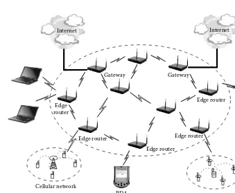
Figure 1.1 Architecture of a wireless mesh network.
1.1 Introduction
existing wireless networking technologies such as IEEE 802.11, IEEE 802.15, IEEE 802.16, and IEEE 802.20 are used in the implementation of WMNs. The IEEE 802.11 is a set of WLAN standards that define many aspects of wireless networking. One such aspect is mesh networking, which is currently un-der development by the IEEE 802.11 Task Group. Recently, there has been growing research and practical interest in WMNs. There are numerous on-going projects on wireless mesh networks in academia, research labs, and companies. Many academic institutions developed their own testbed for research purposes. These efforts are toward developing various applica-tions of WMNs such as home, enterprise, and community networking. As the WMNs use multi-hop paths between client nodes or between a client and a gateway router, the existing protocols for multi-hop ad hoc wireless networks are well suited for WMNs. The ongoing work in WMNs is on increasing the throughput and developing efficient protocols by utilizing the static nature of the mesh routers and topology.
1.1.1 Single-Hop and Multi-Hop Wireless Networks
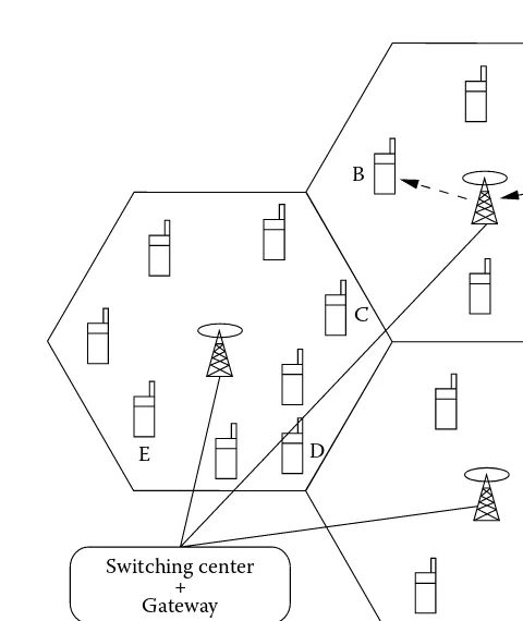
Generally, wireless networks are classified as single-hop and multi-hop networks. In a single-hop network, the client connects to the fixed base station or access point directly in one hop. The well-known examples of single-hop wireless networks are WLANs and cellular networks. WLANs contain special nodes called access points (APs), which are connected to existing wired networks such as Ethernet LANs. The mobile devices are connected to the AP through a one-hop wireless link. Any communication between mobile devices happens via AP. In the case of cellular networks, the geographical area to be covered is divided into cells which are usually considered to be hexagonal. A base station (BS) is located in the center of the cell and the mobile terminals in that cell communicate with it in a single-hop fashion. Communication between any two mobile terminals happens through one or more BSs. These networks are called infrastructure wireless networks because they are infrastructure (BS) dependent. The path setup between two clients (mobile nodes), say node A and node B, is completed through the BS, as shown in Figure 1.2.
E D
Switching center + Gateway
C
A B
Communication path Base station
Mobile node
Figure 1.2 Single-hop network scenario (cellular network).
In the case of single-hop networks, complete information about the clients is available at the BS and the routing decisions are made in a cen-tralized fashion, thus making routing and resource management simple. But it is not the case in multi-hop networks. All the mobile nodes have to coordinate among themselves for communication between any two nodes. Hence, routing and resource management are done in a distributed way.
1.1.2 Ad hoc Networks and WMNs
B A
E F
C
D
Mobile node Wireless link Communication path
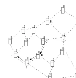
Figure 1.3 Multi-hop network scenario (ad hoc network).
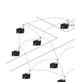
they are operating on battery. This requires energy-efficient networking solutions for ad hoc networks. But in the case of WMNs, mesh routers are assumed to be fixed (or have limited mobility) and form a fixed mesh infra-structure. The clients are mobile or fixed and utilize the mesh routers to communicate to the backhaul network through the gateway routers and to other clients by using mesh routers as relaying nodes. These networks find applications where networks of fixed wireless nodes are necessary. There are several architectures for mesh networks, depending on their applica-tions. In the case of infrastructure backbone networking, the edge routers are used to connect different networks to the mesh backbone and the inter-mediate routers are used as multi-hop relaying nodes to the gateway router, as shown in Figure 1.1. But in the case of community networking, every router provides access to clients and also acts as a relaying node between mesh routers.
1.2 Architecture of WMNs
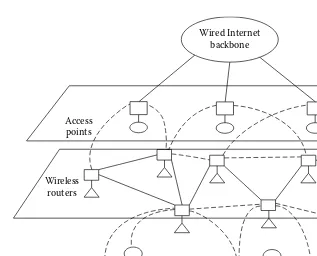
networking. The mesh routers have multiple interfaces of the same or different communications technologies based on the requirement. They achieve more coverage with the same transmission power by using multi-hop communication through other mesh routers. They can be built on general-purpose computer systems such as PCs and laptops, or can be built on dedicated hardware platforms (embedded systems). There are a vari-ety of mesh clients such as laptop, desktop, pocket PCs, IP phones, RFID readers, and PDAs. The mesh clients have mesh networking capabilities to interact with mesh routers, but they are simpler in hardware and software compared to mesh routers. Normally they have a single communication interface built on them. The architecture of WMNs (shown in Figure 1.1) is the most common architecture used in many mesh networking appli-cations such as community networking and home networking. The mesh routers shown have multiple interfaces with different networking technolo-gies which provide connectivity to mesh clients and other networks such as cellular and sensor networks. Normally, long-range communication tech-niques such as directional antennas are provided for communication be-tween mesh routers. Mesh routers form a wireless mesh topology that has self-configuration and self-healing functions built into them. Some mesh routers are designated as gateways which have wired connectivity to the Internet. The integration of other networking technologies is provided by connecting the BS of the network that connects to WMNs to the mesh routers. Here, the clients communicate to the BS of its own network and the BS in turn communicates to the mesh router to access the WMN.
1.3 Applications of WMNs
WMNs introduce the concept of a peer-to-peer mesh topology with wire-less communication between mesh routers. This concept helps to overcome many of today’s deployment challenges, such as the installation of exten-sive Ethernet cabling, and enables new deployment models. Deployment scenarios that are particularly well suited for WMNs include the following:
Campus environments (enterprises and universities), manufacturing, shopping centers, airports, sporting venues, and special events Military operations, disaster recovery, temporary installations, and
public safety
Municipalities, including downtown cores, residential areas, and parks
Carrier-managed service in public areas or residential communities
alternative paths for any pair of source and destination nodes, resulting in quick reconfiguration of the path when there is a path failure. WMNs pro-vide the most economical data transfer coupled with freedom of mobility. Mesh routers can be placed anywhere such as on the rooftop of a home or on a lamppost to provide connectivity to mobile/static clients. Mesh routers can be added incrementally to improve the coverage area. These features of WMNs attract the research community to use WMNs in different applications:
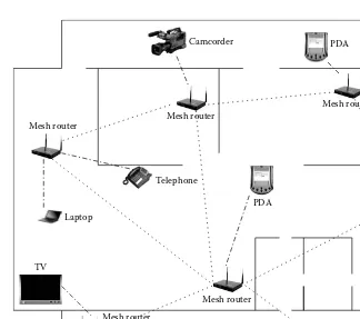
Home Networking: Broadband home networking is a network of home appliances (personal computer, television, video recorder, video camera, washing machine, refrigerator) realized by WLAN technology. The obvious problem here is the location of the access point in the home, which may lead to dead zones without service coverage. More coverage can be achieved by multiple access points connected using Ethernet cabling, which leads to an increase in deployment cost and overhead. These problems can be solved by replacing all the access points by the mesh routers and establishing mesh connectivity between them. This provides broadband con-nectivity between the home networking devices and only a single connection to the Internet is needed through the gateway router. By changing the location and number of mesh routers, the dead zones can be eliminated. Figure 1.4 shows a typical home network using mesh routers.
Laptop
Telephone
Printer
PDA
Mesh router
TV
Mesh router
Mesh router
Mesh router Mesh router
PDA
Mesh router
Wireless link between client and mesh router Desktop
Mesh router
Wireless link between mesh routers
Camcorder
Figure 1.4 Wireless mesh network-based home networking.
catastrophic disk failure. Another advantage is that this technology alleviates the need for routing traffic belonging to community net-working through the Internet. For example, distributed file storage, distributed file access, and video streaming applications in the com-munity share network resources in the WMNs without using the Internet, which improves the performance of these applications. Neighborhood community networks allow faster and easier dissemi-nation of cached information that is relevant to the local community. Mesh routers can be easily mounted on rooftops or windows and the client devices get connected to them in a single hop.
Internet
Home with rooftop mesh router Wireless link between mesh routers Wired backbone connectivity
Gateway
Figure 1.5 Wireless mesh network-based community networking.
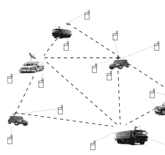
video, and low-cost connectivity between the surveillance devices. The recent advances of WMNs provide high bandwidth and reliable backbone connectivity and an easy way of connecting surveillance devices located in different places with low cost.
Wireless link between mesh routers
Wireless link between mobile terminal and mesh router Mobile terminal with rescue team
Rescue vehicle
Figure 1.6 Wireless mesh network-based rescue operation.
interfaces at the mesh routers, different mobile devices get access to the network. This helps people to communicate with others when they are in critical situations. These networks can be established in less time, which makes the rescue operation more effective.
1.4 Issues in WMNs
compared to ad hoc networks. Due to this, WMNs require considerable work to address the problems that arise in each layer of the protocol stack and system implementation.
1.4.1 Capacity
The primary concern of WMNs is to provide high-bandwidth connectivity to community and enterprise users. In a single-channel wireless network, the capacity of the network degrades as the number of hops or the diameter of the network increases due to interference. The capacity of the WMN is affected by many factors such as network architecture, node density, number of channels used, node mobility, traffic pattern, and transmission range. A clear understanding of the effect of these factors on capacity of the WMNs provides insight to protocol design, architecture design, and deployment of WMNs.
In [2] Gupta and Kumar analytically studied the upper and lower bounds of the capacity of wireless ad hoc networks. They showed that the through-put capacity of the nodes reduces significantly when node density increa-ses. The maximum achievable throughput of randomly placedn identical nodes each with a capacity of W bits/second is (√ W
n∗log(n)) bits/second under a non-interference protocol. Even under optimal circumstances the maximum achievable throughput is only (√W
n) bits/second. The capacity
of the network can be increased by deploying relaying nodes and using a multi-hop path for transmission.
different orthogonal channels. Moreover, when m<nthe capacity bound of a multi-channel multi-radio wireless mesh network depends on the ratio of nand m[7].
1.4.2 Physical Layer
The network capacity mainly depends on the physical layer technique used. There are a number of physical layer techniques available with different operating frequencies and they provide different transport capacity in wire-less communications. Some existing wirewire-less radios even provide multi-ple transmission rates by different combinations of modulation and coding techniques [6]. In such networks, the transmission rate is chosen by link adaptation techniques. Normally, link signal-to-noise ratio (SNR) or carrier-to-noise ratio (CNR) from the physical layer is considered for link adapta-tion, but this alone does not describe the signal quality in the environment like frequency-selective fading channel. To overcome the problems with RF transmission, other physical layer techniques have been used for wireless communications. Some high-speed physical layer techniques are available which improve the capacity of the wireless networks significantly. Some of the techniques for improving the capacity of WMNs are described in this section.
Orthogonal Frequency Division Multiplexing (OFDM): The OFDM technique is based on the principle of Frequency Division Multi-plexing (FDM) with digital modulation schemes. The bit stream to be transmitted is split into a number of parallel low bit rate streams. The available frequency spectrum is divided into many sub-channels and each low bit rate stream is transmitted by modulating over a sub-channel using a standard modulation scheme such as Phase Shift Keying (PSK) and Quadrature Amplitude Modulation (QAM). The primary advantage of OFDM is its ability to work under severe channel conditions, such as multi-path and narrow-band interfer-ence, without complex equalization filters at the transmitter and re-ceiver. The OFDM technique has increased the transmission rate of IEEE 802.11 networks from 11 to 54 Mbps.
is immune to multi-path fading and interference,1 which are com-mon in any radio transmission technique. UWB wireless links have the characteristic that the bandwidth decreases rapidly as the dis-tance increases. On the other hand UWB provides hundreds of non-interfering channels within radio range of each other. Hence, UWB is applicable for only short-range communications such as WPAN. Mesh architecture combined with UWB wireless technology allows a very easy installation of communications infrastructure in offices or homes by deploying many repeater modules every 10 meters. As these repeater modules require power to operate on, they have to be placed with ceiling lights or floor power boxes. The IEEE 802.15 TG4a standard for WPAN uses a UWB physical layer technique con-sisting of a UWB impulse radio (operating in unlicensed UWB spec-trum) and a chirp spread spectrum (operating in unlicensed 2.4 GHz spectrum).
Multiple-Input Multiple-Output (MIMO): The use of multiple an-tennas at the transmitter and receiver, popularly known as MIMO wireless, is an emerging, cost-effective technology that makes high bandwidth wireless links a reality. MIMO significantly increases the throughput and range with the same bandwidth and overall trans-mission power expenditure. This increase in throughput and range is by exploiting the multi-path propagation phenomena in wire-less communications. In general, the MIMO technique increases the spectral efficiency of a wireless communications system. It has been shown by Telatar that the channel capacity (a theoretical up-per bound on system throughput) for a MIMO system increases as the number of antennas increases, proportional to the minimum of transmitter and receiver antennas [8]. MIMO can also be used in conjunction with OFDM and is part of the IEEE 802.16 standard. Smart Antenna: The smart antenna technique improves the capacity
of wireless networks by adding the directionality for transmission and reception of signals at the transmitter and receiver antenna. This also helps in increasing energy efficiency. In cellular networks, due to complexity and cost of smart antennas, it is implemented in BS alone. The directional antenna system is actively researched in ad hoc networks also. There are some directional antenna sys-tems available that can be tuned to certain directions by electronic beam forming. This technique improves the performance of wireless
1In RF transmission, when the transmitted signal is reflected by mountains or buildings
networks by reducing interference between the transmissions of dif-ferent nodes in the network. But the use of a directional antenna necessitates special MAC (Medium Access Control) protocols to sup-port directionality in transmission and reception.
1.4.3 Medium Access Scheme
The MAC (Medium Access Control) protocols for wireless networks are lim-ited to single-hop communication while the routing protocols use multi-hop communication. The MAC protocols for WMNs are classified into single-channel and multi-single-channel MAC. They are discussed in this section.
Single-Channel MAC: There are several MAC schemes which use single-channel for communication in the network. They are further classified as (1) contention-based protocols, (2) contention-based protocols with a reservation mechanism, and (3) contention-based protocols with a scheduling mechanism.
Contention-based protocols: These protocols have a contention-based channel access policy among the nodes contending for the channel. All the ready nodes in the network start contend-ing for the channel simultaneously and the winncontend-ing node gains access to the channel. As the nodes cannot provide guaranteed bandwidth, these protocols cannot be used in carrying real-time traffic, which requires QoS (quality of service) guarantees from the system. Some of the contention-based protocols are MACAW (a media access protocol for Wireless LANs) [9], FAMA (Floor Acquisition Multiple Access protocol) [10], BTMA (Busy Tone Multiple Access protocol) [11], and MACA-BI (Multiple Access Collision Avoidance By Invitation) [12].
protocol) [14], HRMA (Hop Reservation Multiple Access proto-col) [15], and RTMAC (Real-Time Medium Access protoproto-col) [16]. Contention-based protocols with scheduling mechanism: These protocols focus on packet scheduling at nodes and also schedul-ing nodes for access to the channel. The schedulschedul-ing is done in such a way that all nodes are treated fairly and no node is starved of bandwidth. These protocols can provide priori-ties among flows whose packets are queued at nodes. Some of the existing scheduling-based protocols are DWOP (Distributed Wireless Ordering Protocol) [17], DLPS (Distributed Laxity-based Priority Scheduling) [18], and DPS (Distributed Priority Schedul-ing) [19].
Contention-based protocols that use single-channel for communica-tion cannot completely eliminate contencommunica-tion for the channel. In the case of WMNs the end-to-end throughput significantly reduces due to the accumulating effect of the contention in the multi-hop path. Further, an ongoing transmission between a pair of nodes refrains all the nodes which are in a two-hop neighborhood of nodes partic-ipating in the transmission from transmitting on the channel during the transmission period. To overcome these problems multi-channel MAC and multi-channel multi-radio MAC protocols are proposed. Multi-Channel MAC (MMAC): Multi-channel MAC [20] is a link layer
orthogonal channel, thereby increasing the number of simultaneous transmissions in the network. Though MMAC increases the through-put, there are some drawbacks with it. When a node has to send a packet to multiple destinations, it can send only to one destination in a beacon interval, because the nodes have to negotiate during the ATIM window in the control channel. Due to this restriction the per-packet delay increases significantly. MMAC does not have any scheme for broadcasting.
Slotted Seeded Channel Hopping protocol (SSCH) is another multi-channel link layer protocol using a single transceiver [21]. SSCH is implemented in software over an IEEE 802.11-compliant wireless Network Interface Card (NIC). SSCH uses a distributed mechanism for coordinating the channel switching decision. By this channel hopping at each node, packets of multiple flows in the interfering range of each other are transmitted simultaneously in an orthogonal channel. This improves the overall capacity of the multi-hop wire-less network if the network traffic pattern has multiple flows in the interfering range of each other. Each node in the network finds the channel hopping schedule for it and schedules the packets within each channel. Each node transmits its channel hopping schedule to all its neighboring nodes and updates its channel hopping schedule based on traffic pattern. SSCH yields significant capacity improve-ment in both single-hop and multi-hop network scenarios.
Multi-Radio Multi-Channel MAC: In the application scenarios where the cost of the node and power consumption are not big issues, nodes can be provided with multiple wireless interfaces which are tuned to non-overlapping channels and can communicate simultane-ously with multiple neighboring nodes. If nodes have multiple inter-faces, then the MAC protocol has to handle the orthogonal channel assignment to each interface and schedule the packets to the ap-propriate interface. The Multi-radio Unification Protocol (MUP) [22] is one such protocol to coordinate the operation of the multiple wireless NICs tuned to non-overlapping channels. MUP works as a virtual MAC which requires no changes to the higher layer proto-cols and works with other nodes which do not have MUP. So these type of nodes can be added incrementally even after deployment. For the higher layer protocols the MUP looks like a single MAC run-ning. It monitors the channel quality on each of the NICs to each of its neighbors. When the higher layer protocol sends packets to the MUP, it selects the right interface to forward the packets.
where interfaces are assigned dynamically for short spans of time. The channel assigned to fixed interfaces is called a fixed channel and that assigned to switchable interfaces is called a switchable channel. Each node has both a fixed channel and a switchable channel. Dur-ing a flow initiation, each node finds the channel in the switchable interface based on the fixed channel of the next-hop neighbor to transmit the data to it. Once the switchable interfaces are switched to a channel there is no need for switching the channel for the sub-sequent packets for that flow unless another flow requires channel switching on the switchable interface.
1.4.4 Routing
There are numerous routing protocols proposed for ad hoc networks in the literature. Because WMNs are multi-hop networks, the protocols designed for ad hoc networks also work well for WMNs. The main objective of those protocols is quick adaptation to the change in a path when there is path break due to mobility of the nodes. Current deployments of WMNs make use of routing protocols proposed for ad hoc networks such as AODV (Ad hoc On-Demand Distance Vector) [25], DSR (Dynamic Source Routing) [26], and TBRPF (Topology Broadcast based on Reverse Path Forwarding) [27]. However, in WMNs the mesh routers have minimal mobility and there is no power constraint, whereas the clients are mobile with limited power. Such difference needs to be considered in developing efficient routing protocols for WMNs. As the links in the WMNs are long lived, finding a reliable and high throughput path is the main concern rather than quick adaptation to link failure as in the case of ad hoc networks.
1.4.4.1 Routing Metrics for WMNs
links usually have asymmetric loss rate as reported in [29]. Hence, new routing metrics based on the link quality are proposed in the literature. They are ETX (Expected Transmission Count), per-hop RTT (Round-Trip Time), and per-hop packet pair. Couto et al. proposed ETX to find a high throughput path in WMNs [28]. The metric ETX is defined as the expected number of transmissions (including retransmissions) needed to successfully deliver a packet over a link. As per IEEE 802.11 standard, a successful transmission requires acknowledgment back to the sender. ETX considers transmission loss probability in both directions, which may not be equal as stated earlier. All nodes in the network compute the loss probability to and from its neighbors by sending probe packets. If pf and pr are respectively
the loss probability in forward and reverse direction in a link, then the probability that a packet transmission is not successful in a link is given by
p = 1−(1− pf)(1− pr). The expected number of transmissions on that
link is computed as ETX = 1−1p. In [30] the routing metrics based on link
quality are compared with the hop count metric. The routing metric based on link quality performs better than hop count if nodes are stationary. The hop count metric outperforms the link quality metric if nodes are mobile. The main reason for this is that the ETX metric cannot quickly track the changes in the value of the metric. If the nodes are mobile, the ETX value changes frequently as the distance between the nodes changes.
As stated earlier, to improve the throughput the multi-radio multi-channel architecture is used in WMNs. In this case the routing metric based on link quality alone is not sufficient. It should also consider the channel diversity on the path. A new routing metric WCETT (Weighted Cumulative Expected Transmission Time) is proposed in [31], which takes both link quality and channel diversity into account. The link quality is measured by a per-link metric called ETT (Expected Transmission Time; expected time to transmit a packet of a certain size over a link). If the size of the packet is S and the bandwidth of the link is B, then ETT = ETX∗ SB. The channel
diver-sity in the path is measured as follows. If Xj is the sum of ETTs of the
links using the channel j in the path, then channel diversity is measured as max1≤j≤kXj, wherek is the number of orthogonal channels used. The
path metric for pathpwithnlinks andkorthogonal channels is calculated as
WCETT(p)=(1−β)∗ n
i=1
ETTi+β∗max1≤j≤kXj,
whereβ is a tunable parameter subject to 0 ≤β≤1. WCETT can achieve a good trade-off between delay and throughput as it considers both link quality and channel diversity in a single routing metric.
interference on the path. In [32], a new routing metric MIC (Metric of In-terference and Channel switching) is proposed for channel multi-radio WMNs. This new metric considers the quality of links, inter flow interference, and intra flow interference altogether. This metric is based on Interference-Aware Resource Usage (IRU) and Channel Switching Cost (CSC) metrics to find the MIC for a given path. IRU captures the differences in the transmission rate and the loss ratios of the wireless link and the inter flow interference. The IRU metric for a link k which uses channelc
is calculated as IRUk(c)=ETTk(c)∗Nk(c), whereETTk(c) is the expected
transmission time of the link kon the channelc, and Nk(c) is the number
of nodes interfering with the transmission of the linkk on channelc. The CSC metric captures the intra flow interference along the path. CSC for a node i is assigned a weight w1 if links in the path connected to it have different channels assigned, andw2 if they are the same, 0≤w1 <w2. The path metric for a given pathp, MIC(p), is calculated as follows:
MIC(p)=α∗ (link l ε p)
IRUl+
(node i ε p)
CSCi.
Hereαis a positive factor which gives a trade-off between benefits of IRU and CSC.
1.4.4.2 Routing Protocols for WMNs
In [30], the authors proposed an LQSR (Link Quality Source Routing) pro-tocol. It is based on DSR and uses ETX as the routing metric. The main difference between LQSR and DSR is getting the ETX metric of each link to find out the path. During the route discovery phase, the source node sends a Route Request (RREQ) packet to neighboring nodes. When a node receives the RREQ packet, it appends its own address to the source route and the ETX value of the link in which the packet was received. The des-tination sends the Route Reply (RREP) packet with a complete list of links along with the ETX value of those links. Because the link quality varies with time, LQSR also propagates the ETX value of the links during the data transmission phase. On receiving a data packet, an intermediate node in the path updates the source route with the ETX value of the outgoing link. Upon receiving the packet, the destination node sends an explicit RREP packet back to the source to update the ETX value of links in the path. LQSR also uses a proactive mechanism to update the ETX metric of all links by piggybacking Link-Info messages to RREQ messages occasionally. This Link-Info message contains the ETX value of all the links incident on the originating node.
propagating the link metric to other nodes in the network in MR-LQSR are the same as that in the DSR protocol. But assigning the link weight and finding the path weight using the link weight are different from DSR. DSR uses equal weight to all links in the network and implements the shortest path routing. But MR-LQSR uses a WCETT path metric to find the best path to the destination.
In [32], the authors showed that, if a WCETT routing metric is used in a link state routing protocol, it is not satisfying the isotonicity property of the routing protocol and leads to formation of routing loops. To avoid the formation of routing loops by the routing metrics, they proposed Load and Interference Balanced Routing Algorithm (LIBRA) [32], which uses MIC as the routing metric. In LIBRA a virtual network is formed from the real network and decomposed the MIC metric into isotonicity link weight as-signment on the virtual network. The objective of MIC decomposition is to ensure that LIBRA can use efficient algorithms such as Bellman–Ford or Dijkstra’s algorithm to find the minimum weight path on the real network without any forwarding loops.
1.4.5 Transport Layer
There are several reliable transport protocols proposed for ad hoc networks. Some of them are modified versions of TCP (Transmission Control Protocol) that work well in ad hoc networks and others are designed specifically for an ad hoc network scenario from scratch.
TCP is the de facto standard for end-to-end reliable transmission of data on the Internet. TCP was designed to run efficiently on wireline networks. Using the TCP protocol on a wireless network degrades the performance of the network in terms of reduction in throughput and unfairness to the connections. This degradation in performance is due to the following rea-sons. The Bit Error Rate (BER) in wireless networks is very high compared to wireline networks. Frequency of path break in wireless networks is high due to mobility of nodes in ad hoc networks. If the packets get dropped in the network due to these reasons, the TCP sender misinterprets this event as congestion and triggers the congestion control mechanism to reduce the congestion window size. This reduces the effective throughput of the network.
source regarding the status of a path. In ELFN (Explicit Link Failure Notification) [33], the intermediate node informs the sender about the link failure explicitly. When the sender is informed that the link has failed, it disables its retransmission timer and enters into standby mode. In the standby mode the sender probes the network to check if the network connection is re-established by sending a packet from the congestion window periodically. Upon receiving an ACK from the receiver, i.e., after the connection is established, the sender re-sumes its normal operation. In TCPF (TCP-Feedback) [34], when an intermediate node detects path break, it sends an RFN (Route Fail-ure Notification) message to the TCP sender. On receiving an RFN message, the TCP sender goes to snooze state. In this state the TCP sender stops sending packets and freezes all its variables such as retransmission buffer, congestion window, and packet buffer. Once the route is established again, the intermediate node sends an RRN (Route Re-established Notification) message to the sender. Upon receiving an RRN message from an intermediate node, the sender resumes its transmission using the same variable values that were being used prior to interruption. To avoid an infinite wait for an RRN message, TCPF uses a route failure timer, which is the worst-case route re-establishment time.
Other Transport Protocols for Wireless Networks: In [35], a transport protocol for wireless networks was proposed by not modifying the existing TCP protocol. This is done by introducing a thin layer called ATCP between the network layer and transport layer and it is invis-ible to transport layer. This makes nodes with ATCP and without ATCP interoperable with each other. ATCP gets information about congestion in the network from the intermediate nodes through ECN (Explicit Congestion Notification) and ICMP messages. Based on this, the source node distinguishes congestion and non-congestion losses and takes the appropriate action.
When the TCP sender identifies any network partitioning, it goes into persist state and stops all the outgoing transmissions. When the TCP sender notices any loss of packets in the network
due to channel error, it retransmits the packet without invoking any congestion control.
When the network is truly congested, it invokes the TCP con-gestion control mechanism.
1.4.6 Gateway Load Balancing
Internet. As many clients in the network generate traffic to the gateway, the available bandwidth should be utilized effectively. The traffic generated by client nodes aggregates at gateway nodes in the WMN. If some of the gate-way nodes are highly loaded and other gategate-way nodes are lightly loaded, it creates load imbalance between gateway nodes, which leads to packet loss and results in a degradation in network performance. Hence, load bal-ancing across gateway nodes in WMNs improves bandwidth utilization and also increases network throughput.
Load balancing across gateway nodes is obtained by distributing the traffic generated by the network to the backhaul network through all gate-way nodes in the WMNs. The load balancing across multiple gategate-way nodes can be measured quantitatively by a metric called Index of Load Balance (ILB) [36] which is calculated as follows.
Load index (LI) of a gatewayiis defined as the fraction of the gateway’s backhaul link utilized by a given nodek,L I(i)=
k∈Nβk(i)∗Tk
C(i) , whereβk(i) is the fraction of node k’s traffic that is sent through gatewayi, Tk is the
total traffic generated by node k, andC(i) is the capacity of the backhaul link connected to the gateway node i. The LI value ranges from 0 to 1, with 1 representing 100 percent loaded gateway. The ILB of the network is calculated as
ILB= max{LI(i)} −min{LI(i)} max{LI(i)}
Therefore a perfectly balanced network has ILB equal to zero and a highly imbalanced network has ILB equal to one. The objective of all load bal-ancing techniques is to obtain ILB values as small as possible. Several tech-niques for load balancing across gateways were proposed in the literature. Some of them are discussed in this section.
Moving Boundary-Based Load Balancing: A flexible boundary is de-fined for each gateway and the nodes which fall in the boundary are directed to communicate through that gateway. To adopt to varia-tions in the traffic, the region of boundary is periodically redefined. The boundary can be defined in two different ways: (1) in a shortest path-based moving boundary approach, the boundary region for a gateway node is defined by distance of the node from the gateway, and (2) in a load index-based moving boundary approach, the gate-ways announce their load Index and the nodes join lightly loaded gateways. In this scheme the lightly loaded gateway serves more nodes and the heavily loaded gateway serves fewer nodes.
load balancing is that no clear boundary is defined. This can be done in both a centralized and distributed way. In the centralized method, a central server assumes the responsibility of assigning the gateway to the nodes. The central server collects the complete infor-mation about the gateway nodes and traffic requirements of all the nodes and then allocates nodes to the gateways. In the distributed method, a logical network is formed by the gateway nodes. Each node is associated with a gateway node known as a dominating gate-way through which traffic generated by this node reaches the Inter-net. The nodes in the network periodically update their dominating gateway about their traffic demand. The gateway nodes exchange information about their load and capacity information through the logical network. When a gateway is highly loaded, hand-over takes place, i.e., the gateway delegates some nodes to other gateways which are lightly loaded.
Probabilistic Stripping-Based Load Balancing: In the techniques dis-cussed above, each node in the network utilizes only one gateway, which may not lead to perfect load balancing among the gateways. In a probabilistic stripping-based load balancing scheme, each node utilizes multiple gateways simultaneously, which gives perfect load balancing theoretically. In this technique each node identifies all the gateway nodes in the network and attempts to send a fraction of its traffic through every gateway. Hence, the total traffic is split among multiple gateways. This technique is applicable in the case where the load can be split for sending through multiple gateways.
1.4.7 Security
As mentioned earlier, due to the unique characteristics of WMNs, they are highly vulnerable to security attacks compared to wired networks. Design-ing a foolproof security mechanism for WMNs is a challengDesign-ing task. The security can be provided in various layers of the protocol stack. Current security approaches may be effective against a particular attack in a spe-cific protocol layer, but they lack a comprehensive mechanism to prevent or counter attacks in different protocol layers. The following issues pose difficulty in providing security in WMNs:
range of mesh routers or a mesh client. For example, if you have a WMN and so does your neighbor, then there is a scope for either snooping into private data or simply hogging the available band-width of a neighboring, but alien node.
Lack of Association: In WMNs, the mesh routers form a fixed mesh topology which forms a backbone network for the mobile clients. Hence, the clients can join or leave the network at any time through the mesh routers. If no proper authentication mechanism is provided for association of nodes with WMNs, an intruder would be able to join the network quite easily and carry out attacks.
Physical Vulnerability: Depending on the application of WMNs, the mesh routers are placed on lampposts and rooftops, which are vul-nerable to theft and physical damage.
Limited Resource Availability: Normally, the mesh clients are limited in resources such as bandwidth, battery power, and computational power. Hence, it is difficult to implement complex cryptography-based mechanisms at the client nodes. As mesh routers are resource rich in terms of battery power and computational power, security mechanisms can be implemented at mesh routers. Due to wireless connectivity between mesh routers, they also have bandwidth con-straints. Hence, the communication overhead incurred by the secu-rity mechanism should be minimal.
1.4.8 Power Management
The energy efficiency of a node in the network is defined as the ratio of the amount of data delivered by the node to the total energy expended. Higher energy efficiency implies that a greater number of packets can be transmitted by the node with a given amount of energy resource. The main reasons for power management in WMNs are listed below.
Power Limited Clients: In WMNs, though the mesh routers do not have limitations on power, clients such as PDAs and IP phones have limited power as they are operated on batteries. In the case of Hybrid WMNs, clients of the other networks that are connected to them, such as sensor networks, can be power limited. Hence, power efficiency is of major concern in WMNs.
power decreases the interference among nodes, which in turn in-creases the number of simultaneous transmissions in the network. Channel Utilization: In multi-channel WMNs, the reduction in
trans-mission power increases the channel reuse, which increases the number of simultaneous transmissions that improves the overall ca-pacity of the network. Power control becomes very important for CDMA-based systems in which the available bandwidth is shared by all the users. Hence, power control is essential to maintain the required signal-to-interference ratio (SIR) at the receiver and to increase the channel reusability.
Several power efficient MAC protocols and power-aware routing proto-cols are proposed for ad hoc networks to efficiently utilize limited energy resource available in mobile nodes. These protocols consider all the nodes in the network power limited. In WMNs, some nodes are power limited and others have no limitation on power. So, when a power-efficient pro-tocol is used in WMNs, it would not utilize the resource-rich mesh routers to reduce power consumption on power-limited mesh clients. Hence, new protocols are required which consider both types of nodes and efficiently utilize the power of the client nodes.
1.4.9 Mobility Management
In WMNs the mobile clients get network access by connecting to one of the mesh routers in the network. When a mobile client moves around the network, it switches its connectivity from one mesh router to another. This is called hand-off or hand-over. In WMNs the clients should have capability to transfer connectivity from one mesh router to another to implement hand-off technique efficiently. Some of the issues in handling hand-hand-offs in WMNs are discussed below.
Optimal Mesh Router Selection: Each mesh client connects to one of the mesh routers in the WMN. Normally, each mesh client chooses the mesh router based on the signal strength it receives from the mesh routers. When a mobile client is in the transmission range of multiple mesh routers, it is very difficult to clearly decide to which mesh router the mobile client must be assigned.
the client weakens. Here the mesh router requires information from other mesh routers about the signal strength they receive from the particular client and deduces to which mesh router the connection should be handed over.
Hand-Off Delay: During hand-off, the existing connections between clients and network get interrupted. Though the hand-off gives con-tinuous connectivity to the roaming clients, the period of interrup-tion may be several seconds. All ongoing transmissions of the client are transferred from the current mesh router to a new mesh router. The time taken for this transfer is called hand-off delay. The delay of a few seconds may be acceptable for applications like file transfer, but for applications that require real-time transport such as interac-tive VoIP (Voice-over-IP) or videoconferencing, it is unacceptable. Quality of Hand-Off: During hand-off some number of packets may
be dropped due to hand-off delay or interruption on the ongoing transmission. The quality can be measured by the number of packets lost per hand-off. A good quality hand-off provides a low packet loss per hand-off. The acceptable amount of packet loss per hand-off differs between applications.
The hand-off mechanisms in cellular networks are studied in [37] and [38]. When a user moves from the coverage area of one BS to the adjacent one, it finds an uplink–downlink channel pair from the new cell and drops the link from the current BS. In WLANs, whenever a client moves from one AP to another, the link has to be reconfigured manually. In this case, all ongoing connections are terminated abruptly. It may be applicable in LAN environments as the clients have limited mobility around a limited area. But in the case of WMNs, the mesh clients may constantly roam around different mesh routers. Here, manual reconfiguration of mesh clients, whenever the client moves from one mesh router to another, is a difficult task. So the hand-off has to be done automatically and transparently. The users should not feel that the existing connections are transferred from one mesh router to another. For applications such as VoIP and IPTV in WMNs, sophisticated and transparent hand-off techniques are required.
Mobility: In many applications of WMNs, the mesh routers form a fixed backbone network by placing the mesh routers at fixed loca-tions such as rooftops and lampposts. So the mesh routers are con-sidered immobile, but the clients in the mesh network are highly mobile and can be connected to any mesh router based on signal strength received from different mesh routers.
Resource Availability: Normally, mesh routers are operated with electric power rather than battery power. They are placed in loca-tions where the powerline is available, so the mesh routers do not have energy constraints. But the clients are operating with battery power and are considered energy constrained.
The existing protocols for ad hoc networks consider the characteristics of all nodes in the same way. The energy-aware protocols consider all nodes in the network battery operated. The protocols that take into account the mobility of nodes in the network consider all nodes in the network mobile. For example, a routing protocol designed for networks with high mobility and limited power when used in WMNs does not utilize the limited mobility and rich energy resource nature of mesh routers. Hence, it fails to improve the performance of WMNs. But due to the characteristics of mesh routers, the routing protocols become simple and efficient. So WMNs need efficient protocols that consider the differences between the mesh routers and mesh clients to improve the performance of WMNs.
1.4.11 Integration with Other Network Technologies
The integration of WMNs with other existing network technologies such as cellular, WiFi, WiMAX, WiMedia, and sensor networks can be achieved by bridging functions at the mesh routers. These bridging functions can be provided by adding network interfaces corresponding to the networking technology that the mesh router has to support. There are several issues to be addressed in integrating multiple networking technologies with WMNs:
Complexity of Mesh Router: The integration of multiple networking technologies with the mesh network increases the complexity of the mesh routers. For each networking technology to be supported by a mesh router, a network interface should be provided. This increases the hardware and software complexity of the mesh routers.
Services Provided by Integrated WMNs: The services provided by different networking technologies are different. Services not pro-vided by IEEE 802.11 can be propro-vided by cellular networks. Simi-larly the services provided by sensor networks cannot be provided by cellular networks. The integration of other networking technolo-gies with WMNs provides many services to the users that are not provided by WMNs alone. Depending on the service requirement, the required networking technologies can be integrated with WMNs. Inter-Operability of Network Technologies: The protocols for differ-ent network technologies are independdiffer-ent and operating them to-gether is a difficult task. For example, the routing protocols used by a cellular network and an IEEE 802.11 network are not the same. Fur-ther, the MAC protocols used by different networking technologies are not inter-operable. So the inter-operability of different network-ing technologies necessitates new software architectures or middle-ware implementations over the mesh networking platform.
Though the integration of multiple networking technologies with WMNs is a difficult job, the services rendered by this necessitate the researchers to come up with a feasible solution. The development of new network architectures and middleware solutions may solve some of these problems. The problem of implementation of many network interfaces in a single mesh router can be solved by using defined radios. The software-defined radio system is a software-based communication system for mod-ulation and demodmod-ulation of radio signal. This is done by advanced signal processing techniques implemented in a digital computer or in a reconfig-urable digital electronic system. This technique produces different radios that can receive and transmit a new form of radio protocol just by run-ning different software rather than desigrun-ning new hardware. This helps in reducing the number of networking interfaces in mesh routers.
1.4.12 Deployment Considerations
Scenario of Deployment: The capability required for deployments of different WMNs is not the same. For example, WMN deployment for community networking to share network resources among people is not the same as for rescue operations. Some of the deployment scenarios in which the deployment issues vary are
a backbone communication network is essential. Most impor-tantly, the network should provide support for time-sensitive traffic such as voice and video. The network should also provide support for different networking technologies to communicate using this network. Hence, the mesh routers should provide in-terfaces for other existing technologies which allow people to communicate using any communication equipment they have. Commercial Broadband Access Deployment: The aim of this
deployment is to provide an alternate network infrastructure for wireless communications in urban areas and areas where a tradi-tional cellular BS cannot handle the traffic volume. This scenario assumes significance as it provides very low cost per bit trans-ferred compared to the cellular network infrastructure. Another major advantage of this application is the resilience to failure of a certain number of nodes. Addressing, configuration, position-ing of relayposition-ing nodes, redundancy of nodes, and power sources are the major issues in deployment. Billing, provisioning of QoS, security, and handling mobility are major issues that the service provider needs to address.
Home Network Deployment: The deployment of a home area network needs to consider the limited range of the devices that are to be connected by the network. Given the short transmis-sion ranges of a few meters, it is essential to avoid network partitions. Positioning of mesh routers at certain key locations of a home area network can solve this problem; also network topology should be decided so that every mesh router is con-nected through multiple neighbors for availability.
Cost of Deployment: The commercial deployment of a communi-cations infrastructure using a WMN essentially eliminates the re-quirement of laying cables and maintaining them. Hence, the cost of deployment is much less than that of the wired infrastructure. Only the mesh routers have to be placed in appropriate locations for efficient coverage. The mesh router manufacturers are providing mesh routers for outdoor placements. Mesh routers can be placed on poles on the street, which reduces the cost of deployment of mesh networks.
Short Deployment Time: Compared to any wired communication infrastructure, WMNs have less deployment time due to absence of laying cables. Wiring the dense urban region is extremely difficult and time consuming, in addition to the inconvenience caused. Mesh routers can be placed based on the area of coverage and number of active users in the area. They can be deployed even on rooftops, provided that electrical power is available.
Auto-Configurability: The incremental deployment of mesh networks to increase the coverage area or number of users leads to changes in topology of the network at later stages. The lossy nature of the wire-less medium changes due to environmental changes, which leads the routing protocols to change the path very often. Due to this, the network needs re-configuration very often.
Operational Integration with Other Infrastructure: Operational inte-gration with other networking technologies such as satellite, cellular, and sensor networks can be considered to improve the performance or provide additional services to the end users. In the commercial world, the WMNs that service a given urban region can interoperate with the cellular infrastructure to provide better QoS and smooth hand-offs across the networks. Hand-offs to a different network can be done to avoid call drops when a mobile node with an active call moves into a region where service is not provided by the current network.
Area of Coverage: In most of the cases, the area of coverage of WMNs is determined by the nature of application for which the net-work is set up. For example, for home netnet-works the coverage of the mesh routers is within the home or within the room in which the router is placed. But in the case of wireless service providers, mesh routers should be covering a number of homes on a street. Long-range communication by fixed mesh routers can be achieved by means of directional antennas. The mesh routers’ and mobile clients’ capabilities such as transmission range and associated hard-ware, softhard-ware, and power source should match the area of coverage required.
of them does not lead to lack of service in that area. In such cases, redundant inactive mesh routers can be placed in such a way that, in the event of failure of active mesh routers, the redundant mesh routers can take over their responsibilities.
Choice of Protocols: The choice of protocols at different layers of the protocol stack is to be done by taking into consideration the de-ployment scenario. The MAC protocol should ensure provisioning of security at link level for military applications. The routing pro-tocol also should be selected with care. In the case of integration of different networking technologies, end-to-end paths may have different types of nodes with different capabilities. It requires rout-ing protocols that consider the resource limitations of the nodes. At the transport layer, depending upon the environment in which the WMN is deployed, the connection-oriented or connectionless protocols should be chosen. If the clients connected to the WMN are highly mobile, a frequent hand-off of the clients with the mesh routers takes place. This causes the higher-layer protocols to take necessary action appropriately; also, packet loss arising due to con-gestion, channel error, link break, and network partition is to be handled differently in different applications. The timer values at dif-ferent layers of the protocol stack should be adapted to the deploy-ment scenario.
1.5 WMN Deployments/Testbeds
For the deployment of WMNs to be viable, they must be easy to install. This is particularly important for home applications where people are unwill-ing to install highly technical networks. A number of IEEE standards such as 802.11, 802.15, 802.16, and 802.20 have emerged recently for wireless networks. Many task groups have been working on standardization of the protocols for WMNs, which leads to the development and interoperability of mesh networking products from different vendors. Many testbeds have been established to carry out research and development work in WMNs.
1.5.1 IEEE 802.11 WMNs
2.4 GHz ISM band at data rates of 5.5 and 11 Mbps. IEEE 802.11a [5] operates in the 5 GHz band (unlicensed national information infrastructure band). It supports data rates up to 54 Mbps. IEEE 802.11e deals with the require-ments of time-sensitive applications such as voice and video. IEEE 802.11g aims at providing the high data rate of IEEE 802.11a in the ISM band. Under the 802.11 standard, mobile clients can operate in infrastructure mode and ad hoc mode. In infrastructure mode a mobile client communicates with others through one or more APs. In ad hoc mode mobile clients can com-municate directly with each other without using an AP. The set of mobile clients associated with a given AP is called a Basic Service Set (BSS). A BSS is the basic building block of the network. BSSs are connected by means of a Distribution System (DS) to form an extended network. Any logical point through which non-IEEE 802.11 packets enter the system is called a portal. Portals are also used for integrating wireless networks with the existing wired network. The BSS, DS, and portals together with the mobile clients they connect constitute the Extended Service Set (ESS). Another working group in IEEE 802.11 [3], called 802.11s, has been formed recently to stan-dardize the ESS for mesh networking. It defines architecture and protocols based on IEEE 802.11 MAC to create an 802.11-based Wireless Distribution System (WDS). This WDS supports both broadcast, multicast, and unicast delivery using radio-aware metrics over self-configuring multi-hop topolo-gies. There are two main proposals for 802.11s by SEEMesh and Wi-Mesh. The main features of these proposals are as follows:
Supports single and multiple radios.
With authentication and key management procedures, it provides secure key distribution and secure exchange of routing information, supporting centralized and distributed models.
Supports QoS and power-efficiency-aware routing with a WDS four-addressing extension that supports dynamic auto-configuration of MAC-layer data delivery.
Enables multiple routing algorithms for MAC address-based forward-ing with a simple Hello message for mesh discovery and association and supporting extended mesh discovery.
1.5.2 IEEE 802.15 WMNs
The IEEE 802.15 Task Group 5 is chartered to determine the mechanisms that must be present in the PHY and MAC layers of WPANs to enable mesh networking. A mesh network is a PAN that employs one of the two connection arrangements, full mesh topology or partial mesh topology. In the full mesh topology, all nodes are in the transmission range of one another, i.e., each node can communicate with other nodes in one hop. In partial mesh topology, nodes in the network have one-hop communication with a few nodes only. The 802.15 mesh networks have the following capabilities:
Extension of network coverage without increasing transmit power or receiver sensitivity
Enhanced reliability via route redundancy Easier network configuration
Better battery life of device due to fewer retransmissions
1.5.3 IEEE 802.16 WMNs
the next transmission time. If it fails, the node selects the next transmis-sion slot and continues contention until it wins. For a connection setup, a request/grant/confirm three-way handshake procedure is used.
1.5.4 Academic Research Testbeds
Many academic research institutes established testbeds to study realistic behavior of WMNs. Some of them are discussed in this section.
MIT Roofnet [44–46]: MIT Roofnet is an 802.11b multi-hop network designed to provide broadband Internet connectivity to users in apartments of Cambridge, MA. It has about 50 nodes connected through 802.11b interfaces in multi-hop fashion and connected to the Internet through an Ethernet interface available in the apart-ments. Research on Roofnet includes link-level measurements of 802.11 interfaces, finding high-throughput routes in the face of lossy links, adaptive bit-rate selection, and developing new protocols which take advantage of radio’s unique properties. The main feature of Roofnet is that it is an unplanned network, i.e., no configuration or planning is required.
CalRadio-I [47]: California Institute for Telecommunications and Information Technology developed CalRadio-I, which is a radio/ networking test platform for wireless research and development. This is a single integrated, wireless networking test platform which provides a simple, low-cost platform development from the MAC layer to a higher layer. All the MAC functionalities are coded in C language that runs on the DSP processor. Any modification to the MAC protocol can be done and tested in it. CalRadio-I functions as a test instrument, an AP, and as a WiFi client.
(Wireless Sensor and Actor Networks), next-generation Internet, and WiMAX with WMNs testbed leads to design and evaluation of pro-tocols for heterogeneous wireless networks.
UCSB MeshNet [49]: The University of California, Santa Barbara, de-ployed an experimental testbed on their campus. It consists of 25 nodes equipped with multiple IEEE 802.11a/b/g wireless radios. The main objective of the testbed is to design protocols for the robust operation of multi-hop wireless networks. Specifically, the testbed is being used to conduct research on scalable routing protocols, efficient network management, multimedia streaming, and QoS for multi-hop wireless networks.
1.5.5 Industrial Research in WMNs
Many companies started research in WMNs on their own and in collab-oration with academic research institutions. Some of them recently came up with mesh networking products for implementing mesh network-based applications. In this section some of the industries working toward research aspects of WMNs and some of the industries providing mesh networking products are discussed.
layers as well. This implementation supports Ethernet-like physical link layers (e.g., 802.11 and 802.3), but the architecture accommo-dates link layers with arbitrary addressing and framing conventions. The virtual MCL network adapter can multiplex several physical net-work adapters, so the ad hoc netnet-work can be extended across het-erogeneous physical links. Third, the design can support other ad hoc routing protocols as well.
Intel [51]: A wide variety of research and development efforts at Intel are geared toward understanding and addressing the technical chal-lenges for realizing multi-hop mesh networks. Intel’s Network Archi-tecture Lab is aimed at overcoming many of the challenges faced by WMNs. They developed low-cost and low-power AP prototypes or nodes to enable further research on security, traffic characterization, dynamic routing and configuration, and QoS problems. Intel is also working with other industries to develop standards and protocols that support WMNs and enable interoperability between products from multiple vendors. Intel is working to simplify the entire instal-lation process, including network node placement and configuration so that end users and businesses can easily realize the full benefits of multi-hop mesh networking.
1.5.6 Mesh Networking Products
Strix Systems [52]: The mesh networking products from Strix Systems are RF-independent supporting existing wireless standards 802.11a/ b/g and 802.16 (WiMAX), designed to easily add in any future wire-less technologies. The Strix Access/One®family of products delivers high-performance WMN systems by employing modular future-proof architecture supporting multi-radio, multi-channel, and multi-RF mesh networking technologies. The Access/One architecture deliv-ers the industry’s most scalable and flexible wireless networking platform by which the largest citywide and countrywide communica-tion services can be built. Unlike competing single and other multi-radio products, the Access/One design makes secure full-duplex transmission, instant path switching, and application classification a reality. Strix Access/One networks are deployed in many different environments and used for many different applications around the world, enabling users to access wireless broadband applications at any place, anywhere, any time even while moving at 200 miles per hour. Strix Access/One is a scalable self-configuring and self-healing system designed to meet the needs of service providers, government agencies, and outdoor mobile enterprises.