Closed Circuit Television
Second edition
Joe Cieszynski
Newnes
An imprint of Elsevier
Linacre House, Jordan Hill, Oxford OX2 8DP 200 Wheeler Road, Burlington, MA 01803
First published 2001 Reprinted 2002 Second edition 2004
Copyright © 2001, 2004, Joe Cieszynski. All rights reserved
The right of Joe Cieszynski to be identified as the author of this work has been asserted in accordance with the Copyright, Designs and Patents Act 1988
No part of this publication may be reproduced in any material form (including photocopying or storing in any medium by electronic means and whether or not transiently or incidentally to some other use of this publication) without the written permission of the copyright holder except in accordance with the provisions of the Copyright, Designs and Patents Act 1988 or under the terms of a licence issued by the Copyright Licensing Agency Ltd, 90 Tottenham Court Road, London, England W1T 4LP. Applications for the copyright holder’s written permission to reproduce any part of this publication should be addressed to the publishers.
Permissions may be sought directly from Elsevier’s Science and Technology Rights Department in Oxford, UK: phone: (+44) (0) 1865 843830; Fax: (+44) (0) 1865 853333; e-mail: [email protected]. You may also complete your request on-line via the Elsevier Science homepage (http://www.elsevier.com), by selecting ‘Customer Support’ and then ‘Obtaining permissions’.
British Library Cataloguing in Publication Data
A catalogue record for this book is available from the British Library
ISBN 0 7506 5728 6
For more information on all Newnes publications visit our website at www.newnespress.com
Contents
Preface ix
Acknowledgements xi
1 The CCTV industry 1
The role of CCTV 2
The CCTV industry 4
2 Signal transmission 7
CCTV signals 7
Co-axial cable 9
Ground loops 16
Twisted pair cable 20
Category 5 (Cat 5) cable 22
Ribbon cable 25
Fibre-optic cable 26
Infra-red beam 29
Microwave link 30
UHF RF transmission 31
CCTV via the telephone network 33
Connectors 34
Cable test equipment 36
3 Light and lighting 40
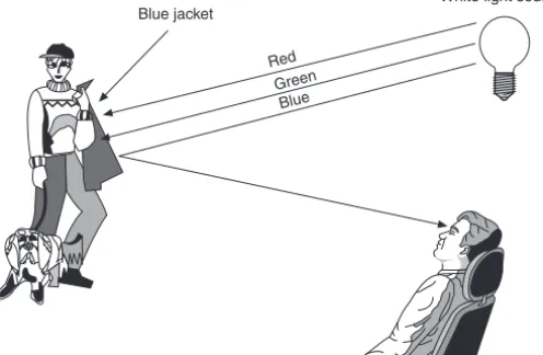
Light and the human eye 40
Measuring light 43
Light characteristics 45
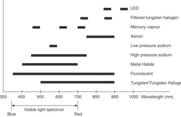
Artificial lighting 46
4 Lenses 52
Lens theory 52
Lens parameters 54
Zoom lenses 70
Electrical connections 72
Lens mounts 76
Filters 78
Lens adjustment 78
5 Fundamentals of television 83
The cathode ray tube 83
The colour CRT 87
Producing a raster 89
Picture resolution 92
Synchronization 95
The luminance signal 98
The chrominance signal 99
Television signals 102
Digital video signals 105
Video compression 108
MPEG-2 compression 110
Wavelet compression 113
6 The CCTV camera 115
Tube/CCD comparison 115
Charge coupled device 115
Deriving an interlaced raster 116
CCD chip operation 118
Colour imaging 123
Camera operation 126
White balance 130
Camera sensitivity 131
Camera resolution 132
Camera operating voltages 133
Specialized cameras 134
7 Monitors 139
Block diagram 139
Monochrome monitor 146
Monitor safety 147
Terminator switches 149
Resolution 151
Ergonomics 151
8 Recording equipment 154
Video recording principles 155
VHS (Video Home System) 159
Super VHS 161
Time-lapse recording 164
Time-lapse VCR features 167
VCR maintenance 170
Video head cleaning 172
DAT recorders 174
Type management and care 174
Digital video tape 175
Disk-based video recording 177
Recording capacity 177
Security of digital information 181
9 Camera switching and multiplexing 182
Sequential switching 182
Matrix switching 187
The quad splitter 191
Video multiplexers 193
Video motion detection (VMD) 199
10 Telemetry control 202
Hard wired control 203
Control data transmission 205
Pan/tilt (P/T) control 207
Receiver unit 209
Dome systems 210
Data communications 211
11 Ancillary equipment 216
Camera mountings 216
Towers and columns 221
Pan/tilt units 224
Monitor brackets 229
Power supplies 230
12 Commissioning and maintenance 234
Commissioning 234
Measuring resolution 234
System handover 238
Preventative maintenance 240
Corrective maintenance 241
Fault location 242
Oscilloscope default settings 244
Glossary of CCTV terms 246
Index 259
Preface
In the preface to the first edition I wrote that closed circuit television (CCTV) was a growth industry, and that the growth was very much a result of the impact of new technology. As I write this preface to the second edition of Closed Circuit Television, this situation has not changed. Technology has continued to advance, bringing with it the possibility of much clearer images even in conditions where a few years ago it would have been impossible to film. Add to this the advances in digital recording, high speed data transmission and biometric recognition and alarm systems, and we have the ability to design and install CCTV systems that just a few years ago were the stuff of science fiction.
However, like any high tech installation, these systems will only function correctly if they are properly specified, installed and maintained. Consequently a CCTV engineer needs to be conversant with modern electrical, electronics, digital and microprocessor principles, electrical installation practice, health and safety issues and telecommunications and broadband technology, in addition to having an in-depth knowledge of CCTV principles and technology.
This book has been written to provide the latter in the above list – a knowledge of CCTV principles and technology. Like the first edition, it uses the City & Guilds/SITO Knowledge of Security and Emergency Alarm Systems syllabus (course 1851) as its basis, making it suitable reading for trainees studying towards this qualification or for those who are working towards an NVQ level II or III in CCTV installation and maintenance. However, to cater for those who are already practising in the industry but who wish to further their technical knowledge and understanding, this second edition includes discussion of such topics as digital video signal compression, digital tape and hard disk recording, and CAT5 structured cabling.
This second edition includes two completely new chapters covering lighting and ancillary equipment. Furthermore, where the first edition was devoted primarily to the UK PAL television system, having noted that the book was being purchased in somewhat large numbers across the Atlantic in the USA, it was felt only right that this new edition should incorporate NTSC television standards.
It is my hope and wish that trainees and engineers alike will find this a useful handbook and aid towards their personal development.
Acknowledgements
I would personally wish to thank all of those who have helped in the production of this book by providing information and/or support. I should mention Andrew Holmes of Data Compliance Ltd, David Grant of ACT Meters, Gar Ning of NG Systems, Martin Kane, Simon Nash of Pelco UK Ltd and Simon Liddy and Steve Pilling of PAC International Ltd.
1 The CCTV industry
The term ‘closed circuit’ refers to the fact that the system is self-contained, the signals only being accessible by equipment within the system. This is in contrast to ‘broadcast television’, where the signals may be accessed by anyone with the correct receiving equipment.
The initial development of television took place during the 1930s, and a number of test transmissions were carried out in Europe and America. In the UK these were from the Crystal Palace transmitter in London. The outbreak of the Second World War brought an abrupt end to much of the television development, although interestingly transmissions continued to be made from occupied Paris using an experimental system operating from the Eiffel Tower; the German propaganda machine was very interested in this new form of media.
Ironically, the war was to give television the boost it needed in terms of technology development because in the UK it seemed like every scientist who knew anything about radio transmission and signals was pressed into the accelerated development programme for radar and radio. Following the war many of these men found themselves in great demand from companies eager to renew the development of television.
Early black and white pictures were of poor resolution, however the success of the medium meant that the money became available to develop new and better equipment, and to experiment with new ideas. At the same time the idea of using cameras and monitors as a means of monitoring an area began to take a hold. However, owing to the high cost of equipment, these early CCTV systems were restricted to specialized activity, and to organizations that had the money to invest in such security. These systems were of limited use because an operator had to be watching the screen constantly; there was no means of recording video images in the 1950s, and motion detection connected to some form of alarm was the stuff of James Bond (only even he did not arrive until the 1960s!).
Throughout the 1960s and 1970s CCTV technology progressed slowly, following in the footsteps of the broadcast industry which had the money to finance new developments. The main stumbling block lay in the camera technology which depended completely on vacuum tubes as a pick-up device. Tubes are large, require high voltages to operate, are generally useless in low light conditions (although special types were developed – for a price), and are expensive. Furthermore, an early colour camera required three of these tubes. For this reason throughout these years CCTV remained on the whole a low resolution, monochrome system which was very expensive.
2 Closed Circuit Television
businesses and organizations. Also, VHS had arrived. This had quite an impact on the industry because for the first time it was possible to record CCTV images on equipment that cost well below £1000. Prior to this, CCTV could be recorded on monochrome reel-to-reel machines, however these were expensive and were not exactly user-friendly.
From the mid 1980s onwards television technology advanced in quantum leaps. New developments such as the CMOS microchip and charge coupled device (CCD) chip brought about an increase in equipment capability and greatly improved picture quality, whilst at the same time equipment prices plummeted. Manufacturers such as Panasonic and Sony developed digital video recording machines, and although these were intended primarily for use in the broadcast industry (at £50000 for a basic model the CCTV industry was not in a hurry to include one with every installation!), they paved the way for digital video signal processing in lower resolution CCTV and domestic video products.
Up until recently, CCTV has had to rely on its big brother the broadcast industry to develop new technologies, and then wait for these technologies to be downgraded so that they become affordable to customers who cannot afford to pay £30000 per camera and £1000 per monitor. However, the technology explosion that we are currently seeing is changing this. PC technology is rapidly changing our traditional ideas of viewing and recording video and sound, and much of this hardware is inexpensive. Also, whereas in the early years the CCTV industry relied largely on the traditional broadcast and domestic television equipment manufacturers to design the equipment, there are now a number of established manufacturers that are dedicated to CCTV equipment design and production. These manufacturers are already taking both hardware and concepts from other electronics industries and integrating them to develop CCTV equipment that not only produces high quality pictures but is versatile, designed to allow easy system expansion, user-friendly, and can be controlled from anywhere on the planet without having to sacrifice one of its most valuable assets – which is that it is a closed circuit system.
The role of CCTV
So often CCTV is seen as a security tool. Well of course it is, however it also plays equally important roles in the areas of monitoring and control. For example, motorway camera systems are invaluable for monitoring the flow of traffic, enabling police, motoring organizations and local radio to be used to warn drivers of problems, and thus control situations. And in the case of a police chase, control room operators can assist the police in directing their resources. The same of course applies to town centre CCTV systems.
The CCTV industry 3
alarm bells among those who are mindful of George Orwell’s book Nineteen Eighty-Four. Indeed, in the wrong hands, or in the hands of the sort of police state depicted in that book, CCTV could be used for all manner of subversive activity. In fact the latest technology has gone beyond the predictions of Mr Orwell. Face recognition systems which generate an alarm as soon as it appears in a camera view have been developed, as have systems that track a person automatically once they have been detected. Other equipment which can see through a disguise by using parameters that make up a human, such as scull dimensions and relative positions of extreme features (nose, ears, etc.), or the way that a person walks, is likewise under development. At the time of writing all such systems are still somewhat experimental and are by no means perfected, however with the current rate of technological advancement we can only be a few years away from this equipment being installed as standard in systems in town centres, department stores, night clubs and anywhere else where the authorities would like early recognition of ‘undesirables’. To help control the use of CCTV in the UK the changes made to the Data Protection Act in 1998 meant that images from CCTV systems were now included. Unlike the earlier 1984 Act, this has serious implications for the owners of CCTV systems as it makes them legally responsible for the management, operation and control of the system and, perhaps more importantly, the recorded material or ‘data’ produced by their system. The Data Protection Act 1998 requires that all non-domestic CCTV systems are registered with the Information Commissioner. Clear signs must be erected in areas covered by CCTV warning people that they are being monitored and/or recorded. The signs must state the name of the ‘data controller’ of the system and have contact details. When registering a system, the data controller must state its specific uses and the length of time that material will be retained. Recorded material must be stored in a secure fashion and must not be passed into the public domain unless it is deemed to be in the public interest or in the interests of criminal investigations (i.e. the display of images on police-orientated programmes). On 2 October 1998 the Human Rights Act became effective in the UK. The emphasis on the rights to privacy (among other things) has strong implications for CCTV used by ‘public authorities’ as defined by the Act, and system designers and installers should take note of these implications. Cameras that are capable of targeting private dwellings or grounds (even if that is not their real intention) may be found to be in contravention of the rights of the people living there. As such, those people may take legal action to have the cameras disabled or removed – an expensive undertaking for the owner or, perhaps, the installing company who specified the camera system and/or locations.
In relation to CCTV, the intention of both the Data Protection and Human Rights Acts is to ensure that CCTV is itself properly managed, monitored and policed, thus protecting against it becoming a law unto itself in the future.
4 Closed Circuit Television
huge positive impact on the lives of people who live under its watchful eye. It has been proven time and again that both people and their possessions are more secure where CCTV is in operation, that people are much safer in crowded public places because the crowd can be better monitored and controlled, and possessions and premises are more secure because they can be watched 24 hours per day.
The CCTV industry
Despite what we have said about CCTV being used for operations other than security, it can never fully escape its potential for security applications because, whatever its intended use, if the police or any other public security organization suspect that vital evidence may have been captured on a system, they will inspect the recorded material. This applies all the way down to a member of the public who, whilst innocently using a camcorder, captures either an incident or something relating to an incident. For this reason it is perhaps not surprising to hear that the CCTV industry is largely regulated and monitored by the same people and organizations that monitor the security industry as a whole.
The British Security Industry Association (BSIA) Ltd is the only UK trade association for the security industry that requires its members to undergo independent inspection to ensure they meet relevant standards. The association has over 500 members and represents thirteen different sectors of the industry. There are 50 CCTV companies in membership, representing approximately 75% of the UK turnover for this sector. The BSIA’s primary role is to promote and encourage high standards of products and services throughout the industry for the benefit of customers. This includes working with its members to produce codes of practice, which regularly go on to become full British/European standards. The BSIA also lobbies government on legislation that may impact on the industry and actively liaises with other relevant organizations, for example the Office of the Information Commissioner (in relation to the Data Protection Act) and the Police Scientific Development Branch. The BSIA also provides an invaluable service in producing technical literature and training materials for its members and their customers.
The CCTV industry 5
has sufficient personnel, vehicles and equipment to meet maintenance requirements and breakdown response times.
In some cases the organization is expected to obtain BS EN ISO 9002 quality assurance (QA) accreditation within two years of becoming an approved installer. At the time of writing there is no specific requirement that engineers working for an approved installation company hold a National Vocational Qualification (NVQ) in security and emergency systems engineering, however this may well become the case in the future. Another significant body is the Security Industry Training Organization (SITO Ltd). SITO is responsible for the development of training standards for the security industry, and is recognized and approved by the DfES for this function. During recent years SITO has worked to develop NVQs as well as other awards for all sectors of the security industry, and in relation to CCTV engineering have developed awards to NVQ levels II and III. These awards are jointly accredited by SITO and City & Guilds.
City & Guilds are an established and recognized examinations body. With regard to the security industry, apart from awarding certificates to successful NVQ candidates, the City & Guilds appoint the external verifiers whose role it is to check that NVQ assessment centres, be these colleges, training organizations or installing companies, are carrying out the assessments to the recognized standards.
The City & Guilds also offer the Underpinning Knowledge test papers (course 1851) for the four disciplines relating to security and emergency system engineering; these being CCTV, intruder alarm, access control and fire alarm systems. These awards are intended to contribute towards the underpinning knowledge testing for the NVQ level III award, although a candidate may elect to sit these tests without pursuing an NVQ. It must be stressed, however, that the 1851 award is not an alternative qualification to an NVQ, and a person holding only the 1851 certificates would not be deemed to be qualified until they have proven their competence in security system engineering.
The Home Office department of the Police Scientific Development Branch (PSDB) play a most significant role in CCTV. For many years the CCTV industry had no set means of measuring the performance of its systems in terms of picture quality, resolution and the size of images as they appear on a monitor screen. This meant that in the absence of any benchmarks to work to, each surveyor or installer would simply do what they considered best. This situation was not only unsatisfactory for the industry, potential customers were in a position where they had no way of knowing what they could expect from a system and, once installed, had no real redress if they were unhappy, because there was nothing for them to measure the system performance against.
6 Closed Circuit Television
2 Signal transmission
A CCTV video signal contains a wide range of a.c. components with frequencies between 0–5.5MHz, in addition to a d.c. component, and problems occur when engineers consider a video signal in the same terms as a low voltage d.c. or low frequency mains supply. However, when you consider that domestic medium wave radio is transmitted around 1MHz, then it becomes clear that the 0–5.5MHz video signal is going to behave in a similar manner to radio signals.
In this chapter we shall examine the peculiar way in which radio frequency signals behave when they are passed along cables, and therefore explain the need for special cables when transmitting video signals.
CCTV signals
An electronically produced square wave signal is actually built up from a sinusoidal wave (known as the fundamental) and an infinite number of odd harmonics (odd multiples of the fundamental frequency). This basic idea is illustrated in Figure 2.1 where it can be seen that the addition of
Figure 2.1 Effect of the addition of odd harmonics to a sinusoidal waveshape
Fundamental
Third harmonic
Flatter top Steeper
sides
8 Closed Circuit Television
just one odd harmonic component changes the appearance of the fundamental sine wave, moving it towards a square shape.
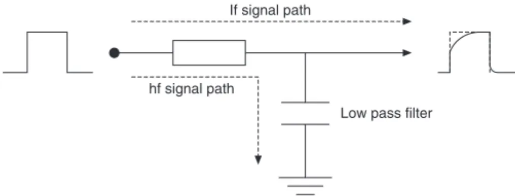
If we reverse this process, i.e. begin with a square wave and remove some of the harmonic components using filters, then the corners of the square wave become rounded, and the rise time becomes longer. This effect is illustrated in Figure 2.2.
Figure 2.2 Removal of high frequency harmonic components reduces the rise time and rounds the corners
If signal path
hf signal path
Low pass filter
In Chapter 5 we shall be looking at the make-up of the video signal (Figure 5.18), and we will see that it contains square wave components. It is the sharp rise times and right-angled corners in the video signal waveform which produce the high definition edges and high resolution areas of the picture. If for any reason the signal is subjected to a filtering action resulting in the loss of harmonics, the reproduced picture will be of poor resolution and may have a smeary appearance. Now one may wonder how a video signal could be ‘accidentally’ filtered, and yet it is actually quite possible because all cables contain elements of resistance, capacitance and inductance; the three most commonly used components in the construction of electronic filter circuits. When a signal is passed along a length of cable it is exposed to the effects of these R, C, L components. The actual effect the cable has on a signal is dependent on a number of factors, which include the type and construction of cable, the cable length, the way in which bends have been formed, the type and quality of connectors and the range of frequencies (bandwidth) contained within the signal. This means that, with respect to CCTV installations, it is important that correct cable types are used, that the correct connectors are used for a given cable type, that the cable is installed in the correct specified manner and that maximum run lengths are not exceeded without suitable means of compensation for signal loss.
Signal transmission 9
Co-axial cable
The behaviour of high frequency signals in a copper conductor is not the same as that of d.c. or low frequencies such as 50/60Hz mains or audio, and specially constructed cables are required to ensure constant impedance across a range of frequencies. Furthermore, radio frequency signals have a tendency to see every copper conductor as a potential receiving aerial, meaning that a conductor carrying an RF signal is prone to picking up stray RF from any number of sources, for example emissions from such things as electric motors, fluorescent lights, etc., or even legitimate radio transmissions. Co-axial cable is designed to meet the unique propagation requirements of radio frequency signals, offering constant impedance over a range of frequencies and some protection against unwanted noise pick-up.
There are many types of co-axial cable, all manifesting different figures for signal loss, impedance, screening capability and cost. The construction of a co-axial cable determines the characteristics for a particular cable type, the basic physical construction being illustrated in Figure 2.3.
Figure 2.3 Co-axial cable construction
Inner insulating sleeve
Copper core
Copper braid
Insulating outer sleeve
10 Closed Circuit Television
Integrity of the screen is maintained by ensuring that there are no breaks in the screen at any point along the cable length, and that all connectors are of the correct type for the cable and have been fitted correctly. We shall consider connectors later in this chapter, but the issue of breaks in the screen is one which we need to consider. Co-axial cable is more than a simple piece of wire, and only functions correctly when certain criteria have been met in relation to terminations and joints. Under no circumstances should a joint be made by simply twisting a pair of cores together and taping them up before twisting and taping the two screens. Although this might appear to be electrically correct, it breaks all the rules of RF theory and, among other things, exposes the inner core to RFI. All joins should be made using a correctly fitted connector (usually BNC) on each cable end, with a coupling piece inserted in between.
Where RFI is present in a video signal, it usually manifests itself as a faint, moving, patterning effect superimposed onto the picture. The size and speed of movement of the pattern depends on the frequency of the interfering signal.
The inner sleeve of the co-axial cable performs a much more important function than simply insulation between the two conductors; it forms a dielectric between the conductors which introduces a capacitive element into the cable. This cable capacitance works in conjunction with the natural d.c. resistance and inductance to produce a characteristic impedance (Zo)
for the cable. One of the factors which governs the value of a capacitor is the type of dielectric (insulator) used between the plates, and co-axial cables of differing impedances are produced by using different materials for the inner core. This is why not all co-axial cables are suitable for CCTV applications, and why a connector designed for one cable type will not fit onto certain other types; the cable diameter varies depending upon the dielectric. The equivalent circuit of a co-axial cable is shown in Figure 2.5.
Figure 2.4 RFI is contained by the copper screen, preventing it entering the signal processing circuits
Signal processing circuit boards Striplights RFI
Car ignition
Radio transmitters
Signal transmission 11
The characteristic impedance for a cable of infinite length can be found from the equation Zo = L C/ . However, this concept is somewhat theoretical as we do not have cables of infinite length. On the other hand, for a co-axial cable to function as a transmission line with minimum signal loss and reflection (we will look at this in a moment), the termination impedance at both ends must equal the calculated characteristic impedance for an infinite length. Thus, if the characteristic impedance, Zo, for a cable is quoted as being 75Ω, then the equipment at both ends of the cable must have a termination impedance of 75Ω.
If this is not the case a number of problems can occur. First of all signal loss may be apparent because of power losses in the transfer both to and from the cable. It can be shown that for maximum power transfer to occur between two electrical circuits, the output impedance of the first circuit must be equal to the input impedance of the second (Figure 2.6). If this is not the case, some power loss will occur. In our case the co-axial cable can be considered to be an electrical circuit, and this is why all equipment connected to the cable must have a matching impedance.
Figure 2.5 Equivalent circuit of a co-axial cable, also known as a transmission line
Unit A
Zout Zin
Unit B
Figure 2.6 Maximum power transfer only occurs when Zout in Unit A is equal
to Zin in Unit B. (Assume that the connecting cables have zero impedance)
12 Closed Circuit Television
sporadically, leaving the unsuspecting service engineer chasing from one end of the installation to the other looking for what appears to be a number of shifting faults; and perhaps for no other reason than because a careless installation engineer has made a Sellotape style cable connection in a roof space!
CCTV equipment is designed to have 75Ω input and output impedances. This means that 75Ω co-axial cable must always be used. Here again the installing engineer must be aware that not all co-axial cable has 75Ω impedance, and 50Ω and 300Ω versions are common. For example, cable type RG-59 is a common 75Ω co-axial cable used in CCTV installations. Cable type RG-58 looks very similar, but it is designed for different applications and has a characteristic impedance of 50Ω. A CCTV installation using this cable would never perform to its optimum capability, if indeed it were able to perform at all.
The subject of termination and termination switches will be discussed again in Chapter 7.
Up to now we have not taken into consideration the length of the co-axial cable. Over short distances the effects of C and R on the signal are small and can be ignored. However, as the cable length is increased these components have an effect on the signal which is similar to a voltage drop along a d.c. supply cable, the main difference being that the filtering action of the cable results in greater losses at the higher signal frequencies. Figure 2.7 illustrates a typical co-axial cable frequency response. Cable losses are usually quoted in terms of dB per 100m, at a given frequency. Manufacturers may quote figures for a range of frequencies, however those quoted for around 5MHz are the most significant to the CCTV engineer because, as seen from Figure 2.7, it is at the top end of the video signal frequency response where the most significant losses occur.
Every cable employed in CCTV signal transmission has a specified maximum length, beyond which optimum system performance will only
0 dB
–1
–2
–3
–4
Signal loss per 100 m
0 1 2 3 4 5 6
f MHz
Signal transmission 13
be maintained if additional equipment is installed. Typical specifications for the three most common co-axial cables employed in the CCTV industry are given in Table 2.1. The figures quoted for the maximum cable run length are those quoted in the BSIA Code Of Practice for Planning, Installation and Maintenance of CCTV Systems, October 1991, and some variance with these figures may be noted when comparing different manufacturers’ data, however the installer will do well to heed the guidelines laid down in the BSIA document.
Table 2.1
Cable Max run Impedance Loss/100m
type length at 5 MHz
URM-70 250m 75Ω 3.31dB
RG-59 350m 75Ω 2.25dB
RG-11 700m 75Ω 1.4dB
As a rule, monochrome signals tend to cope better with long cable runs than do colour signals. This is because a PAL colour signal contains a high frequency 4.43MHz colour subcarrier which is affected by the filtering action of the cable. However, even a monochrome signal contains hf components and, bearing in mind the effects of hf filtering on a square wave (Figure 2.2), will therefore suffer some loss of resolution where the cable run length is excessive.
14 Closed Circuit Television
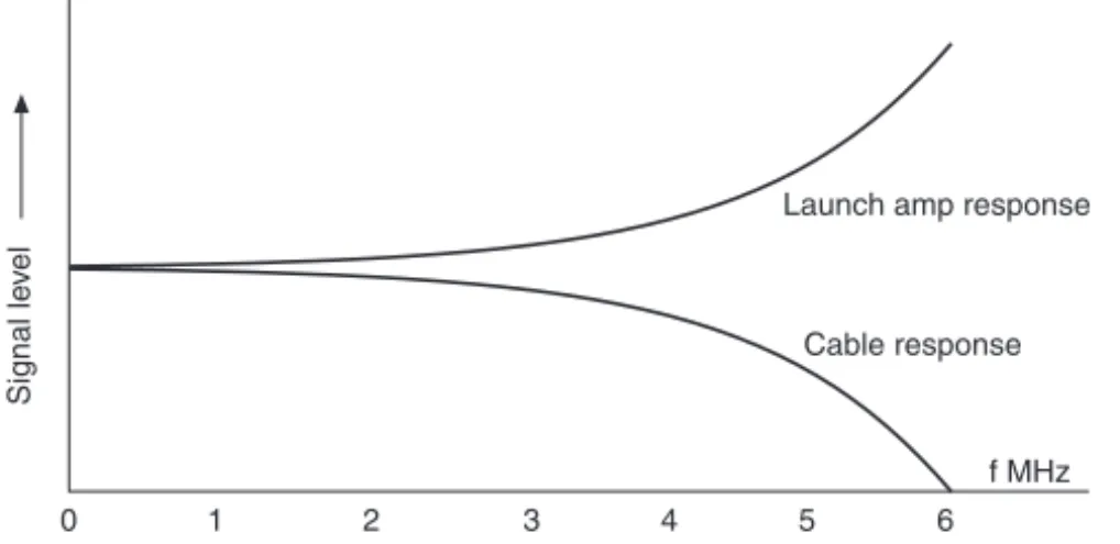
is designed to give extra lift to the higher frequencies where the greater losses occur.
Figure 2.8 A launch amplifier compensates for the filter action of the cable
The amplifier usually has an adjustment to allow the gain to be set to suit the length of cable; the longer the cable the higher the gain setting. The idea is to set the output voltage level such that, after losses, a uniform 1 Vpp signal appears at the other end. In some cases the gain control is calibrated in cable lengths, and it is therefore necessary to have an approximate idea of the length of the run. Do not simply turn the control until a ‘good, strong picture’ appears on the monitor. This practice can lead to problems in relation to vertical hold stability where switchers or multiplexers are involved, and possibly a loss of picture resolution.
A cable equalizer is a form of amplifier, however it is designed to be installed at the output end of the cable. The problem with this is that the unit is having to process the signal once the losses have been incurred, and in boosting the signal levels it will also boost the background noise level which will have arisen in the absence of a strong signal. The advantage of using a cable equalizer is that it can be installed in the control room, which can be a real plus in cases where the camera is inaccessible (Figure 2.9). If the installer has a choice of which to use, a launch amplifier is preferable as it lifts the signal before losses occur, thus maintaining a better signal to noise ratio.
It is possible to employ more than one amplifier in cases where very lengthy cable runs are required. The idea is that these are placed at even distances along the cable such that, just as the signal would begin to deteriorate, another amplifier lifts it once again. This principle is shown in Figure 2.10 where it can be seen that the total cable loss is –33.75dB, which is compensated for by the overall gain in the system of 36dB.
All this sounds well and good, however it takes a highly experienced engineer with the correct equipment to be able to adjust the gain and response of all of these units to a point where a perfect, uniform 1Vpp, 0–5.5MHz video signal is obtained at the other end without any increase in noise level. And remember, once noise has been introduced into the
Signal le
v
el
Launch amp response
Cable response
f MHz
Signal transmission 15
signal, it will simply be boosted along with the signal in each subsequent amplifier.
Still on the subject of losses, it should be noted that every BNC (or other type) connector introduces an element of signal attenuation and reflection, and it is good practice to keep the number of joins in a cable to a minimum.
All CCTV signal cable installation should comply with current codes of practice as laid down in BS 7671: Requirements for Electrical Installations, especially in relation to electrical segregation of low and high voltage cables. However, apart from the electrical safety issues surrounding segregation, installers should pay particular attention to the proximity of co-axial cables with mains power cables, in particular those carrying a high current, or supplying large numbers of fluorescent lights, heavy machinery, etc. Any current-carrying conductor produces an electromagnetic field around its length. Furthermore, high frequency spikes passing along a cable can produce large electric fields. Therefore it follows
Camera Launch amplifier
Camera
Cable equalizer
Monitor Monitor
Figure 2.9 Use of launch amplifiers and cable equalizers
Monitor Cable
equalizer –22.5 dB
1000m
–11.25dB 500m
Camera Launch amp 1 Launch amp 2 RG-59 cable loss = 2.25 dB/100m
16 Closed Circuit Television
that both of these energy fields must surround all mains supply cables, because they are carrying high frequency noise spikes in addition to the high current 50Hz mains supply. Where co-axial cables are laid parallel to mains cables, there is a good chance of the electromagnetic interference (EMI) penetrating the screen and superimposing a noise signal onto the video signal. Where this occurs, the displayed or recorded picture will suffer such effects as horizontal ripples rolling up or down, or random flashes when lights are switched or machinery operated.
Naturally the co-axial screen provides much protection against such noise ingression, however at best the screen will be no more than 95% effective, and some ‘budget’ cables may have a much lower figure. To prevent noise ingression it is good practice to avoid long, close-proximity, parallel co-axial/mains supply cable runs where ever possible, maintaining at least 30cm (12″) between cables. This may rule out using plastic segregated trunking because, although it offers electrical segregation, it does nothing to prevent the problems we have just outlined. Metal trunking provides screening against interference, and in cases where co-axial video cable must run through areas of high electrical noise, it is good practice to use steel trunking or conduit to minimize the chances of EMI compromising system performance.
Having looked at the construction of co-axial cable we know that the characteristic impedance depends, among other things, upon the capacitance of the cable, which is determined by the type and thickness of the inner insulating material. Therefore, should the inner sleeve become damaged by the cable being crushed, kinked or filled with water, the characteristic impedance will alter, opening the system up to the inherent problems of signal loss and reflected waves. Putting this another way, installers should take care not to damage the cable during installation, and should not lay cables in places where they may easily be damaged at a later time. BNC connectors are not waterproof and were never intended for external use. Therefore, where external connections are necessary, they should always be enclosed in a weatherproof housing. Once water enters a co-axial cable the capillary action may allow it to travel many metres along the cable, introducing all manner of undesirable picture effects, and very often these can be intermittent.
In order to prevent damage to the inner sleeve, co-axial cable should not have any severe bends. A rule of thumb is to ensure that the radius of all bends is no tighter than five times the diameter of the cable. For example, if the cable diameter is 6.5mm, the radius of a bend should be at least 32.5mm.
Ground loops
Signal transmission 17
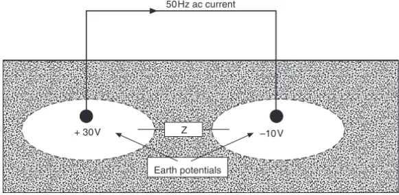
2.11 where a length of co-axial cable has a potential difference of +40V between its ends. It naturally follows that a current will flow through the low impedance co-axial screen which is by-passing the much higher impedance of the ground, which was the cause of the potential difference in the first place.
Differing ground potentials are very common, especially over long distances, and the problem can be further compounded when equipment at one end of a cable is connected to a different phase of the mains supply than that at the other end. The example in Figure 2.11 indicates a potential difference of 40V, however a difference of just 2–3V is sufficient to cause problems.
Co-axial screen earthed at both ends
–10V + 30V
Earth potentials
50Hz ac current
Z –10V
+ 30V
Earth potentials
Figure 2.11a A CCTV system where earth potentials differ
18 Closed Circuit Television
When a ground loop current flows along a co-axial cable screen, because the centre core is referenced to the screen, a 50Hz ripple is superimposed onto the video signal. This means that the brightness levels in the signal information are constantly moving at a rate of 50 Hz, and the effect on the monitor display is either a dark shadow or a ripple rolling vertically through the picture. This effect, often known as a hum bar, can also upset the synchronizing pulses, resulting in vertical picture roll.
It is possible to test for an earth potential problem during installation by taking an a.c. voltage measurement between the co-axial screen and the earth of the equipment to which it is to be connected. Under perfect earthing conditions, the reading should be 0V. In practice it is usual to obtain a reading of at least a few hundred millivolts, however in severe conditions potentials of 50V or even greater are possible. In such cases it is not safe to assume that the problem is simply caused by differences in earth potential as there might actually be a serious fault in the earth circuit of the electrical supply, and if the CCTV installer himself is not a qualified electrician, he should report the potential fault to the appropriate authorities, in writing, in order that a full inspection of the supply can be carried out.
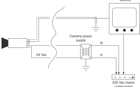
There are various ways of avoiding or overcoming the problem of ground loops in a CCTV system. Avoidance is always the best policy, but is not always practical. Remember that ground loops occur because the system has more than one earth point, and these are at differing potentials. Therefore if 12V d.c. or 24V a.c. cameras can be used, the only earth connection to the co-axial cable is at the control room end, and ground loops will not occur. This principle is illustrated in Figure 2.12. Other methods of avoidance are to employ twisted pair or fibre-optic cables,
Monitor
230 Vac mains outlet board P
N Camera power
supply
24 Vac
Signal transmission 19
which we shall be looking at later in this chapter. However, fibre-optic cables are more expensive to install, and besides, the problem may not be identified until after co-axial cables have already been installed.
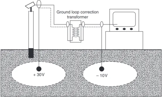
Ground loop correction equipment is available. There are two types: transformer and optical. Transformer types are usually contained in a sealed metal enclosure which acts as screening. In order to provide ideal coupling of the broadband video signal, the internal circuits may contain more than just a transformer. Nevertheless, the principle behind these units is to break the co-axial cable earth circuit but still provide video signal transmission without affecting the integrity of the cable screen. The basic circuit operation is shown in Figure 2.13. In practice a single unit may contain two transformers, allowing two separate video circuits to be corrected. The unit can be fixed at either end of the cable, although it is usually more convenient to locate it at the control room end.
Figure 2.13 Inclusion of a transformer breaks the 50Hz current path through the co-axial screen
Ground loop correction transformer
+ 30V – 10V
It is worth noting that not all correction transformers perform to the same standard when it comes to broadband video signal coupling, and sometimes a loss of resolution may be evident. Furthermore, where a transformer is not capable of coupling high frequencies, this can pose problems for certain types of telemetry control signal, resulting in a loss of telemetry to cameras which have a ground loop correction transformer included. As with any type of CCTV equipment, careful selection is important, and when you have found a product which performs satisfactorily, stay with it.
20 Closed Circuit Television
of individual inputs (typically 8 or 16) are available, and can be included with the control room equipment, acting as a buffer for each camera input. These are ideal for installations where it is anticipated at the planning stage that ground loops may pose a problem because it is known that cameras will either be connected across different phases of the mains supply, or will span a large geographical area. A multiple input ground loop corrector can be included in the initial quotation, thereby removing the problems of additional costs once the installation is underway.
Optical isolator
Figure 2.14 Principle of a single channel opto-isolator
Twisted pair cable
As the name implies, this cable comprises two cores which are wrapped around each other. The number of twists per metre varies depending upon the quality of the cable, however a minimum of ten turns per metre is recommended; the more turns there are the better the quality of the cable in terms of noise rejection.
This type of cable provides balanced signal transmission (as opposed to unbalanced, which is how co-axial cable works). As illustrated in Figure 2.15, in a balanced transmission system, because the two conductors are
EMI RFI
Signal transmission 21
twisted together, they are evenly exposed to any sources of electrical or magnetic interference present. Furthermore, the induced noise signals travel in the same direction along both conductors, whereas the video signal is travelling in opposite directions along each conductor (signal send and return).
The signal output from the BNC connector on the camera is fed immediately to a twisted pair transmitter which both isolates the twisted pair from earth, and places the video signal across the two wires. The transmitter also provides impedance matching between the 75Ω co-axial cable and the 100–150Ω twisted pair cable.
At the control room end a twisted pair receiver picks up the video signal and places it back onto a co-axial output for transmission to whatever equipment it is to be coupled. The receiver contains an operational amplifier (Op-amp) circuit which has two inputs: one wire of the pair is connected to each input. Because the noise signals are travelling in the same direction on both wires, they are effectively applied to both op-amp inputs where they are added in antiphase, thus cancelling them out. The video signal, on the other hand, is only present on the ‘send’ cable and is therefore only applied to one op-amp input, allowing it to be amplified in the normal way. This noise cancelling action is illustrated in Figure 2.16.
Figure 2.16 Noise at the inverting input is added to that at the non-inverting input, resulting in cancellation
Inverting input Op-amp +
Non-inverting input
–
In theory a twisted pair cable need not be screened; this type of cable is commonly referred to as unshielded twisted pair (UTP). However, in some instances a screen is recommended as it gives added protection against induced noise; this cable type is known as shielded twisted pair (STP). Note that because of the action of the twisted pair, mains hum introduced by ground loops is cancelled in the same manner as any other noise signal and thus the inclusion of the screen poses no problems in this area.
22 Closed Circuit Television
available which reduce both the installation cost and the number of separate boxes scattered behind the control console.
Co-axial links
Optional screen Twisted pair
transmitter Twisted pairreceiver
Figure 2.17 Twisted pair transmission arrangement
The primary advantage of using twisted pair video signal transmission in CCTV is the much longer cable runs possible owing to the much lower attenuation of the cable. Thus, 1000m for a colour signal transmission is easily possible, and manufacturers frequently quote figures in excess of 2000m for a monochrome signal.
There is no reason why twisted pair and axial cabling cannot exist in a CCTV installation, where shorter cable runs are made using co-axial cable and longer runs where signal loss and ground loops might prove problematic are made using twisted pair cable.
In some CCTV telemetry control systems a twisted pair cable is run alongside the co-axial video signal cable to carry the telemetry data to the pan/tilt/zoom (PTZ) units. Where the installer has chosen to use twisted pair for both video and telemetry signals, either two cables can be run, or alternatively a single four-core cable containing two separate twisted pairs is available.
Category 5 (Cat 5) cable
Category 5 cable is not specific to CCTV, rather it is a UTP data communications cable and cabling system that has been adopted by the industry for CCTV applications.
The ANSI/EIA (American National Standards Institute/Electronics Industries Association) have devised a number of standards that specify categories of twisted pair cable systems for commercial buildings. An outline of the six current categories can be seen in Table 2.2 and, at the time of writing, a seventh category is under consideration. The specifications for each category encompass not just the cable but the complete data transmission system including data transmission rates, system topologies, cable specifications, maximum cable and patch lead lengths, termination impedance and installation practice.
Signal transmission 23
commonly referred to) is currently the system which is of most interest to the CCTV industry because its high data rate makes it ideal for the transmission of video signals. During recent years Cat5 data systems have been installed into many buildings to support IT needs and in all modern buildings a structured data cable installation is as much a requirement as power and lighting cables. The communication used over the Cat5 system is the Ethernet 100BaseT where ‘100’ indicates a 100 Mbit per second (bps) data rate, ‘Base’ means that it is baseband signalling and ‘T’ indicates that it uses twisted pair cable. The earlier 10BaseT was capable of only 10Mbps and does not really have sufficient bandwidth to support the transmission of high definition digital video signals.
Connection to the Cat5 system is via a RJ-45 (Registered Jack) plug/ socket. The idea behind the system is that any Ethernet-compatible device may be connected to any socket and quickly set up to establish communications. This is commonly achieved by assigning an IP address to the device which, in the context of this book, would be a CCTV camera. The address may be dynamic, meaning that it is automatically requested by the camera when connected and the administrator computer automatically assigns an address, but more commonly the address is static. This means that an available address must be found and then manually assigned to each camera, a task that is normally performed with the assistance of the IT technician responsible for the computing and IT system.
The implications for CCTV (and indeed security alarm and access control systems) are enormous because, if cameras and pan/tilt units are made to be Ethernet/Internet Protocol (IP) ready, then installation is greatly simplified because there is no requirement for any cable installation. Furthermore, by using this interface, the system can be operated remotely from any point on the globe! Well, that is the theory. There are some practical considerations that should be made. First of all we must remember that digital video signals require a lot of bandwidth, even when compression is used (see Chapter 5), so there must be sufficient bandwidth in the system to handle the data. Then there is the issue of available bandwidth because, if the IT system is already working almost to capacity, then the addition of just one camera may well take it over the top, resulting in some devices on the network becoming excluded; and it may not be
Table 2.2
Category No. of twisted pairs No. of wires Max data rate (bps)
1 2 4 voice only – not
used for data
2 4 8 4 M
3 4 8 10 M
4 4 8 16 M
5 4 8 100 M
24 Closed Circuit Television
the camera that goes off-line, but perhaps other devices on the network such as printers, scanners, or even things like air conditioning if the building management system is also reliant on the Ethernet network. However, all too often it is seen as the task of the CCTV engineer to resolve such problems because, when all is said and done, everything worked until the cameras were brought on-line!
As a general rule, when considering using IP cameras the specifier or engineer must first ascertain the limitations of the existing Cat5 system. How much available bandwidth is there? How many cameras will be required? What is the bandwidth requirement of each camera? And finally, how well has the Cat 5/Ethernet system performed to date? Before connecting your CCTV system to an existing CAT5 network, it is prudent to find out if there has been a history of recurrent communications problems, otherwise you may find yourself attempting to resolve problems that have nothing at all to do with the CCTV installation. There are many systems that have been installed claiming to be Category 5 which, for one reason or another, do not comply with the ANSI specifications and thus fail to function correctly or reliably. The reasons for this may be that the cabling is incorrectly installed, equipment does not meet Category 5 standard, or IT protocols may be unsuitable for the application. In the latter case it is usual to confer with the system administrator to confirm system protocols.
On the other hand, where an IP CCTV camera is failing to function on a structured cable system which should be capable of supporting it, the engineer should check that an IP address has been given to the camera, that the socket is actually connected into the network, that the patch cable between the camera and RJ-45 socket is both correctly wired and is Cat5 compliant, and that the IP address being used by the camera has not already been assigned to another item of equipment. For this last check, the PING command is very helpful because a computer connected to the network will tell you immediately if the IP address is already in use. To execute the PING command you must first open the DOS screen, which is usually done from the START button on the bottom toolbar (assuming the operating system is Microsoft Windows™ 95 or later). Select the RUN option, type either CMD or COMMAND and the DOS screen should open with the flashing cursor at the CMD prompt. At this prompt, type PING followed by the IP address for the device you are looking for – in this case the camera in question. A typical PING command will look like:
PING 100.100.5.10
Signal transmission 25
device is found you will know that you have been given an address that is already in use and the system administrator will have to provide you with another. If no device is found, connect the camera and execute PING again. A device should now be found. If it is, then you know that at least the camera is on the network and that the reason for a lack of signal from it must lay somewhere else. If no device is found then, as previously stated, check the connections, cables, etc. and that the IP address is a valid one.
Another point to be aware of is that Cat3 and Cat5 cables physically look very similar; however Cat3 cable is only certified for 10Mbps (10BaseT) performance. For a UTP cable to meet Cat5 specifications, it should have a cable capacitance of not more than 17pF/ft (55pF/m) and a characteristic impedance of 100Ω. Also look out for excessive bending, stretching or crushing of the cable as all of these will alter the cable properties and can result in excessive data errors and subsequent system failure.
Where it is felt that an existing Cat5 network would be inadequate to support an IP CCTV system, the installer could consider having a dedicated Cat5 installed solely for the use of the CCTV system (and possibly other security systems such as intruder and access control). In these circumstances it once again becomes necessary to install cables whether they be co-axial, twisted pair or Cat5, but by employing Cat 5, the CCTV system will have all of the advantages of an IP addressable system. A word of warning; if you have never installed Category 5 cable before, it would be inadvisable to take on the responsibility for installing a system without having prior training or at least working through one of a number of distance learning structured cabling courses. Remember, a Category 5 system will only perform to its design specifications when certain rules (which are beyond the scope of this textbook) are adhered to.
Many manufacturers now have a range of cameras that have no composite video output, but simply an RJ-45 connector. Such cameras are ready to hook up to an Ethernet system and, when used with supporting IP ready controllers and switchers, greatly simplify the installation of powerful, yet versatile CCTV systems.
Ribbon cable
Also known as ‘Flat Twin’ cable, this has two parallel conductors and functions on the balanced transmission principle we have just been discussing. Because the conductors are not twisted it cannot be guaranteed that they will both be subjected to identical amounts of noise energy, although in practice over short distances this will usually be the case. A typical ribbon cable construction is shown in Figure 2.18.
26 Closed Circuit Television
Fibre-optic cable
Fibre-optic signal transmission was largely pioneered by the telecommunications industry, and for many years it remained very much within that industry. Perhaps this was because of the specialized skills and equipment required to install fibre-optic cables, particularly in relation to joining (splicing) and terminating. Or perhaps it was due to the relatively higher cost of the cable compared with co-axial or other copper transmission media. Whatever the reason, the CCTV industry was slow to pick up on what is by far the most effective method of sending CCTV signals over any distance.
Because the signal travelling through a fibre-optic cable is in the form of light, the medium is not prone to any of the problems associated with copper transmission systems such as RFI, EMI, lightning, etc. Yet fibre-optic transmission has a much wider bandwidth and much lower signal attenuation figures, which means that signals can be sent over far greater distances without the need for any line correction equipment. Fibre-optic cable also provides complete electrical isolation between equipment so there is never any chance of a ground loop, and from a security point of view it is almost impossible to tap into without it being obvious at the receiving end.
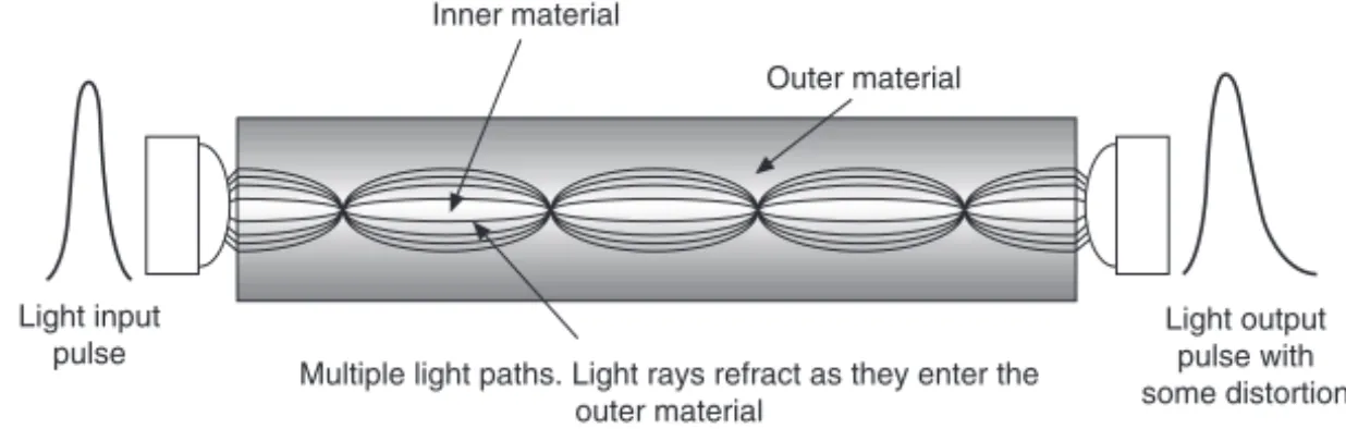
One of the greatest problems associated with signal transmission through optical cable is that of modal distortion which is caused by the light energy finding a number of different paths through the cable. Because the path lengths are not all the same, a single light pulse with a duration of, say, 1ns applied at the input arrives at the output over a period of around 2 ns. In other words the information becomes distorted. The longer the cable run, the more acute the problem.
The degree of modal distortion per unit length is determined by the
Signal transmission 27
construction of the fibre-optic material, and there are a number of cable types available, each having differing characteristics. In order to minimize modal distortion, specially engineered cable must be used, however the manufacturing of these cables is very expensive. For CCTV systems the cable runs are relatively short (compared with something like a transatlantic undersea telephone cable!), and therefore the effects of modal distortion are minimal and cheaper cable designs are adequate.
Three forms of fibre-optic transmission are illustrated in Figure 2.19. Mono mode cable is the most expensive of the three owing to its very small core diameter (typically 5µm) but it offers the greatest transmission distances with minimal distortion. Step index multimode cable employs
Light source
Inner material
Outer material Light pick-up
Light output pulse with minimal
distortion Outer protective sleeve
Light input pulse
Inner material
Outer material
Multiple light paths. Light rays refract as they enter the outer material
Light output pulse with some distortion Light input
pulse Light input
pulse high degree of distortionLight output pulse with
Figure 2.19a Mono mode cable. Light travels in a straight line through the inner material
Figure 2.19b Step index multimode cable. Refraction between two different materials results in multiple light paths
28 Closed Circuit Television
two different materials in the core, each having a different refractive index. This results in multiple light paths of differing path lengths which are added at the output to produce a resultant signal. This cable is relatively inexpensive, however it offers the greatest degree of signal distortion. Graded index multimode cable also employs two different core materials, however in this case they are diffused into each other, resulting in a multitude of refractive indexes which causes the light to effectively ‘bounce’ from side to side as it passes along the cable. Graded index (GI) cable offers much better distortion figures than step index cable and is much less expensive than mono mode cable, making it the prime choice for CCTV applications. For both step and graded index cables the core diameter is much larger than for mono mode cable (typically 50µm).
With this particular type of fibre-optic cable, runs can easily reach 2km and, depending on the frequency of the light source, may extend much further without the need of any signal booster equipment.
The light source may be either a light emitting diode (LED) or a laser diode. Of the two, the LED is far less expensive, however it has a much lower operating frequency. Having said this, an LED can respond at frequencies of up to 100 MHz which is more than adequate for CCTV applications. The frequency of light emitted by the LED/laser diode varies between devices, however some frequencies suffer less attenuation than others, therefore offering much longer transmission distances, a factor which manufacturers cannot afford to ignore. The video signal is applied to the light source which translates the variations in signal voltage into brightness variations.
The light pick-up is a photodiode which is a device that converts light levels into corresponding voltage levels. This forms part of a receiver unit containing the necessary electronic signal processing to produce a 1Vpp standard video signal on a 75Ω impedance co-axial output.
There are a number of ways of multiplexing CCTV analogue video signals so that more than one can be transmitted through a single fibre-optic cable. The actual multiplexing techniques are complex and beyond the scope of this textbook, however it is useful for the CCTV installer who is considering fibre-optic video transmission to be aware that these multiplexers are available. The alternative to using a multiplexer is to use multicore fibre-optic cables, although these may prove to be a more expensive option.
Fitting connectors and making terminations requires special tools and jigs, although the equipment itself makes the process very simple. However, because of the specialisms associated with fibre-optic cable installation, the majority of CCTV installers sub-contract this part of the installation out to companies who specialize in this type of work. However, as the advantages of fibre-optic become clear, this situation might change as the number of fibre-optic installations increase.
Signal transmission 29
the skin and break off, causing irritation and even infection which can be difficult to deal with medically. Furthermore, broken particles can be inhaled under certain conditions and could remain lodged in the lung indefinitely. Even for engineers who do not deal with fibre-optic cable directly, where their work is following fibre-optic installation, they should check that the area has been properly cleaned, and should avoid allowing their skin to come into direct contact with the floor or other surface areas where they suspect that fibres may still be present.
Infra-red beam
In essence this is a variation of fibre-optic signal transmission. An infra-red light source is modulated by a video signal, and the light is focused by an optical assembly onto a receiver unit which may be a kilometre or more distant. Both the transmitter and receiver must be able to ‘see’ each other in a straight line of sight.
As with fibre-optic, there are two types of light source: LED and laser diode. Comparing the two, the LED transmitter is far less expensive, and it produces a wide, diverging beam in the order of 10–20°. However, the diverging beam limits the range to, generally, a few hundred metres. Naturally the limited range can be a problem, however the wide beam makes for fairly simple system alignment, and the structures to which the transmitter and receiver units are mounted do not have to be completely stable. The laser diode transmitter, on the other hand, produces a very tight beam of light (around 0.2°) which can travel much greater distances. However, the tight beam requires very accurate alignment, and equipment really needs to be mounted onto solid structures such as buildings to avoid signal loss caused by movement. Also beware of the effects of direct sunlight which can cause movement of the metal mountings, throwing the light beam off target.
When locating these units it must be remembered that any break in the light path will result in immediate loss of signal, and although infra-red light can penetrate fog and rain to some extent, the range of the equipment will be reduced and severe weather conditions may result in a loss of signal. Therefore beware of operating these at their specified limits; always allow for some amount of signal loss. Also be aware of other changes which may occur, such as leaves appearing on trees during spring, trees that may grow after the equipment has been installed, structures which might be erected, etc.
30 Closed Circuit Television
Figure 2.20 A wide beam infra-red link across a main road
The equipment usually resembles a pair of small camera housings, and a good quality product will include many of the essential ‘extras’ which come with camera housings such as wash/wipe, heater, and in some cases an optional fan to cool the equipment during the summer, remembering that extreme heat could cause temporary misalignment of the optics.
Microwave link
The term ‘microwave’ refers to a band of frequencies in the radio spectrum which extends from 3GHz to 30GHz (G = Giga which is 109, or 1000000000).
These frequencies are above the domestic UHF television channel frequencies and incorporate many of the domestic satellite TV transmissions and mobile phone signals.
In order to prevent interference between signals, the air waves are regulated and no-one is permitted to operate a radio signal transmitter without proper authority, unless it is on one of the frequency bands that have been allocated for free, unlicensed use, and even then the equipment must comply with certain regulations regarding its transmission power and bandwidth. A typical example of one of these ‘free for all’ channels is the CB radio band. These restrictions mean that CCTV signal transmitting equipment must operate within certain bands, and must not exceed certain power output levels. In the UK, microwave CCTV equipment operates on frequencies located around either 3GHz or 10GHz.
IR beam
IR transmitter
Camera
Signal transmission 31
Directional (dish) aerials are normally used (Figure 2.21). There are two advantages in this: firstly the transmission range is greatly increased if the power is channelled in one direction, and secondly the signal is more secure against interception by someone operating receiving equipment tuned to the same frequency. However, dish aerials require careful alignment, as just a few degrees of error can result in a loss of signal. This also means that the dishes must be stable. Note that if the dish alignment is only approximate, the signal may produce a perfect
A dipole (rod) aerial allows the RF energy to spread in all directions.
A dish aerial directs the RF energy in one direction, increasing the transmission range.
32 Closed Circuit Television
picture in good weather conditions, however as soon as rain or snow settles on the dishes the signal attenuation causes the picture to degrade, with the familiar ‘sparklies’ appearing. The technology is identical to satellite TV, and this phenomenon is familiar to anyone who has a mis-aligned or incorrectly sized dish on their home!
Microwave energy does not penetrate solid objects, and thus there must be a clear line of sight between the transmitter and the receiver. This factor tends to limit the use of microwave to short range, unless it is possible to locate the equipment at both ends of the system on top of high structures. Alternatively the signal would propagate well across flat expanses, however there are not many of these in the UK!
In a CCTV application, the transmitter is located close to the camera, connected by a co-axial link. The receiver is located somewhere within line of sight, but in a place where the signal can be sent via cable to the control room, ideally as close to the control room as possible.
Two-way versions are available. These allow transmission of video in one direction, and transmission of telemetry in the other. The advantage of this can be seen, however the equipment cost somewhat restricts the use of this technology. Some transmitters also include a sound channel.
UHF RF transmission
In recent years a number of domestic DIY CCTV kits have become available, however many DIY householders are unhappy at having to run cables around their homes, and when you see the way some of these have been installed it is not difficult to understand why! Thus the proposition of a wireless CCTV system can be very appealing to the householder.
These wireless systems have been adapted from a technology that was originally developed for domestic TV and VCRs. The idea is to connect the composite video output from a VCR into a local UHF transmitter. Because UHF will penetrate solid objects to a limited degree, the signal can be picked up in every room in the house. However, it must be noted that in many cases the signal may be picked up by the neighbours. This same equipment has been adopted for local CCTV signal transmission, but it must be noted that the range is very poor, and there is no security of the signal whatsoever. On the other hand there are circumstances where a UHF video transmitter designed for domestic VCR use can prove to be a cost-effective solution to a difficult problem.
CCTV via the telephone network
Signal transmission 33
first appear impossible to achieve, however this was successfully done for many years with specially developed slow scan equipment.
The principle behind slow scan is to grab a single TV picture frame, digitize it, send it along the PSTN line in the form of a dual tone audible signal, and then decode this signal at the receiving end. The problem is the time that it takes to send the digital information for just one frame, which is in the order of 32 seconds, not including dialling time.
Developments in digital video signal compression brought about an increase in the transmission rate, and fast scan was born. There are a number of variations on this theme, however the principle is to remove unnecessary information, and one of the ways in which this is achieved is by only transmitting changes in picture information once the first frame has been sent. This is known as conditional refresh. The drawback with this is that the picture begins to break up (pixelate) when a lot of sudden movement occurs, such as when the camera is panning. This can be overcome by using other compression tools such as prediction, where picture elements that are seen to be moving in a certain direction are not transmitted, but instead a mathematical algorithm is used