Chapter 37
Interference of Light Waves
C H A P T E R O U T L I N E
37.1
Conditions for Interference
37.2
Young’s Double-Slit
Experiment
37.3
Intensity Distribution of the
Double-Slit Interference
Pattern
37.4
Phasor Addition of Waves
37.5
Change of Phase Due to
Reflection
37.6
Interference in Thin Films
37.7
The Michelson Interferometer
1176
▲
The colors in many of a hummingbird’s feathers are not due to pigment. The iridescence that makes the brilliant colors that often appear on the throat and belly is due to an1177
I
n the preceding chapter, we used light rays to examine what happens when lightpasses through a lens or reflects from a mirror. This discussion completed our study of
geometric optics. Here in Chapter 37 and in the next chapter, we are concerned with
wave opticsor physical optics, the study of interference, diffraction, and polarization of
light. These phenomena cannot be adequately explained with the ray optics used in Chapters 35 and 36. We now learn how treating light as waves rather than as rays leads to a satisfying description of such phenomena.
37.1
Conditions for Interference
In Chapter 18, we found that the superposition of two mechanical waves can be constructive or destructive. In constructive interference, the amplitude of the resultant wave at a given position or time is greater than that of either individual wave, whereas in destructive interference, the resultant amplitude is less than that of either individual wave. Light waves also interfere with each other. Fundamentally, all interference associ-ated with light waves arises when the electromagnetic fields that constitute the individ-ual waves combine.
If two lightbulbs are placed side by side, no interference effects are observed because the light waves from one bulb are emitted independently of those from the other bulb. The emissions from the two lightbulbs do not maintain a constant phase relationship with each other over time. Light waves from an ordinary source such as a lightbulb undergo random phase changes in time intervals less than a nanosecond. Therefore, the conditions for constructive interference, destructive interference, or some intermediate state are maintained only for such short time intervals. Because the eye cannot follow such rapid changes, no interference effects are observed. Such light sources are said to be incoherent.
In order to observe interference in light waves, the following conditions must be met:
• The sources must be coherent—that is, they must maintain a constant phase with respect to each other.
• The sources should be monochromatic—that is, of a single wavelength.
As an example, single-frequency sound waves emitted by two side-by-side loudspeak-ers driven by a single amplifier can interfere with each other because the two speakloudspeak-ers are coherent—that is, they respond to the amplifier in the same way at the same time.
37.2
Young’s Double-Slit Experiment
A common method for producing two coherent light sources is to use a monochro-matic source to illuminate a barrier containing two small openings (usually in the shape of slits). The light emerging from the two slits is coherent because a single
As with the hummingbird feathers shown in the opening photograph, the bright colors of peacock feathers are also due to interference. In both types of birds, structures in the feathers split and recombine visible light so that interference occurs for certain colors.
Conditions for interference
©
Kolar
source produces the original light beam and the two slits serve only to separate the original beam into two parts (which, after all, is what is done to the sound signal from the side-by-side loudspeakers at the end of the preceding section). Any random change in the light emitted by the source occurs in both beams at the same time, and as a result interference effects can be observed when the light from the two slits arrives at a viewing screen.
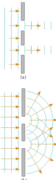
If the light traveled only in its original direction after passing through the slits, as shown in Figure 37.1a, the waves would not overlap and no interference pattern would be seen. Instead, as we have discussed in our treatment of Huygens’s principle (Section 35.6), the waves spread out from the slits as shown in Figure 37.1b. In other words, the light deviates from a straight-line path and enters the region that would otherwise be shadowed. As noted in Section 35.3, this divergence of light from its initial line of travel is called diffraction.
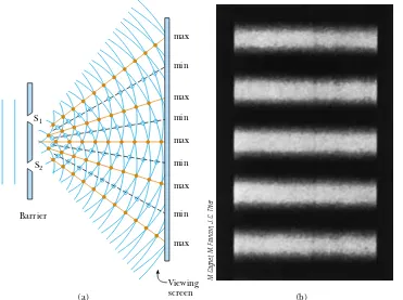
Interference in light waves from two sources was first demonstrated by Thomas Young in 1801. A schematic diagram of the apparatus that Young used is shown in Figure 37.2a. Plane light waves arrive at a barrier that contains two parallel slits S1and S2. These two slits serve as a pair of coherent light sources because waves emerging from them originate from the same wave front and therefore maintain a constant phase relationship. The light from S1 and S2 produces on a viewing screen a visible pattern of bright and dark parallel bands called fringes(Fig. 37.2b). When the light from S1and that from S2both arrive at a point on the screen such that constructive interference occurs at that location, a bright fringe appears. When the light from the two slits combines destructively at any location on the screen, a dark fringe results. Figure 37.3 is a photograph of an interference pattern produced by two coherent vibrating sources in a water tank.
Figure 37.4 shows some of the ways in which two waves can combine at the screen. In Figure 37.4a, the two waves, which leave the two slits in phase, strike the screen at the central point P. Because both waves travel the same distance, they arrive at P in phase. As a result, constructive interference occurs at this location, and a bright fringe is observed. In Figure 37.4b, the two waves also start in phase, but in this case the upper wave has to travel one wavelength farther than the lower Figure 37.1 (a) If light waves did
not spread out after passing through the slits, no interference would occur. (b) The light waves from the two slits overlap as they spread out, filling what we expect to be shadowed regions with light and producing interference fringes on a screen placed to the right of the slits.
At a beach in Tel Aviv, Israel, plane water waves pass through two openings in a breakwall. Notice the diffraction effect—the waves exit the openings with circular wave fronts, as in Figure 37.1b. Notice also how the beach has been shaped by the circular wave fronts.
Courtesy of Sabina Zigman/Benjamin Cardozo High School
(a)
(b)
▲
PITFALL PREVENTION
37.1
Interference Patterns
Are Not Standing
Waves
S E C T I O N 37. 2 • Young’s Double-Slit Experiment 1179
wave to reach point Q. Because the upper wave falls behind the lower one by exactly one wavelength, they still arrive in phase at Q, and so a second bright fringe appears at this location. At point R in Figure 37.4c, however, between points P and Q, the upper wave has fallen half a wavelength behind the lower wave. This means that a trough of the lower wave overlaps a crest of the upper wave; this gives rise to destructive interference at point R. For this reason, a dark fringe is observed at this location.
S1
S2
Barrier
Viewing screen
max
min
max
min
max
min
max
min
max
(a) (b)
Active Figure 37.2 (a) Schematic diagram of Young’s double-slit experiment. Slits S1 and S2behave as coherent sources of light waves that produce an interference pattern on the viewing screen (drawing not to scale). (b) An enlargement of the center of a fringe pattern formed on the viewing screen.
At the Active Figures link at http://www.pse6.com,you can adjust the slit separation and the wavelength of the light to see the effect on the interference pattern.
A
B
Figure 37.3 An interference pattern involving water waves is produced by two vibrating sources at the water’s surface. The pattern is analogous to that observed in Young’s double-slit experiment. Note the regions of constructive (A) and destructive (B) interference.
Richard Megna/Fundamental Photographs
(a)
Bright
fringe Dark
fringe
(b) (c)
Bright fringe S1
S2 S1
S2
Slits P P P
R
Q
Viewing screen
Q
S2 S1
Figure 37.4 (a) Constructive interference occurs at point Pwhen the waves combine. (b) Constructive interference also occurs at point Q. (c) Destructive interference occurs at Rwhen the two waves combine because the upper wave falls half a wavelength behind the lower wave. (All figures not to scale.)
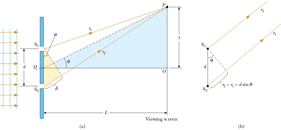
We can describe Young’s experiment quantitatively with the help of Figure 37.5. The viewing screen is located a perpendicular distance Lfrom the barrier containing two slits, S1and S2. These slits are separated by a distance d, and the source is monochromatic. To reach any arbitrary point Pin the upper half of the screen, a wave from the lower slit must travel farther than a wave from the upper slit by a distance dsin !. This distance is called the path difference"(lowercase Greek delta). If we assume that r1and r2are parallel, which is approximately true if Lis much greater than d, then "is given by
" #r2$r1#dsin! (37.1)
The value of " determines whether the two waves are in phase when they arrive at point P. If "is either zero or some integer multiple of the wavelength, then the two waves are in phase at point P and constructive interference results. Therefore, the condition for bright fringes, or constructive interference,at point Pis
(37.2)
The number mis called the order number.For constructive interference, the order number is the same as the number of wavelengths that represents the path difference between the waves from the two slits. The central bright fringe at! #0 is called the
zeroth-order maximum. The first maximum on either side, where m# %1, is called the
first-order maximum, and so forth.
When "is an odd multiple of &/2, the two waves arriving at point Pare 180° out of phase and give rise to destructive interference. Therefore, the condition for dark fringes, or destructive interference,at point Pis
(37.3)
It is useful to obtain expressions for the positions along the screen of the bright and dark fringes measured vertically from Oto P. In addition to our assumption that
L''d, we assume d''&. These can be valid assumptions because in practice Lis often on the order of 1 m, d a fraction of a millimeter, and & a fraction of a micrometer for visible light. Under these conditions, !is small; thus, we can use the small angle approximation sin!!tan!. Then, from triangle OPQ in Figure 37.5a,
d sin!dark#(m(12)&
(m#0, %1, %2, ) ) )) " #d sin!bright#m&
(m#0, %1, %2, ) ) ))
(b) r2–r1 = d sin
S1
S2
θ
d
r1
r2
(a) d
S1
S2 Q
L
Viewing screen
θ θ
P
O
δ
y r1
r2
θ
Figure 37.5 (a) Geometric construction for describing Young’s double-slit experiment (not to scale). (b) When we assume that r1is parallel to r2, the path difference between
the two rays is r2$r1#dsin !. For this approximation to be valid, it is essential that
L''d.
Path difference
Conditions for constructive interference
S E C T I O N 37. 2 • Young’s Double-Slit Experiment 1181 are likely to encounter some situ-ations in which this assumption is not valid. In those cases, the geo-metric construction will be more complicated, but the general approach outlined here will be is true to three-digit precision only for angles less than about 4°. If you are considering fringes 1.2 m. The distance between the two slits is 0.030 mm. The second-order bright fringe (m#2) is 4.5 cm from the center line.
(A) Determine the wavelength of the light.
Solution We can use Equation 37.5, with m#2, ybright# 4.5*10$2m, L#1.2 m, and d#3.0*10$5m:
which is in the green range of visible light. 560 nm
(B) Calculate the distance between adjacent bright fringes.
Solution From Equation 37.5 and the results of part (A),
Example 37.1 Measuring the Wavelength of a Light Source Interactive
we see that
Using Equations 37.3 and 37.4, we find that the dark fringes are located at
(37.6)
As we demonstrate in Example 37.1, Young’s double-slit experiment provides a
method for measuring the wavelength of light. In fact, Young used this technique to do just that. Additionally, his experiment gave the wave model of light a great deal of cred-ibility. It was inconceivable that particles of light coming through the slits could cancel each other in a way that would explain the dark fringes.
ydark# &L barrier and the viewing screen of Figure 37.5a, the smoke would show (a) no evidence of interference between the barrier and the screen (b) evidence of interference every-where between the barrier and the screen.
Quick Quiz 37.2
In a two-slit interference pattern projected on a screen, the fringes are equally spaced on the screen (a) everywhere (b) only for large angles (c) only for small angles.Quick Quiz 37.3
Which of the following will cause the fringes in a two-slit interference pattern to move farther apart? (a) decreasing the wavelength of the light (b) decreasing the screen distance L(c) decreasing the slit spacing d(d) immersing the entire apparatus in water.A light source emits visible light of two wavelengths: & # 430 nm and &+ #510 nm. The source is used in a double-slit interference experiment in which L#1.50 m and d#0.025 0 mm. Find the separation distance between the third-order bright fringes.
Solution Using Equation 37.5, with m#3, we find that the fringe positions corresponding to these two wavelengths are
Hence, the separation distance between the two fringes is
,y#9.18*10$2m$7.74*10$2m
What If? What if we examine the entire interference pattern due to the two wavelengths and look for overlapping fringes? Are there any locations on the screen where the bright fringes from the two wavelengths overlap exactly?
Answer We could find such a location by setting the location of any bright fringe due to &equal to one due to &+,
1.40 cm the 510-nm light. However, if we use Equation 37.5 to find the value of yfor these fringes, we find
This value of y is comparable to L, so that the small-angle approximation used in Equation 37.4 is notvalid. This suggests that we should not expect Equation 37.5 to give us the correct result. If you use the exact relationship y#Ltan!, you can show that the bright fringes do indeed overlap when the same condition, m+/m#&/&+, is met (see Problem 44). Thus, the 51st fringe of the 430-nm light does overlap with the 43rd fringe of the 510-nm light, but not at the location of 1.32 m. You are asked to find the correct location as part Example 37.2 Separating Double-Slit Fringes of Two Wavelengths
37.3
Intensity Distribution of the Double-Slit
Interference Pattern
Note that the edges of the bright fringes in Figure 37.2b are not sharp—there is a
gradual change from bright to dark. So far we have discussed the locations of only the centers of the bright and dark fringes on a distant screen. Let us now direct our attention to the intensity of the light at other points between the positions of maximum constructive and destructive interference. In other words, we now calculate the distribution of light intensity associated with the double-slit interfer-ence pattern.
Again, suppose that the two slits represent coherent sources of sinusoidal waves
such that the two waves from the slits have the same angular frequency - and a
constant phase difference .. The total magnitude of the electric field at point Pon the
screen in Figure 37.6 is the superposition of the two waves. Assuming that the two
waves have the same amplitude E0, we can write the magnitude of the electric field at
point Pdue to each wave separately as
E1#E0sin-t and E2#E0sin(-t(.) (37.7)
Although the waves are in phase at the slits, their phase difference.at P depends on the
path difference " #r2$r1#dsin!. A path difference of & (for constructive
interfer-ence) corresponds to a phase difference of 2/rad. A path difference of "is the same
S E C T I O N 37. 3 • Intensity Distribution of the Double-Slit Interference Pattern 1183
with the ratio
which gives us
(37.8)
This equation tells us precisely how the phase difference .depends on the angle !in
Figure 37.5.
Using the superposition principle and Equation 37.7, we can obtain the magnitude
of the resultant electric field at point P:
EP#E1(E2#E0[sin-t(sin(-t(.)] (37.9)
To simplify this expression, we use the trigonometric identity
Taking A#-t(.and B#-t, we can write Equation 37.9 in the form
(37.10)
This result indicates that the electric field at point Phas the same frequency -as the
light at the slits, but that the amplitude of the field is multiplied by the factor
2 cos(./2). To check the consistency of this result, note that if . #0, 2/, 4/, . . .,
then the magnitude of the electric field at point Pis 2E0, corresponding to the
condi-tion for maximum constructive interference. These values of . are consistent with
Equation 37.2 for constructive interference. Likewise, if . # /, 3/, 5/, . . ., then the
magnitude of the electric field at point Pis zero; this is consistent with Equation 37.3
for total destructive interference.
Finally, to obtain an expression for the light intensity at point P, recall from Section
34.3 that the intensity of a wave is proportional to the square of the resultant electric field
magnitude at that point(Eq. 34.21). Using Equation 37.10, we can therefore express the
light intensity at point Pas
Most light-detecting instruments measure averaged light intensity, and the
time-averaged value of sin2(-t(./2) over one cycle is . (See Figure 33.5.) Therefore, we
can write the average light intensity at point Pas
(37.11)
where Imaxis the maximum intensity on the screen and the expression represents the
time average. Substituting the value for .given by Equation 37.8 into this expression,
we find that
(37.12)
Alternatively, because sin!!y/L for small values of ! in Figure 37.5, we can write
Equation 37.12 in the form
(37.13)
I!Imax cos2
"
/d&L y
#
I#Imax cos2
"
/d sin!&
#
I#Imax cos2
"
.
2
#
1 2
I0EP2#4E02 cos2
"
.
2
#
sin2
"
-t( .2
#
EP#2E0 cos
"
.2
#
sin"
-t(.
2
#
sin A(sin B#2 sin
"
A(B2
#
cos"
A$B
2
#
. # 2/ & " #
2/
& d sin ! "
& # .
2/
Constructive interference, which produces light intensity maxima, occurs when the
quantity /dy/&Lis an integral multiple of /, corresponding to y#(&L/d)m. This is
consistent with Equation 37.5.
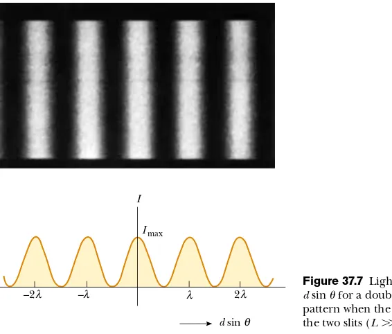
A plot of light intensity versus dsin! is given in Figure 37.7. The interference
pattern consists of equally spaced fringes of equal intensity. Remember, however, that
this result is valid only if the slit-to-screen distance L is much greater than the slit
separation, and only for small values of !.
Quick Quiz 37.4
At dark areas in an interference pattern, the light waves have canceled. Thus, there is zero intensity at these regions and, therefore, no energy is arriving. Consequently, when light waves interfere and form an interference pattern, (a) energy conservation is violated because energy disappears in the dark areas (b) energy transferred by the light is transformed to another type of energy in the dark areas (c) the total energy leaving the slits is distributed among light and dark areas and energy is conserved.I
–2 –λ λ 2
Imax
d sinθ λ
λ Figure 37.7dsin !for a double-slit interferenceLight intensity versus pattern when the screen is far from the two slits (L''d).
M. Cagnet, M. Francon, J.C. Thierr
37.4
Phasor Addition of Waves
In the preceding section, we combined two waves algebraically to obtain the resultant wave amplitude at some point on a screen. Unfortunately, this analytical procedure becomes cumbersome when we must add several wave amplitudes. Because we shall eventually be interested in combining a large number of waves, we now describe a graphical procedure for this purpose.
Let us again consider a sinusoidal wave whose electric field component is given
by
E1#E0sin-t
where E0is the wave amplitude and -is the angular frequency. We used phasors in
S E C T I O N 37. 4 • Phasor Addition of Waves 1185
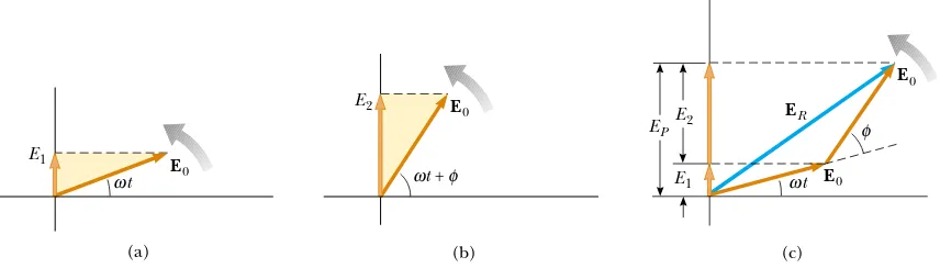
in discussing wave interference. The sinusoidal wave we are discussing can be
repre-sented graphically by a phasor of magnitude E0rotating about the origin
counterclock-wise with an angular frequency -, as in Figure 37.8a. Note that the phasor makes an
angle -t with the horizontal axis. The projection of the phasor on the vertical axis
represents E1, the magnitude of the wave disturbance at some time t. Hence, as the
phasor rotates in a circle about the origin, the projection E1oscillates along the
verti-cal axis.
Now consider a second sinusoidal wave whose electric field component is given
by
E2#E0sin(-t(.)
This wave has the same amplitude and frequency as E1, but its phase is . with
respect to E1. The phasor representing E2is shown in Figure 37.8b. We can obtain
the resultant wave, which is the sum of E1 and E2, graphically by redrawing the
phasors as shown in Figure 37.8c, in which the tail of the second phasor is placed
at the tip of the first. As with vector addition, the resultant phasor ER runs from
the tail of the first phasor to the tip of the second. Furthermore, ER rotates along
with the two individual phasors at the same angular frequency -. The projection
of ER along the vertical axis equals the sum of the projections of the two other
phasors: EP#E1(E2.
It is convenient to construct the phasors at t#0 as in Figure 37.9. From the
geom-etry of one of the right triangles, we see that
which gives
ER#2E0cos1
Because the sum of the two opposite interior angles equals the exterior angle ., we see
that 1 # ./2; thus,
Hence, the projection of the phasor ERalong the vertical axis at any time tis
This is consistent with the result obtained algebraically, Equation 37.10. The resultant
phasor has an amplitude 2E0cos(./2) and makes an angle ./2 with the first phasor.
EP#ER sin
"
-t( .2
#
#2E0 cos(./2) sin"
-t(.
2
#
ER#2E0 cos
"
.2
#
cos 1 # ER/2
E0
Figure 37.8 (a) Phasor diagram for the wave disturbance E1#E0sin -t. The phasor
is a vector of length E0rotating counterclockwise. (b) Phasor diagram for the wave
E2#E0sin(-t(.). (c) The phasor ERrepresents the combination of the waves in part (a) and (b).
Figure 37.9 A reconstruction of the resultant phasor ER. From the geometry, note that 1#./2.
E2 E0
(b) ωt + φ
ω φ E1 ωt E0
φ
(c) EP
E0
ER E2
E1
(a) E0
t
ω
E0
φ
E0
ER α
Furthermore, the average light intensity at point P, which varies as EP2, is proportional
to cos2(./2), as described in Equation 37.11.
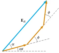
We can now describe how to obtain the resultant of several waves that have the same frequency:
• Represent the waves by phasors, as shown in Figure 37.10, remembering to
maintain the proper phase relationship between one phasor and the next.
• The resultant phasor ER is the vector sum of the individual phasors. At each
instant, the projection of ERalong the vertical axis represents the time variation of
the resultant wave. The phase angle 1of the resultant wave is the angle between ER
and the first phasor. From Figure 37.10, drawn for four phasors, we see that the
resultant wave is given by the expression EP#ERsin(-t(1).
Phasor Diagrams for Two Coherent Sources
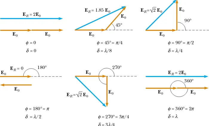
As an example of the phasor method, consider the interference pattern produced
These results are in complete agreement with the analytical procedure described in the preceding section.
Three-Slit Interference Pattern
Using phasor diagrams, let us analyze the interference pattern caused by three equally
spaced slits. We can express the electric field components at a point Pon the screen
caused by waves from the individual slits as
Figure 37.10 The phasor ERis the resultant of four phasors of equal amplitude E0. The phase of ERwith respect to the first phasor is 1. The projection EPon the vertical axis represents the combination of the at the Active Figures link at http://www.pse6.com and see the resultant phasor.
S E C T I O N 37. 4 • Phasor Addition of Waves 1187
E1#E0sin-t E2#E0sin(-t(.) E3#E0sin(-t(2.)
where . is the phase difference between waves from adjacent slits. We can obtain
the resultant magnitude of the electric field at point P from the phasor diagram in
Figure 37.12.
The phasor diagrams for various values of .are shown in Figure 37.13. Note that
the resultant magnitude of the electric field at Phas a maximum value of 3E0, a
condi-tion that occurs when . #0, %2/,%4/, . . . . These points are called primary
max-ima.Such primary maxima occur whenever the three phasors are aligned as shown in
Figure 37.13a. We also find secondary maxima of amplitude E0occurring between the
primary maxima at points where . # % /,%3/, . . . . For these points, the wave
from one slit exactly cancels that from another slit (Fig. 37.13d). This means that only light from the third slit contributes to the resultant, which consequently has a total
amplitude of E0. Total destructive interference occurs whenever the three phasors
form a closed triangle, as shown in Figure 37.13c. These points where ER#0
correspond to . # %2//3, %4//3, . . . . You should be able to construct other
phasor diagrams for values of .greater than/.
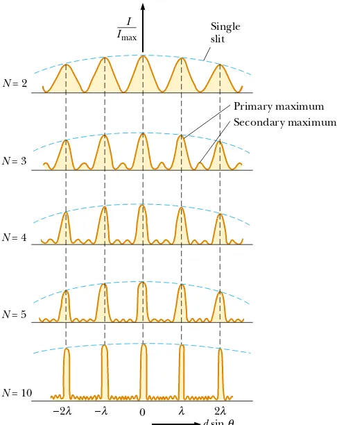
Figure 37.14 shows multiple-slit interference patterns for a number of confi
g-urations. For three slits, note that the primary maxima are nine times more intense than the secondary maxima as measured by the height of the curve. This is
because the intensity varies as ER2. For Nslits, the intensity of the primary maxima is
N2times greater than that due to a single slit. As the number of slits increases, the
primary maxima increase in intensity and become narrower, while the secondary maxima decrease in intensity relative to the primary maxima. Figure 37.14 also shows that as the number of slits increases, the number of secondary maxima also increases.
In fact, the number of secondary maxima is always N$2 where Nis the number of
slits. In Section 38.4 (next chapter), we shall investigate the pattern for a very large
number of slits in a device called a diffraction grating.
Active Figure 37.13 Phasor diagrams for three equally spaced slits at various values of .. Note from (a) that there are primary maxima of amplitude 3E0and from (d) that
there are secondary maxima of amplitude E0.
Choose any phase angle at the Active Figures link at http://www.pse6.com and see the resultant phasor.
180°
= 0 = 0
(a) (d)
120°
120°
60°
60°
ER = E0
ER = 0 ER = 2E0
ER ER = 3E0
E0 E0 E0
(b) (c)
φ δ
= 60°= /3 = /6
φ π
λ δ
= 120°= 2 /3 = /3
φ π
λ δ
= 180°= = /2
φ π
λ δ
Figure 37.12 Phasor diagram for three equally spaced slits.
φ
φ α
t ER
ω
37.5
Change of Phase Due to Reflection
Young’s method for producing two coherent light sources involves illuminating a pair of
slits with a single source. Another simple, yet ingenious, arrangement for producing an
interference pattern with a single light source is known as Lloyd’s mirror1(Fig. 37.15). A
point light source is placed at point S close to a mirror, and a viewing screen is positioned
some distance away and perpendicular to the mirror. Light waves can reach point Pon
the screen either directly from S to Por by the path involving reflection from the mirror.
The reflected ray can be treated as a ray originating from a virtual source at point S+. As a
result, we can think of this arrangement as a double-slit source with the distance between
points S and S+comparable to length din Figure 37.5. Hence, at observation points far
from the source (L''d) we expect waves from points S and S+to form an interference
pattern just like the one we see from two real coherent sources. An interference pattern is indeed observed. However, the positions of the dark and bright fringes are reversed
relative to the pattern created by two real coherent sources (Young’s experiment). This
can only occur if the coherent sources at points S and S+differ in phase by 180°.
To illustrate this further, consider point P+, the point where the mirror intersects
the screen. This point is equidistant from points S and S+. If path difference alone were
responsible for the phase difference, we would see a bright fringe at point P+(because
the path difference is zero for this point), corresponding to the central bright fringe of
Figure 37.14 Multiple-slit interference patterns. As N, the number of slits, is increased, the primary maxima (the tallest peaks in each graph) become narrower but remain fixed in position and the number of secondary maxima increases. For any value of N, the decrease in intensity in maxima to the left and right of the central maximum, indicated by the blue dashed arcs, is due to diffraction patternsfrom the individual slits, which are discussed in Chapter 38.
Figure 37.15 Lloyd’s mirror. An interference pattern is produced at point Pon the screen as a result of the combination of the direct ray (blue) and the reflected ray (brown). The reflected ray undergoes a phase change of 180°.
Single slit
N = 2
N = 3
N = 4
N = 5
N = 10
0 – 2λ
– λ λ λ 2λλ
Primary maximum Secondary maximum I
Imax
d sin θθ
S′ S Real source
Viewing screen
Mirror
P
P′
Virtual source
1 Developed in 1834 by Humphrey Lloyd (1800–1881), Professor of Natural and Experimental
S E C T I O N 37. 6 • Interference in Thin Films 1189
the two-slit interference pattern. Instead, we observe a dark fringe at point P+. From
this, we conclude that a 180°phase change must be produced by reflection from the
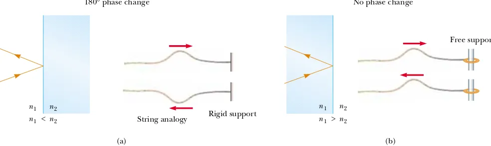
mirror. In general, an electromagnetic wave undergoes a phase change of 180°
upon reflection from a medium that has a higher index of refraction than the one in which the wave is traveling.
It is useful to draw an analogy between reflected light waves and the reflections of
a transverse wave pulse on a stretched string (Section 16.4). The reflected pulse on a
string undergoes a phase change of 180° when reflected from the boundary of
a denser medium, but no phase change occurs when the pulse is reflected from the
boundary of a less dense medium. Similarly, an electromagnetic wave undergoes a 180°
phase change when reflected from a boundary leading to an optically denser medium
(defined as a medium with a higher index of refraction), but no phase change occurs
when the wave is reflected from a boundary leading to a less dense medium. These
rules, summarized in Figure 37.16, can be deduced from Maxwell’s equations, but the
treatment is beyond the scope of this text.
37.6
Interference in Thin Films
Interference effects are commonly observed in thin films, such as thin layers of oil on
water or the thin surface of a soap bubble. The varied colors observed when white light
is incident on such films result from the interference of waves reflected from the two
surfaces of the film.
Consider a film of uniform thickness tand index of refraction n, as shown in Figure
37.17. Let us assume that the light rays traveling in air are nearly normal to the two
surfaces of the film. To determine whether the reflected rays interfere constructively or
destructively, we first note the following facts:
• A wave traveling from a medium of index of refraction n1 toward a medium of
index of refraction n2 undergoes a 180° phase change upon reflection when
n2'n1and undergoes no phase change if n22n1.
• The wavelength of light &nin a medium whose index of refraction is n(see Section
35.5) is
(37.14)
where &is the wavelength of the light in free space.
&n# & n
Rigid support String analogy
180° phase change
n1
n1
n2
n2 <
(a)
Free support No phase change
n1 n1
n2 n2
>
(b) Figure 37.16 (a) For n12n2, a light ray traveling in medium 1 when reflected from
the surface of medium 2 undergoes a 180°phase change. The same thing happens with a reflected pulse traveling along a string fixed at one end. (b) For n1'n2, a light ray
traveling in medium 1 undergoes no phase change when reflected from the surface of medium 2. The same is true of a reflected wave pulse on a string whose supported end is free to move.
No phase change
Air
180° phase change
1 2
A
t Film
Air
B
3 4
Let us apply these rules to the film of Figure 37.17, where nfilm'nair. Reflected
ray 1, which is reflected from the upper surface (A), undergoes a phase change of 180°
with respect to the incident wave. Reflected ray 2, which is reflected from the lower
film surface (B), undergoes no phase change because it is reflected from a medium
(air) that has a lower index of refraction. Therefore, ray 1 is 180°out of phase with ray
2, which is equivalent to a path difference of &n/2. However, we must also consider that
ray 2 travels an extra distance 2tbefore the waves recombine in the air above surface A.
(Remember that we are considering light rays that are close to normal to the surface.
If the rays are not close to normal, the path difference is larger than 2t.) If 2t#&n/2,
then rays 1 and 2 recombine in phase, and the result is constructive interference. In
general, the condition for constructiveinterference in thin films is2
(37.15)
This condition takes into account two factors: (1) the difference in path length for the
two rays (the term m&n) and (2) the 180° phase change upon reflection (the term
&n/2). Because &n#&/n, we can write Equation 37.15 as
(37.16)
If the extra distance 2ttraveled by ray 2 corresponds to a multiple of &n, then the
two waves combine out of phase, and the result is destructive interference. The general
equation for destructiveinterference in thin films is
(37.17)
The foregoing conditions for constructive and destructive interference are valid
when the medium above the top surface of the film is the same as the medium below
the bottom surface or, if there are different media above and below the film, the index
of refraction of both is less than n. If the film is placed between two different media,
one with n2nfilm and the other with n'nfilm, then the conditions for constructive
and destructive interference are reversed. In this case, either there is a phase change
of 180°for both ray 1 reflecting from surface Aand ray 2 reflecting from surface B, or
there is no phase change for either ray; hence, the net change in relative phase due to
the reflections is zero.
Rays 3 and 4 in Figure 37.17 lead to interference effects in the light transmitted
through the thin film. The analysis of these effects is similar to that of the reflected
light. You are asked to explore the transmitted light in Problems 31, 36, and 37. 2nt#m&
(m#0, 1, 2, ) ) ))
2nt#(m(12)&
(m#0, 1, 2, ) ) )) 2t#(m(12)&n
(m#0, 1, 2, ) ) ))
Conditions for destructive interference in thin films Conditions for constructive interference in thin films
2 The full interference effect in a thin film requires an analysis of an infinite number of
reflections back and forth between the top and bottom surfaces of the film. We focus here only on a single reflection from the bottom of the film, which provides the largest contribution to the interference effect.
Quick Quiz 37.6
In a laboratory accident, you spill two liquids onto water, neither of which mixes with the water. They both form thin films on the water surface. When the films become very thin as they spread, you observe that one film becomes bright and the other dark in reflected light. The film that is dark (a) has an index of refraction higher than that of water (b) has an index of refraction lower than that of water (c) has an index of refraction equal to that of water (d) has an index of refrac-tion lower than that of the bright film.Quick Quiz 37.7
One microscope slide is placed on top of another with their left edges in contact and a human hair under the right edge of the upper slide. As a result, a wedge of air exists between the slides. An interference pattern results when monochromatic light is incident on the wedge. At the left edges of the slides, there is (a) a dark fringe (b) a bright fringe (c) impossible to determine.▲
PITFALL PREVENTION
37.4
Be Careful with Thin
Films
Be sure to include both effects—
path length and phase change—
when analyzing an interference pattern resulting from a thin
film. The possible phase change is a new feature that we did not need to consider for double-slit interference. Also think carefully about the material on either side of the film. You may have situa-tions in which there is a 180°
S E C T I O N 37. 6 • Interference in Thin Films 1191
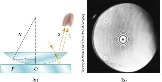
Figure 37.18 (a) The combination of rays reflected from the flat plate and the curved lens surface gives rise to an interference pattern known as Newton’s rings. (b) Photograph of Newton’s rings.
Newton’s Rings
Another method for observing interference in light waves is to place a plano-convex
lens on top of a flat glass surface, as shown in Figure 37.18a. With this arrangement,
the air film between the glass surfaces varies in thickness from zero at the point of
contact to some value t at point P. If the radius of curvature R of the lens is much
greater than the distance r, and if the system is viewed from above, a pattern of light
and dark rings is observed, as shown in Figure 37.18b. These circular fringes,
discovered by Newton, are called Newton’s rings.
The interference effect is due to the combination of ray 1, reflected from the flat plate, with ray 2, reflected from the curved surface of the lens. Ray 1
undergoes a phase change of 180° upon reflection (because it is reflected from
a medium of higher index of refraction), whereas ray 2 undergoes no phase change (because it is reflected from a medium of lower refractive index). Hence, the conditions for constructive and destructive interference are given
by Equations 37.16 and 37.17, respectively, with n#1 because the film is air.
(Left) Interference in soap bubbles. The colors are due to interference between light rays reflected from the front and back surfaces of the thin film of soap making up the bubble. The color depends on the thickness of the film, ranging from black where the film is thinnest to magenta where it is thickest. (Right) A thinfilm of oil floating on water displays interference, as shown by the pattern of colors when white light is incident on the film. Variations in film thickness produce the interesting color pattern. The razor blade gives you an idea of the size of the colored bands.
Dr
. Jeremy Burgess/Science Photo Library
Peter Aprahamian/Science Photo Library/Photo Researchers, Inc.
r
2 1
(a)
P O
R
Courtesy of Bausch and Lomb Optical Company
Figure 37.19 This asymmetrical interference pattern indicates imperfections in the lens of a Newton’s-rings apparatus.
From Physical Science Study Committee, College Physics, Lexington, MA, Heath, 1968.
The contact point at O is dark, as seen in Figure 37.18b, because there is no
path difference and the total phase change is due only to the 180° phase change
upon reflection.
Using the geometry shown in Figure 37.18a, we can obtain expressions for the radii of
the bright and dark bands in terms of the radius of curvature Rand wavelength &. For
example, the dark rings have radii given by the expression . The details are
left as a problem for you to solve (see Problem 62). We can obtain the wavelength of the
light causing the interference pattern by measuring the radii of the rings, provided Ris
known. Conversely, we can use a known wavelength to obtain R.
One important use of Newton’s rings is in the testing of optical lenses. A circular
pattern like that pictured in Figure 37.18b is obtained only when the lens is ground to a perfectly symmetric curvature. Variations from such symmetry might produce a pattern like that shown in Figure 37.19. These variations indicate how the lens must be reground and repolished to remove imperfections.
r!
÷
m&R/nP R O B L E M - S O LV I N G H I N T S
Thin-Film Interference
You should keep the following ideas in mind when you work thin-film interference
problems:
•
Identify the thin film causing the interference.•
The type of interference that occurs is determined by the phaserelationship between the portion of the wave reflected at the
upper surface of the film and the portion reflected at the
lower surface.
•
Phase differences between the two portions of the wave have two causes:(1) differences in the distances traveled by the two portions and (2) phase
changes that may occur upon reflection.
•
When the distance traveled and phase changes upon reflection are bothtaken into account, the interference is constructive if the equivalent
path difference between the two waves is an integral multiple of &,
and it is destructive if the path difference is &/2, 3&/2, 5&/2, and
so forth.
Example 37.3 Interference in a Soap Film
Calculate the minimum thickness of a soap-bubble film that results in constructive interference in the reflected light if the film is illuminated with light whose wavelength in free space is & #600 nm.
Solution The minimum film thickness for constructive interference in the reflected light corresponds to m#0 in Equation 37.16. This gives 2nt#&/2, or
What If? What if the film is twice as thick? Does this situa-tion produce constructive interference?
113 nm
t# & 4n #
600 nm
4(1.33) #
Answer Using Equation 37.16, we can solve for the thick-nesses at which constructive interference will occur:
The allowed values of mshow that constructive interference will occur for odd multiples of the thickness corresponding to m#0, t#113 nm. Thus, constructive interference will
notoccur for a film that is twice as thick.
t#(m(12) &
2n #(2m(1)
&
S E C T I O N 37. 6 • Interference in Thin Films 1193
A thin, wedge-shaped film of index of refraction nis illumi-nated with monochromatic light of wavelength &, as illus-trated in Figure 37.21a. Describe the interference pattern observed for this case.
Solution The interference pattern, because it is created by a thin film of variable thickness surrounded by air, is a series of alternating bright and dark parallel fringes. A dark fringe corresponding to destructive interference appears at point
O, the apex, because here the upper reflected ray undergoes a 180° phase change while the lower one undergoes no phase change.
According to Equation 37.17, other dark minima appear when 2nt#m&; thus, t1#&/2n, t2#&/n, t3#3&/2n, and so on. Similarly, the bright maxima appear at locations
where t satisfies Equation 37.16, ,
cor-responding to thicknesses of &/4n, 3&/4n, 5&/4n, and so on. If white light is used, bands of different colors are observed at different points, corresponding to the different wavelengths of light (see Fig. 37.21b). This is why we see different colors in soap bubbles and other films of varying thickness.
2nt#(m(12)&
Example 37.5 Interference in a Wedge-Shaped Film Si
Figure 37.20 (Example 37.4) (a) Reflective losses from a silicon solar cell are minimized by coating the surface of the cell with a thin film of silicon monoxide. (b) The reflected light from a coated camera lens often has a reddish-violet appearance.
Kristen Brochmann/Fundamental Photographs
Investigate the interference for various film properties at the Interactive Worked Example link athttp://www.pse6.com. Example 37.4 Nonreflective Coatings for Solar Cells Interactive
Solar cells—devices that generate electricity when exposed to sunlight—are often coated with a transparent, thin film of silicon monoxide (SiO, n#1.45) to minimize reflective losses from the surface. Suppose that a silicon solar cell (n#3.5) is coated with a thin film of silicon monoxide for this purpose (Fig. 37.20). Determine the minimum film thickness that
produces the least reflection at a wavelength of 550 nm, near the center of the visible spectrum.
Solution Figure 37.20a helps us conceptualize the path of the rays in the SiO film that result in interference in the reflected light. Based on the geometry of the SiO layer, we categorize this as a thin-film interference problem. To analyze the problem, note that the reflected light is a minimum when rays 1 and 2 in Figure 37.20a meet the con-dition of destructive interference. In this situation, bothrays undergo a 180°phase change upon reflection—ray 1 from the upper SiO surface and ray 2 from the lower SiO surface. The net change in phase due to reflection is therefore zero, and the condition for a reflection minimum requires a path difference of &n/2, where &nis the wavelength of the light in
SiO. Hence 2t#&/2n, where &is the wavelength in air and
nis the index of refraction of SiO. The required thickness is
To finalize the problem, we can investigate the losses in typical solar cells. A typical uncoated solar cell has reflective losses as high as 30%; a SiO coating can reduce this value to about 10%. This significant decrease in reflective losses increases the cell’s efficiency because less reflection means that more sunlight enters the silicon to create charge carriers in the cell. No coating can ever be made perfectly nonreflecting because the required thickness is wavelength-dependent and the incident light covers a wide range of wavelengths.
t1 O
t2
t3 Incident
light
(a) n Figure 37.21 (Example 37.5) (a)
Inter-ference bands in reflected light can be observed by illuminating a wedge-shaped film with monochromatic light. The darker areas correspond to regions where rays tend to cancel each other because of interference effects. (b) Inter-ference in a vertical film of variable thickness. The top of the film appears darkest where the film is thinnest.
Active Figure 37.22 Diagram of the Michelson interferometer. A single ray of light is split into two rays by mirror M0, which is called a
beam splitter. The path difference between the two rays is varied with the adjustable mirror M1. As M1is
moved, an interference pattern changes in the field of view.
At the Active Figures link at http://www.pse6.com,move the mirror to see the effect on the interference pattern and use the interferometer to measure the wavelength of light.
Richard Megna/Fundamental Photographs
37.7
The Michelson Interferometer
The interferometer, invented by the American physicist A. A. Michelson
(1852–1931), splits a light beam into two parts and then recombines the parts to
form an interference pattern. The device can be used to measure wavelengths or other lengths with great precision because a large and precisely measurable displace-ment of one of the mirrors is related to an exactly countable number of wavelengths of light.
A schematic diagram of the interferometer is shown in Figure 37.22. A ray
of light from a monochromatic source is split into two rays by mirror M0, which
is inclined at 45° to the incident light beam. Mirror M0, called a beam splitter,
transmits half the light incident on it and reflects the rest. One ray is reflected
from M0 vertically upward toward mirror M1, and the second ray is transmitted
horizontally through M0 toward mirror M2. Hence, the two rays travel separate
paths L1 and L2. After reflecting from M1 and M2, the two rays eventually
recombine at M0to produce an interference pattern, which can be viewed through
a telescope.
The interference condition for the two rays is determined by their path length dif-ferences. When the two mirrors are exactly perpendicular to each other, the
interfer-ence pattern is a target pattern of bright and dark circular fringes, similar to Newton’s
rings. As M1 is moved, the fringe pattern collapses or expands, depending on the
direction in which M1is moved. For example, if a dark circle appears at the center of
the target pattern (corresponding to destructive interference) and M1is then moved a
distance &/4 toward M0, the path difference changes by &/2. What was a dark circle at
the center now becomes a bright circle. As M1is moved an additional distance &/4
toward M0, the bright circle becomes a dark circle again. Thus, the fringe pattern
shifts by one-half fringe each time M1is moved a distance &/4. The wavelength of light
is then measured by counting the number of fringe shifts for a given displacement of
M1. If the wavelength is accurately known, mirror displacements can be measured to
within a fraction of the wavelength.
We will see an important historical use of the Michelson interferometer in our discussion of relativity in Chapter 39. Modern uses include the following two applications.
Telescope M1
M2
M0 L2
L1
Light source
S E C T I O N 37. 7 • The Michelson Interferometer 1195
Fourier Transform Infrared Spectroscopy (FTIR)
Spectroscopy is the study of the wavelength distribution of radiation from a sample that can be used to identify the characteristics of atoms or molecules in the sample. Infrared spectroscopy is particularly important to organic chemists in analyzing organic molecules. Traditional spectroscopy involves the use of an optical element, such as a prism (Section 35.7) or a diffraction grating (Section 38.4), which spreads out various wavelengths in a complex optical signal from the sample into different angles. In this way, the various wavelengths of radiation and their intensities in the signal can be determined. These types of devices are limited in their resolution and effectiveness because they must be scanned through the various angular deviations of the radiation.
The technique of Fourier Transform Infrared Spectroscopy (FTIR) is used to create a
higher-resolution spectrum in a time interval of one second that may have required 30 minutes with a standard spectrometer. In this technique, the radiation from a sam-ple enters a Michelson interferometer. The movable mirror is swept through the zero-path-difference condition and the intensity of radiation at the viewing position is recorded. The result is a complex set of data relating light intensity as a function of
mirror position, called an interferogram. Because there is a relationship between mirror
position and light intensity for a given wavelength, the interferogram contains infor-mation about all wavelengths in the signal.
In Section 18.8, we discussed Fourier analysis of a waveform. The waveform is a function that contains information about all of the individual frequency components
that make up the waveform.3Equation 18.16 shows how the waveform is generated
from the individual frequency components. Similarily, the interferogram can be
analyzed by computer, in a process called a Fourier transform, to provide all of the
wavelength components. This is the same information generated by traditional spectroscopy, but the resolution of FTIR is much higher.
Laser Interferometer Gravitational-Wave Observatory (LIGO)
Einstein’s general theory of relativity (Section 39.10) predicts the existence of
gravi-tational waves. These waves propagate from the site of any gravitational disturbance, which could be periodic and predictable, such as the rotation of a double star around a center of mass, or unpredictable, such as the supernova explosion of a massive star.
In Einstein’s theory, gravitation is equivalent to a distortion of space. Thus, a
gravi-tational disturbance causes an additional distortion that propagates through space in a manner similar to mechanical or electromagnetic waves. When gravitational waves from a disturbance pass by the Earth, they create a distortion of the local space. The LIGO apparatus is designed to detect this distortion. The apparatus employs a Michelson interferometer that uses laser beams with an effective path length of several kilometers. At the end of an arm of the interferometer, a mirror is mounted on a massive pendulum. When a gravitational wave passes by, the pendulum and the attached mirror move, and the interference pattern due to the laser beams from the two arms changes.
Two sites have been developed in the United States for interferometers in order to allow coincidence studies of gravitational waves. These sites are located in Richland, Washington, and Livingston, Louisiana. Figure 37.23 shows the Washington site. The two arms of the Michelson interferometer are evident in the photograph. Test runs are being performed as of the printing of this book. Cooperation with other gravitational wave detectors, such as VIRGO in Cascina, Italy, will allow detailed studies of gravitational waves.
3 In acoustics, it is common to talk about the components of a complex signal in terms of
Figure 37.23 The Laser Interferometer Gravitational-Wave Observatory (LIGO) near Richland, Washington. Note the two perpendicular arms of the Michelson interferometer.
LIGO Hanford Observatory
Interference in light waves occurs whenever two or more waves overlap at a given
point. An interference pattern is observed if (1) the sources are coherent and (2) the sources have identical wavelengths.
In Young’s double-slit experiment, two slits S1and S2separated by a distance dare
illuminated by a single-wavelength light source. An interference pattern consisting of bright and dark fringes is observed on a viewing screen. The condition for bright
fringes (constructive interference)is
" #dsin!bright#m& (37.2)
The condition for dark fringes (destructive interference)is
(37.3)
The number mis called the order numberof the fringe.
The intensityat a point in the double-slit interference pattern is
(37.12)
where Imaxis the maximum intensity on the screen and the expression represents the
time average.
A wave traveling from a medium of index of refraction n1 toward a medium of
index of refraction n2undergoes a 180°phase change upon reflection when n2'n1
and undergoes no phase change when n22n1.
The condition for constructive interference in a film of thickness tand index of
re-fraction nsurrounded by air is
(37.16)
where &is the wavelength of the light in free space.
Similarly, the condition for destructive interference in a thin film surrounded by
air is
2nt#m& (m#0, 1, 2, ) ) )) (37.17)
2nt#(m(12)&
(m#0, 1, 2, ) ) ))
I#Imax cos2
"
/d sin! &
#
d sin!dark#(m(12)&
(m#0, %1, %2, ) ) ))
(m#0, %1, %2, ) ) ))
S U M M A R Y
Problems 1197
What is the necessary condition on the path length differ-ence between two waves that interfere (a) constructively and (b) destructively?
2.Explain why two flashlights held close together do not produce an interference pattern on a distant screen. 3.If Young’s double-slit experiment were performed under
water, how would the observed interference pattern be affected?
In Young’s double-slit experiment, why do we use mono-chromatic light? If white light is used, how would the pattern change?
5.A simple way to observe an interference pattern is to look at a distant light source through a stretched handkerchief or an opened umbrella. Explain how this works.
6.A certain oil film on water appears brightest at the outer regions, where it is thinnest. From this information, what can you say about the index of refraction of oil relative to that of water?
7.As a soap bubble evaporates, it appears black just before it breaks. Explain this phenomenon in terms of the phase changes that occur on reflection from the two surfaces of the soap film.
8.If we are to observe interference in a thin film, why must the film not be very thick (with thickness only on the order of a few wavelengths)?
9.A lens with outer radius of curvature Rand index of refrac-tion n rests on a flat glass plate. The combination is 4.
1. illuminated with white light from above and observed from
above. Is there a dark spot or a light spot at the center of the lens? What does it mean if the observed rings are noncircular?
10.Why is the lens on a good-quality camera coated with a thin film?
11.Why is it so much easier to perform interference experi-ments with a laser than with an ordinary light source? 12.Suppose that reflected white light is used to observe a thin
transparent coating on glass as the coating material is gradually deposited by evaporation in a vacuum. Describe color changes that might occur during the process of building up the thickness of the coating.
13.In our discussion of thin-film interference, we looked at light reflecting from a thin film. What If ? Consider one light ray, the direct ray, which transmits through the film without reflecting. Consider a second ray, the reflected ray, that transmits through the first surface, reflects from the near your location, you may notice wavering ghost images in the television picture. What might cause this?
Q U E S T I O N S
Section 37.1 Conditions for Interference Section 37.2 Young’s Double-Slit Experiment
1.A laser beam (& #632.8 nm) is incident on two slits 0.200 mm apart. How far apart are the bright interference fringes on a screen 5.00 m away from the double slits? 2.A Young’s interference experiment is performed with
monochromatic light. The separation between the slits is 0.500 mm, and the interference pattern on a screen 3.30 m away shows the first side maximum 3.40 mm from the center of the pattern. What is the wavelength?
Two radio antennas separated by 300 m as shown in Figure P37.3 simultaneously broadcast identical signals at
3.
Note:Problems 8, 9, 10, and 12 in Chapter 18 can be assigned with these sections.
1, 2, 3= straightforward, intermediate, challenging = full solution available in the Student Solutions Manual and Study Guide
= coached solution with hints available at http://www.pse6.com = computer useful in solving problem
= paired numerical and symbolic problems
P R O B L E M S
400 m
1000 m 300 m
the same wavelength. A radio in a car traveling due north receives the signals. (a) If the car is at the position of the second maximum, what is the wavelength of the signals? (b) How much farther must the car travel to encounter the next minimum in reception? (Note: Do not use the small-angle approximation in this problem.)
4.In a location where the speed of sound is 354 m/s, a 2 000-Hz sound wave impinges on two slits 30.0 cm apart. (a) At what angle is the first maximum located? (b) What If ? If the sound wave is replaced by 3.00-cm microwaves, what slit separation gives the same angle for the first maximum? (c) What If ? If the slit separation is 1.003m, what frequency of light gives the same first maximum angle?
Young’s double-slit experiment is performed with 589-nm light and a distance of 2.00 m between the slits and the screen. The tenth interference minimum is observed 7.26 mm from the central maximum. Determine the spacing of the slits.
6.The two speakers of a boom box are 35.0 cm apart. A single oscillator makes the speakers vibrate in phase at a frequency of 2.00 kHz. At what angles, measured from the perpen-dicular bisector of the line joining the speakers, would a distant observer hear maximum sound intensity? Minimum sound intensity? (Take the speed of sound as 340 m/s.) Two narrow, parallel slits separated by 0.250 mm are illuminated by green light (& #546.1 nm). The interfer-ence pattern is observed on a screen 1.20 m away from the plane of the slits. Calculate the distance (a) from the central maximum to the first bright region on either side of the central maximum and (b) between the first and second dark bands.
8.Light with wavelength 442 nm passes through a double-slit system that has a slit separation d#0.400 mm. Determine how far away a screen must be placed in order that a dark fringe appear directly opposite both slits, with just one bright fringe between them.
9.A riverside warehouse has two open doors as shown in Figure P37.9. Its walls are lined with sound-absorbing material. A boat on the river sounds its horn. To person A the sound is loud and clear. To person B the sound is barely audible. The principal wavelength of the sound waves is 3.00 m. Assuming person B is at the position of light strikes the slits, producing an interference pattern. Determine the number of maxima observed in the angular range $30.0°2! 230.0°.