THE SANCTUARY OF PUNTA STILO AT KAULONIA-MONASTERACE (RC, ITALY):
PRELIMINARY RESULTS OF THE CLOSE RANGE PHOTOGRAMMETRIC SURVEYS
2012-2013
Emanuele Taccola 1, *, Maria Cecilia Parra 1, Carmine Ampolo 2
1
Department of Civilization and Forms of Knowledge, University of Pisa, Italy - (e.taccola, c.parra)@arch.unipi.it
2Laboratory of Sciences of Antiquity, Scuola Normale Superiore of Pisa, Italy - [email protected]
KEY WORDS: archaeological record, close range photogrammetry, structure from motion, UAV, 3D model, mapping update
ABSTRACT: During the 2012-2013 excavations at the Sanctuary of Punta Stilo at Kaulonia, carried out by the University of Pisa and the Scuola Normale Superiore of Pisa, close range aerial and terrestrial photogrammetric surveys were tested for the first time. The aim of the test was to verify the accuracy of the site planimetry currently used, dating back also to a century ago. The 3D data obtained have allowed new data to be acquired for correcting and updating the mapping of the site.
1 INTRODUCTION
The excavations and discoveries made in the Sanctuary of Punta Stilo at Kaulonia (Parra 2011), ancient Achaean colony along the Ionian coast of southern Calabria, offer an ideal field for testing techniques of terrestrial and aerial close-range photogrammetry. This approach is applicable to various scales, from individual objects or architectural elements, to monumental complexes, until the total coverage of the site. The aim of the test was to verify, from the point of view of the archaeologist, the applicability of the SfM approach in relation to the accuracy of the result (i.e. its reliability). In addition, we wanted to evaluate the processing time, from the acquisitions in the field to the final product, and to compare the measures obtained with the planimetry currently in use - created using traditional techniques - to check for errors or inconsistencies. The research involves the University of Pisa (Department of Civilization and Forms of Knowledge) and the Scuola Normale Superiore of Pisa (Laboratory of Sciences of Antiquity).
1.1 The site
The site (38°26'43.04"N, 16°34'43.48"E) is located on a natural terrace overlooking the Ionian Sea, and is bordered to the south and west by the state road and the rail. A lighthouse is a short distance away. Within the Sanctuary, the Doric temple foundations, the structures related to cults, and the city walls are preserved. The remains of the colony are located immediately to the north.
2 WORKFLOW
2.1 Hardware and software
The operations in the field and in the laboratory required the following tools:
SLR Canon EOS 550D, 18 Mpixels, max resolution 5184x3456, CMOS sensor (size 22.3 x 14.9 mm), lens 18-55 mm;
Compact camera Sony Cyber-shot DSC-W510, 12 Mpixels, max resolution 4000x3000, CCD sensor (size 17.6 x 4.55 mm), lens 26-104 mm (equivalent);
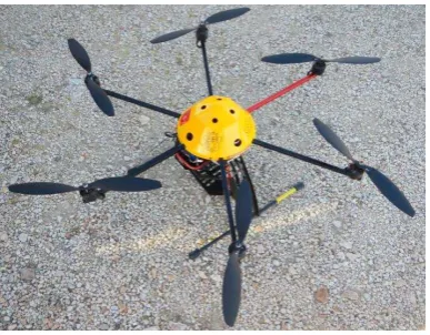
UAV (Fig. 1): MikroKopter Hexacopter with stabilized camera mount, supplied with 14.8 V batteries and 12-channel remote controlled transmitter with display for radio setting and telemetry. The on-board electronics includes GNSS, Navi control and Flight control cards for the stabilization of the flight. The on-board accessories include: live view video transmitter (5.8 GHz); data link for wireless communication
with the laptop (863 MHz); self-powered GNSS GSM tracker (sends a text message with the last known coordinates in case of loss of the UAV) and power supplies for the control of the camera mount; on-board LEDs and video transmitter. The diameter is 96 cm and the weight is 2.7 kg (including battery and camera mount), to which must be added the payload (up to 1.5 kg);
Total station Leica TCR 307;
Laptop Asus N55S series with Intel Core i7, 2.2 GHz, 8 GB ram, OS Windows 7 64-bit;
Workstation with Intel Core i7-3770K CPU, 3.5 GHz, 32 GB RAM, NVIDIA Quadro FX 1700, Windows Vista 64-bit OS.
Figure 1. MikroKopter Hexacopter
The software package available consisted of:
MikroKopter tool V1.80b, for the management of the flight plan;
Agisoft Photoscan professional, for image-based 3D reconstruction;
Photoshop CS 5 extended, for image processing;
Geomagic Studio 12 (evaluation copy), for the management and analysis of point clouds and 3D polygonal models;
Autodesk AutoCAD Raster Design 2013, for the vectorization of the planimetry.
2.2 Survey operations
second year two large areas were covered with the UAV: the temple and its surroundings, and the southern sector.
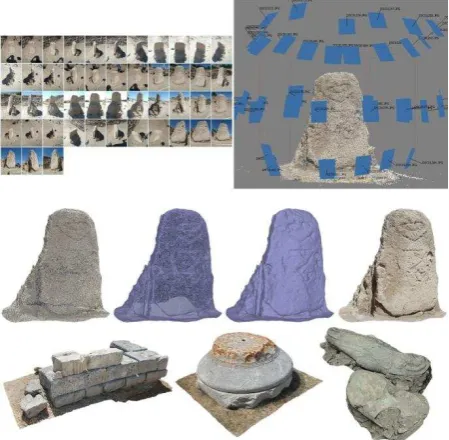
2.2.1 Terrestrial survey. Following the 3D reconstruction pipeline (Remondino, El-Hakim 2006, Russo, Remondino 2012), single monuments or special finds (i.e. objects with dimensions from 1 to 10 m) were surveyed with terrestrial SfM procedures. The models obtained are mainly used for visualization purposes and in some cases for measuring architectural elements (Fig. 2).
As far as camera calibration is concerned (Remondino, Fraser 2006), Agisoft Photoscan estimates both internal and external camera orientation parameters while carrying out photo alignment. Although it is known that calibration and alignment should be two separate processes, better options than self-calibration were not available at that moment.
The processing times (30 to 110 minutes) depended on the number and resolution of the processed images, the quality of the model, the number of triangles of the mesh, the texture resolution, and the performance of the workstation.
Figure 2. 3D models realized with terrestrial SfM procedures
2.2.2 UAV survey. Unlike previous examples, the survey by UAV (Eisenbeiss 2009, Sauerbier, Eisenbeiss 2010, Chiabrando, Lingua, Piras 2013) required a range of preliminary steps. The first and most important one was the flight planning. The software manages georeferenced images imported from Google Map, on which the operator has to place the flight configuration. The flight plan can be configured in two customizable patterns (grid and circular) for a maximum of 32 waypoints for flight. Moreover, the user must set the speed of the UAV, as well as the flight altitude (calculated from the take-off position), the distance between the waypoints, the retention time on the waypoint, the angle of sight of the camera and the shooting mode (e.g. at each waypoint, or every few waypoints, or every few seconds). Once all the parameters have been entered, the file is sent to the UAV via datalink. During the flight the telemetry and position of the drone are displayed in real time on the laptop (Fig. 3).
Figure 3. Flight plan
A second operation involved the positioning of the GCPs, which allow the correct orientation on the ground of the model. It is important to establish an accurate distribution of GCPs in order to cover the entire survey area. Each mobile target was measured with total station to obtain the coordinates relative to the reference system used within the area of excavation. Since a differential GNSS were not available, a sufficient number of surveying marking nails was fixed in the structures. They could be used for a future precise georeferencing of the survey area. Before proceeding with the flight it was essential to check the accuracy of the designed flight plan. In fact, even using georeferenced images, we often realized that we could not correctly place it. The reason of this inaccuracy is related to the resolution of the image and the intrinsic error of the GNSS receiver mounted on the drone. The problem was solved by performing a pre-flight to check for the correctness of the plan, adapting it to the actual conditions.
Once all the parameters had been verified, it was possible to begin the survey. Although the UAV proceeds automatically following the loaded settings, the experience of a specialized operator is needed to manage the takeoff and landing and in any case to overcome anything unexpected (wind, vegetation, infrastructure, loss of GNSS signal, etc.). It is advisable to work under optimal conditions of wind and light-shadow (an event that rarely occurs in south Italy), in particular by avoiding the times of the day when the shadows are too long or when the sun reflecting on the stones affects the exposure of the images. The ideal condition would be a cloudy sky at the end of the morning, which guarantees a diffused light. Finally, it is essential that the area to be surveyed is clear of the weeds that cover the archaeological ruins, in order to limit the visibility issues that can potentially affect the outcome of the operation. Another factor to consider is the weight of the SLR camera mounted on the UAV (725 g), which, although falling within the payload, has limited the flight to 8 minutes.
Regarding the temple, the flight plan provided a grid pattern of 48 waypoints spaced of 4 m on the x axis and 16 m on the y axis, with the speed of the UAV set to 1.2 m/s, with an altitude of 10 m, for a total of 151 vertical images taken every 2 seconds.
Thus, one shot every 2.4 m, corresponding to an 70% overlap between the images in relation to the flight altitude.
Given the considerable size of the area (about 2500 m2), the high number of waypoints and the aforementioned limitation on the autonomy of the batteries in relation to the payload of the device, the cover was completed with two flights.
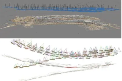
Regarding the southern sector and the great altar, the flight was designed according to a grid pattern of 24 waypoints spaced 16 m on the x axis and 4 m on the y axis. The same speed and frequency of image capture of the previous flight was set, but with an altitude of 12 m, taking a total of 76 vertical shots. In addition, 27 terrestrial images were taken around the altar to "strengthen" the model (Fig. 4).
In this case the whole operation required approximately 45 minutes.
Figure 4. 3D model of the southern sector with camera positions
In both flights, the SLR camera was set to shoot in aperture priority (11), with focal length 18 mm, ISO 100, fixed focus and auto white balance. The elaboration of the models required 4 hours and 2 hours respectively.
3 RESULTS
As previously mentioned, the models obtained by terrestrial photogrammetry have been created mainly for visualization purposes. Whereas the primary aim of the survey from UAV - over the testing and refinement of the methodology - was the elaboration of orthophotos, in order to verify the reliability of the planimetry currently in use and to correct and update it. As a case study we have chosen the area of the temple (Table 5).
Altitude [m] 10
Focal Length [mm] 18
Sensor Resolution 5184x3456
Sensor Width [mm] 22.3
Sensor Height [mm] 14.866666666666665 Sensor Pixel size [mm] 0.004301697530864197 Footprint Width [m] 12.38888888888889 Footprint Height [m] 8.259259259259258
GSD [m] 0.002389831961591221
Table 5. GSD Calculation Report
The orthophoto was imported and vectorized into AutoCAD Raster Design 2013 (Fig. 6). The result is a planimetry in actual size, which can be reduced to the desired scale (e.g. in archeology the 1:50 scale is the canonical one for the general planimetries of the excavation area) (Medri 2008).
Figure 6. Orthophoto of the temple vectorized
The unique planimetry of the building, drawn by Rosario Carta, dates back to 1912 (Orsi 1916). In addition, a campaign of restoration and consolidation was carried out in 1961, which has further changed its appearance.
The discrepancy between the old planimetry and the current situation is immediately evident, especially in the arrangement of the stone blocks (Fig 7). Moreover, some portions of structures brought to light at that time are no longer visible or have been removed, while others do not appear. The structures close to the temple have been recorded or reprocessed during the excavations carried out in recent years using a pantograph, which reproduces directly on paper a 1:20 scale plan.
Figure 7. Old (left) and new planimetry
The 3D model was analyzed with the appropriate software, obtaining further data: sections, contour lines and DEM (from which it is readily apparent the overlap between the various rows of the foundation blocks of the temple, Fig. 8). In addition, a PDF 3D file was created for the sharing and rapid visualization of the model (although of lower quality for portability reasons).
Figure 8: DEM of the temple
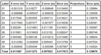
The GCPs coordinates on the model were compared with those derivable directly in the field (Table 9).
Finally, the measurements obtained on the traditional
Table 10. Comparison between old and new measures
The examples given show differences of 46 cm on average: with a maximum of 88 cm (distance right side-steps, inconsistency probably linked to renovation works) and a minimum of 15 cm (left side).
3.1 The approach with open source software
As an experiment, the different kinds of close-range blocks (Barazzetti, Remondino, Scaioni 2010) were processed with two open source applications: Python Photogrammetry Toolbox (Gonizzi Barsanti, Gherdevich, Degrassi 2011) and VisualSFM (Remondino, Del Pizzo, Kersten, Troisi 2012). For reasons of time and low experience, the MicMac suite has not been tested. In case of closed blocks and with a limited number of images (in particular those relating to individual architectural elements, special finds or small monuments), the alignment was successfully completed (Fig. 11).
Figure 11: Alignment of closed blocks with open source software
In case of open blocks with a high number of images, the operation required more time to process, often ending with program crash and however with obvious alignment errors ( Fig. 12).
Figure 12: Alignment of open blocks (dataset of the temple). With PhotoScan the result is positive (above), while with
VisualSFM is completely wrong
4 CONCLUSIONS
The procedures and the available software used for both terrestrial and UAV surveys have proven to be extremely reliable and valid for the purposes for which they were proposed. In particular for surveying large areas the results have ensured on the one hand, unpublished and accurate information, and on the other hand, relevant data to evaluate and quantify the inaccuracy of the traditional survey .
Another important fact concerns the time required to complete the entire workflow. It turned out to be considerably lower than that which would be necessary by using the old techniques of documentation. About 42 hours are needed to complete the most complex project (included 36 hours for the vectorization). In more detail, the ratio between the field work and the 3D model processing was 1:4 (i.e. one hour of work in the field was equivalent to four hours in the laboratory).
Some critical issues occurred in the preliminary phase of the operation. As already said, in the verification of the flight plan designed in the laboratory (which required the corresponding adjustments directly in the field), and in the configuration of the SLR camera for the acquisition of the vertical images. In fact, it was necessary to set different parameters depending on the light conditions. In addition, the SLR camera greatly affected the performance of the batteries of the UAV because of its weight. Under the present conditions, one battery (of the six available) is used for the test flight, from one to three for the survey flight and the others for photos of simple but necessary excavation documentation. Thus, it would be essential to increase the flight range to optimize the work in the field. One solution could be the use of new mirrorless cameras, which have a similar performance to the SLR, but weigh less.
Regarding the georeferencing of the 3D models, the use of a differential GNSS in the next excavation campaigns is mandatory.
As seen above, the approach with open source software did not give satisfactory results, or at least not more advantageous than proprietary applications employed for the project.The aim is to use these data sets of images with the application MicMac, the only open source tool that allows to keep under control the entire photogrammetric process.
To conclude, we can say that, as far as the archaeological record is concerned, the techniques and the procedures for surveys and 3D documentation tested are shown to be not only relatively cheap, but also more accurate, fast and versatile than the traditional ones. These results should be reported to the tools and the software package available, and to the experience of the working team, composed of people with exclusively archaeological knowledge.
Since only two areas of the site have received an aerophotogrammetric coverage, the methodology of this now tried and tested survey will be replicated in the remaining sectors to yield a total mapping of the Sanctuary.
At the moment, the vector and raster data have been requested by the Soprintendenza of Calabria, in order to be included in the GIS (still under construction) of the archaeological park of Kaulonia.
APPENDIX
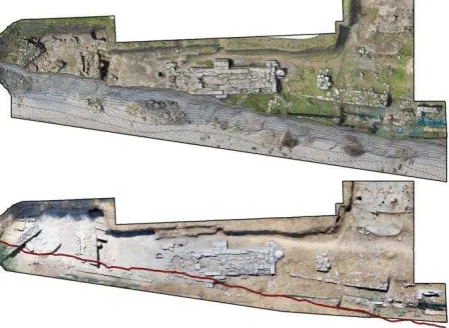
Figure 13: Orthophotos of the southern sector before (below) and after the seastorm. The red line indicates the current edge of
the natural terrace
This disaster has confirmed in the worst way the need of employing the UAV platforms for both simple photographic documentation and even more so for the photogrammetric survey with the purpose of monitoring and updating maps.
AKNOWLEDGEMENTS
The authors would like to thanks the entire team involved in the excavations of the Sanctuary. A special thanks to the pilot Andrea Palla for having provided the features of the UAV.
REFERENCES
Barazzetti, L., Remondino, F., Scaioni, M., 2010. Automation in 3D reconstruction: results on different kinds of close range blocks. In: International Archives of the Photogrammetry, Remote Sensing and Spatial Information Sciences, Newcastle upon Tyne, UK, Vol. XXXVIII, part 5, Commission V Symposium, pp.55-61.
Chiabrando F., Lingua A., Piras M,. 2013. Direct photogrammetry using uav: tests and first results. In: International Archives of the Photogrammetry, Remote Sensing and Spatial Information Sciences, Rostock, German, Volume XL-1/W2, pp. 81-86.
Eisenbeiss, H., 2009. UAV Photogrammetry, Zurich.
Gonizzi Barsanti S., Gherdevich D., Degrassi D., 2011. Use of low cost UAV systems in archaeological research and disclosure
http://www.academia.edu/1122557/USE_OF_LOW_COST_UA V_SYSTEMS_IN_ARCHEAOLOGICAL_RESEARCH_AND _DISCLOSURE
Medri, M., 2008. Manuale di Rilievo archeologico, Roma.
Orsi, P., 1916. Caulonia. Campagne archeologiche del 1912, 1913 e 1915, in Monumenti Antichi dei Lincei XXIII, cc. 685-944.
Parra, M.C., 2011. Dal Santuario di Afrodite a Punta Stilo, guardando alla città e al territorio, dopo oltre un decennio di ricerche. In Kaulonía, Caulonia, Stilida (e oltre), III. Indagini topografiche nel territorio, pp. 3-44.
Remondino, F., Del Pizzo, S., Kersten, T.P., Troisi, S., 2012. Low-Cost and Open-Source Solutions for Automated Image Orientation – A Critical Overview. In Progress in Cultural Heritage Preservation, 4th International Conference, EuroMed 2012, Lemessos, Cyprus,LNCS 7616, pp. 40-54.
Remondino, F., El-Hakim, S., 2006. Image-based 3D modelling: a review. In: The Photogrammetric Record, Vol. 21 (115), pp. 269-291.
Remondino F., Fraser C., 2006. Digital camera calibration methods: Considerations and comparisons, in International Archives of Photogrammetry, Remote Sensing and Spatial Information Sciences, Vol. XXXVI, part 5 pp. 266-272.
Russo M., Remondino F., 2012. Laser Scanning e Fotogrammetria: strumenti e metodi di rilievo tridimensionali per l'archeologia. In: Teoria e metodi della ricerca sul paesaggio d'altura, pp. 141-170, Mantova 2012.