PATIENT REGISTRATION
Computer Vision & Remote Sensing, Technische Universit¨at Berlin, D-10587 Berlin, Germany - [email protected] b
Framefield GmbH, Paul-Robeson-Straße 46, D-10439 Berlin, Germany - [email protected] c
Fiagon GmbH, Neuendorfstr. 23b, D-16761 Hennigsdorf, Germany - (tomasz.bien,christoph.m,dirk.mucha,timo.kruger)@fiagon.de
Commission V,WG V/5
KEY WORDS:Medicine, Close Range, 3D Surface Reconstruction, Photogrammetry, Smartphone Imagery, Navigation
ABSTRACT:
In navigated surgery the patient’s body has to be co-registered with presurgically acquired 3D data in order to enable navigation of the surgical instrument. For this purpose the body surface of the patient can be acquired by means of photogrammetry and co-registered to corresponding surfaces in the presurgical data. In this paper this task is exemplarily solved for 3D data of human heads using the face surface to establish correspondence. We focus on investigation of achieved geometric accuracies reporting positioning errors in the range of 1 mm.
1. INTRODUCTION
In navigated surgery the position and movement of a surgical in-strument with respect to the patient’s body is assisted by compu-tation. Often, as in the setting considered in this work, the posi-tioning is achieved by an electromagnetic posiposi-tioning device. It provides the coordinates of the surgical instrument, but does not directly provide patient-related positioning. Usually, presurgi-cally acquired data plays an important role regarding the planned surgical intervention.
These circumstances ask for a measurement procedure to inte-grate patient with surgical instrument and presurgical data. This can for instance be a movement of the surgical instrument across some well-defined landmark locations on the patient’s skin. This work, however, is concerned with a photogrammetric method for co-registration of the three components.
The photogrammetric reconstruction of human faces is achieved on the basis of several images acquired with an Ipad smartphone camera. Stereo reconstruction is done for the face surface as well as for markers known in the electromagnetic navigation system of the surgical instrumentation. Marker correspondences are used to transform the reconstructed face surface from the photogrammet-ric model coordinate system to the electromagnetic coordinate system.
A correspondence estimation between the photogrammetric and the presurgically acquired face surfaces is used to transform also the presurgical data into the electromagnetic coordinate system.
In the following the functionality of the system is explained and demonstrated. The paper focusses on the investigation of the achieved overall system accuracy.
2. RELATED WORK
Before and during treatment the task of image-based co-registration of patients with available 3D information does occur frequently in medicine. In a plastic surgery setting the use of smartphone
imagery as a replacement of more expensive imaging devices has been considered by (Koban et al., 2014). Using upto 16 images for a 3D co-registration effort they report promising accuracies. However, for experiments with only 3 to 6 images they observed large deviations.
Previously, commercial 3D surface imaging systems have been evaluated by (Sch¨offel et al., 2007) for breast cancer treatment. In their experiments they detected known shifts of phantoms and volunteers with an accuracy of 0.40 0.26 mm and 1.02 +/-0.51 mm, respectively.
(Bert et al., 2005) use surface registration to estimate rigid motion of patients in radiotherapy to achieve co-registration with refer-ence data. The estimation referred to a specific region of inter-est on the patients’ bodies. This task occasionally needs to be solved under real-time requirements considering potential mo-tion of the patient during radiotherapeutic treatment. (Peng et al., 2010) and (Alderliesten et al., 2013) evaluate the accuracy of the AlignRT3C system, an image-guided stereotactic positioning system. (Peng et al., 2010) find agreement of alternative measure-ments in the range of 1.3 mm. (Alderliesten et al., 2013) conduct experiments with systematic errors of 1.7 mm and additional ran-dom errors of 1.5 mm.
In a similar setting (Bauer et al., 2011) investigate a markerless solution for coarse patient registration using Microsoft Kinect as a projection-imaging-based 3D measurement device. They report translational errors w.r.t. computed tomography data in the range of 13.4 mm.
(Wang et al., 2011) use image-based detection and tracking for co-registration with angiography and intravascular ultrasound im-ages. Also in endoscopy or laparoscopy corresponding methods are used (Wengert et al., 2006, Maier-Hein et al., 2013).
3. METHOD
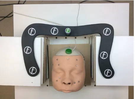
markers were used. For simplicity reasons seven out of those markers were arranged on a planar frame, the eighth was lifted out of the frame plane by approximately 5 cm (Fig. 1).
Figure 1: Marker arrangement on frame largely circumferencing the patient’s face to limit extrapolation. Phantom and image were used for the accuracy investigation described in Section 5.
The markers were designed allowing to detect them using an ini-tial relatively simple circle extraction with essenini-tially zero false negative rate. In a second processing step the false positive rate is decimated and precise localization is achieved using template-and correlation-based matching. Finally, the given marker coor-dinates allow both to avoid any false marker detection - as long as the marker is unoccluded - and to individually identify each marker.
Subsequently, the exterior orientation of the images is estimated according to a state of the art approach. Specifically, spatial re-section using the markers provides intial values, small-scale tie points help to improve, and least-squares bundle adjustment is used for optimization.
Tie point extraction deserves special attention as human skin as well as operation cover sheets often tend to show only few point features. Therefore, they are not used as absolutely necessary components in the developed procedure.
Dense surface matching is conducted using stereo image pairs. Prior to the matching it is tried to individually improve the rela-tive orientation of the stereo pair given by the preceeding exterior orientation processing step. The result of the processing of each stereo pair is a point cloud.
Point clouds are noise filtered, smoothed, and finally combined using Iterative Closest Point (ICP) matching. As the orienta-tion of the individual clouds is already given in the same global
images were recorded and processed as two stereo pairs whose point clouds were combined for final reconstruction. Distance from the object was chosen to be approximately 50 cm, baseline lengths to be between 4 and 10 cm.
5. EXPERIMENTAL EVALUATION
In this work we report 3D reconstruction accuracies based on comparison of the results of photogrammetric surface reconstruc-tion with reference data of superior quality. However, initially we have to discuss the legitimate question which accuracies are to be expected from the setting presented so far - for instance according to an approximative rule of thumb.
To make a cautious assessment let us assume that disparity esti-mation as well as point identification can be done with an accu-racy of 0.2 pixels. For the iPad images with an image size of 2592 by 1936 pixels we found that dense surface matching was more reliable after downsampling the images by factor 2. Calibration of the downsampled images gave a principle distance of approxi-mately 1200 pixels. For an object distance of 0.5 m and a base to distance ratio of 1/10 we obtain an accuracy of depth estimation of 0.8 mm. So the “rule of thumb” accuracy to be expected for 3D reconstruction would be approximately 1 mm.
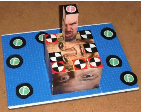
For a realistic practical accuracy evaluation two experiments were conducted. First a phantom was constructed with marked points on realistically textured surfaces in between control point mark-ers arranged as in the system’s anticipated setup (Fig. 2). In order to be able to easily determine accurate control and refer-ence point coordinates, the phantom was contructed from Lego toy bricks and parts. The known standard size of the Lego grid was used to calculate coordinates. In the second experiment a human face phantom was used with screw markers driven into the phantom providing identifiable yet not extraordinarily salient reference points on the phantom’s face surface.
Figure 2: Phantom built from Lego bricks and textured with face image prints. The accuracy evaluation of experiment I is limited to the locations of the “pizza” markers.
Figure 3: Measurement image of the Lego phantom.
+/- 0.55 mm in all coordinate directions. Compared to the “rule of thumb” assessment this result fulfills the expections.
In the second experiment photogrammetric face reconstruction accuracy from three iPad images was to be determined. Twelve test data sets were acquired each consisting of three iPad images showing a face phantom and the frame with eight reference mark-ers allowing transformation from photogrammetric coordinates to electro-magnetically determined surgical navigation coordinates.
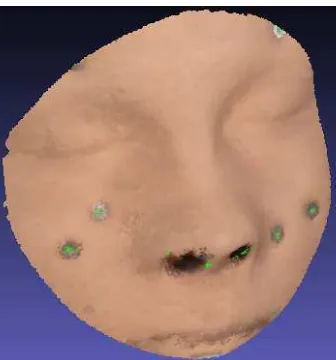
For the investigation of the face reconstruction the face phantom had been supplemented by a set of screws with screw heads at the level of the surface of the phantom (Fig. 5). As the phantom is equipped with an electro-magnetic sensor of the surgical nav-igation system, using screw head positions relative to this sensor the screw head centers can be coordinated in the electro-magnetic coordinate system for each of the twelve test data sets. As also the reference frame is equipped with an electro-magnetic sensor allowing to determine electro-magnetic reference marker coordi-nates, the test data set’s screw head positions can be transformed into the reference frame coordinate system. These coordinates are subsequently used as screw head reference coordinates.
As in the spatial resection the control point marker coordinates are given in reference frame coordinates, the photogrammetri-cally reconstructed face surface is also obtained in the reference frame coordinate system.
Figure 4: Scatter plot of “pizza” test marker errors and “logo” control point marker errors grouped by x-, y-, and z-coordinate. Red: systematic deviation of test points; green: standard devia-tion of test points from random deviadevia-tion only; blue: standard de-viation of test points from both systematic and random dede-viation; dark green: standard deviation of control points from random de-viation only; cyan: standard dede-viation of control points from both systematic and random deviation. The term “systematic” is used for deviations common to all points in test data set.
For the automatic determination of photogrammetric screw head coordinates the screws are extracted from the images by circle detection. In order not to miss any screw heads circles are de-tected with a substantial false positive rate regarding true screw images. Then the color of some pixels at the circle centers is replaced by green color - a color otherwise not present on the phantom’s surface. As this is done prior to the dense surface re-construction, the screw heads become small greenish blobs on the reconstructed 3D face surface. Besides that, the influence of the exchanged color values on the surface reconstruction can be considered marginal. The centers of gravity of the greenish blobs are extracted from the photogrammetric surface. Their 3D co-ordinates are considered screw head candidates. A point cloud matching between screw head reference cloud and photogram-metric screw head candidate cloud allows to separate false posi-tive from true screw heads.
Then reference screw head coordinates can be compared with photogrammetric screw head coordinates. For this investigation six screw heads surrounding the phantom’s nose were compared. With two out of the twelve data sets allowing to compare only five out of the six marker positions 70 screw head extractions could be used to compute standard deviations. The resulting standard deviations of x-, y-, and z-coordinates averaged over the twelve data sets are +/- 0.64 mm, +/- 0.38 mm, and +/- 0.87 mm, respec-tively.
Figure 5: Phantom with screw heads defining reference locations. Green blob indicates automatic detection of the screw head.
+0.9 mm and are comparable for x, y and z.
Figure 6: Mean of the differences between photogrammetric co-ordinates and electro-magnetically determined reference coordi-natesmx,my, andmzof the screw heads incm.
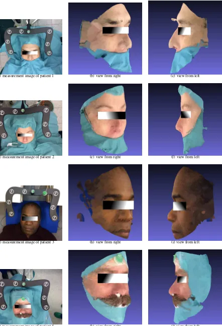
Finally, the system has been tested in different operating rooms under realistic lighting conditions with real patients voluntarily participating in the investigations. In Fig. 7 we present some re-sults by visualizing reconstructed surfaces acquired under vary-ing circumstances such as low illumination or weak texture.
6. CONCLUSIONS
We demonstrated that triplets of iPad smartphone images allow to reconstruct face surfaces of patients in an operation room setting with an accuracy sufficient for co-registration with preoperatively acquired medical data. The 3D reconstruction accuracy is in the range of 1 mm.
It is exemplarily shown that conventional smartphone camera im-agery can be successfully applied for 3D reconstruction, even if the major application requirement on the reconstruction is to fill-fil certain geometric accuracy reliably. The developed system has been tested in several clinical operation rooms and has shown to provide advantages compared to other methods regarding speed and simplicity of use while fulfilling requested accuracy require-ments.
In future other but face surfaces of patients should be recon-structed - being more challenging due to problems such as self-occlusion.
2762.
Bradski, G. and Kaehler, A., 2008. Learning OpenCV: Computer vision with the OpenCV library. ” O’Reilly Media, Inc.”.
Koban, K., Leitsch, S., Holzbach, T., Volkmer, E., Metz, P. and Giunta, R., 2014. [3d-imaging and analysis for plastic surgery by smartphone and tablet: an alternative to professional sys-tems?]. Handchirurgie, Mikrochirurgie, plastische Chirurgie: Organ der Deutschsprachigen Arbeitsgemeinschaft fur Hand-chirurgie: Organ der Deutschsprachigen Arbeitsgemeinschaft fur Mikrochirurgie der Peripheren Nerven und Gefasse: Organ der V.. 46(2), pp. 97–104.
Maier-Hein, L., Mountney, P., Bartoli, A., Elhawary, H., Elson, D., Groch, A., Kolb, A., Rodrigues, M., Sorger, J., Speidel, S. et al., 2013. Optical techniques for 3d surface reconstruction in computer-assisted laparoscopic surgery. Medical image analysis 17(8), pp. 974–996.
Peng, J. L., Kahler, D., Li, J. G., Samant, S., Yan, G., Amdur, R. and Liu, C., 2010. Characterization of a real-time surface image-guided stereotactic positioning system. Medical physics 37(10), pp. 5421–5433.
Rusu, R. B. and Cousins, S., 2011. 3d is here: Point cloud li-brary (pcl). In: Robotics and Automation (ICRA), 2011 IEEE International Conference on, IEEE, pp. 1–4.
Sch¨offel, P. J., Harms, W., Sroka-Perez, G., Schlegel, W. and Karger, C. P., 2007. Accuracy of a commercial optical 3d sur-face imaging system for realignment of patients for radiotherapy of the thorax. Physics in medicine and biology 52(13), pp. 3949.
Wang, P., Chen, T., Ecabert, O., Prummer, S., Ostermeier, M. and Comaniciu, D., 2011. Image-based device tracking for the co-registration of angiography and intravascular ultrasound im-ages. In: Medical Image Computing and Computer-Assisted Intervention–MICCAI 2011, Springer, pp. 161–168.
(a) measurement image of patient 1 (b) view from right (c) view from left
(d) measurement image of patient 2 (e) view from right (f) view from left
(g) measurement image of patient 3 (h) view from right (i) view from left
(j) measurement image of patient 4 (k) view from right (l) view from left