IMAGE ACQUISITION AND MODEL SELECTION FOR MULTI-VIEW STEREO
K. Wenzel, M. Rothermel, D. Fritsch, N. Haala
Institute for Photogrammetry, University of Stuttgart Geschwister-Scholl-Str. 24D, 70174 Stuttgart, Germany
[konrad.wenzel, mathias.rothermel, dieter.fritsch, norbert.haala]@ifp.uni-stuttgart.de
KEY WORDS: Photogrammetry, Surface Reconstruction, Multi-View Stereo, Dense Image Matching, Structure from Motion
ABSTRACT:
Dense image matching methods enable efficient 3D data acquisition. Digital cameras are available at high resolution, high geometric and radiometric quality and high image repetition rate. They can be used to acquire imagery for photogrammetric purposes in short time. Photogrammetric image processing methods deliver 3D information. For example, Structure from Motion reconstruction methods can be used to derive orientations and sparse surface information. In order to retrieve complete surfaces with high precision, dense image matching methods can be applied. However, a key challenge is the selection of images, since the image network geometry directly impacts the accuracy, as well as the completeness of the point cloud. Thus, the image stations and the image scale have to be selected according carefully to the accuracy requirements. Furthermore, most dense image matching solutions are based on multi-view stereo algorithms, where the matching is performed between selected pairs of images. Thus, stereo models have to be selected from the available dataset in respect to geometric conditions, which influence completeness, precision and processing time. Within the paper, the selection of images and the selection of optimal stereo models are discussed according to to photogrammetric surface acquisition using dense image matching. For this purpose, impacts of the acquisition geometry are evaluated for several datasets. Based on the results, a guideline for the acquisition of imagery for photogrammetric surface acquisition is presented. The simple and efficient capturing approach with “One panorama each step” ensures complete coverage and sufficiently redundant observations for a surface reconstruction with high precision and reliability.
1. INTRODUCTION
Acquiring 3D surfaces with image matching solutions is a flexible and cost effective method. Accuracy and resolution can be chosen freely with the selection of the camera and the image stations. A key challenge is to find the optimal configuration to retrieve the required resolution, precision and completeness in the resulting dataset. Finding an optimal focal length and network can be complex, in particular for objects with strong depth variations which are acquired at short distance.
The network layout is defined by many parameters, such as the camera itself, focal length, distance to the object, distance between stations and so on. Since photogrammetric surface acquisition is only based on angle observations – in particular the angle between corresponding pixels of multiple images, rules of an optimal network layout can be defined independent to the image scale. Thus, the same rules can be applied for capturing very small objects with a couple of millimeters size, as well as for the recording of sculptures or buildings. Also, they are independent to the platform and thus are applicable to terrestrial and aerial imagery.
Within the following sections, the key impact on accuracy and completeness for image based surface reconstruction are investigated. The focus is on dense surface reconstruction methods based on multi-view stereo, however, most of the rules are applicable to any photogrammetric data acquisition independent of the reconstruction method.
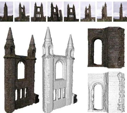
Figure 1 shows an image based data acquisition using a Olympus C5050 with 5 Megapixels resolution. A church ruin in St. Andrews, Scotland, was acquired with 43 images around the object in a circular shape. Structure from Motion reconstruction methods can be used to reconstruct camera pose (exterior
orientation), intrinsic camera parameters and sparse surface information using distinctive image features such as SIFT points [Lowe, 2004]. Subsequently, dense image matching methods can be applied to reconstruct surfaces. Within the example, a dense point cloud was derived with the dense image matching solution SURE, which was developed at the Institute for Photogrammetry of the University of Stuttgart [Rothermel et al., 2012]. The dense image matching also leads to range images, which can be used within volumetric range integration methods. Within the example, a volumetric range integration method with regularization similar to [Zach, 2008] was used.
Figure 1: Church ruin St. Andrews, Scotland. 43 images with 5 Megapixels acquired in a circle around the object. Left: point cloud
from dense image matching, right: meshed surface derived by volumetric range integration.
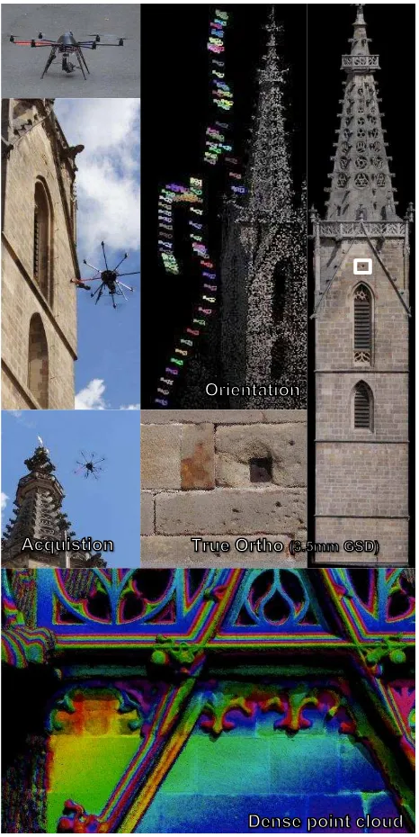
Façade acquisition by UAV in Rottenburg am Neckar Acquisition Orientation Dense point cloud True Ortho
Figure 2: Façade acquisition of a church tower in Rottenburg / Neckar using a UAV. Two images per second were acquired and automatically oriented using Structure from Motion methods. Subsequently, dense image matching was used to generate point clouds and true orthophotos
Figure 2 shows another example where Structure from Motion and dense image matching methods were used to acquire building facades. In order to generate a true orthophoto of a church tower 70m in height in Rottenburg / Neckar, Germany, an Unmanned Aerial Vehicle (UAV) was employed. The UAV, an octopter, carried a Panasonic DMC GX-1 system camera with 16 Megapixels resolution. It was used to acquire a sufficient amount of images for image based surface reconstruction of the whole façade, by exposing two images per second. The orientation was automatically derived using the Structure from Motion approach by [Abdel Wahab et al, 2012]. Subsequently, the dense image matching solution SURE was applied to derive a dense point cloud. Due to the high point density, a true orthophoto could be derived by projecting points onto a plane.
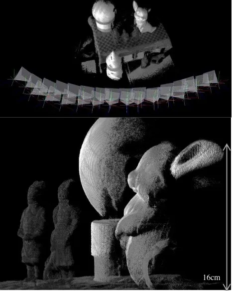
Figure 3: Image based data acquisition of cultural heritage objects at short distance. Sub-mm resolution and accuracy by using multi-camera
solutions at an acquisition distance of 0.5-1m. Red dots: camera stations, right: sparse point cloud, left: dense point cloud
Figure 3 shows an example for recording of cultural heritage objects [Fritsch et al., 2011; Wenzel et al., 2012]. Two tympanums at the royal palace of Amsterdam covering about 125m² area were acquired using a multi-camera system. About 10,000 images were acquired and used to derive a point cloud with 2 Bio. points and sub-mm resolution and accuracy.
For all shown examples, the key challenge was the selection of camera stations and the selection of suitable stereo models within the multi-view stereo step for dense surface reconstruction. Also, the selection of camera and lens according to the project requirements can be challenging. [Waldhäusl and Ogleby, 1994] introduced the CIPA 3x3 rules as reliable guideline for the photogrammetric recording of objects, in particular for buildings. Since then, the camera technology, but also the capability of automatic image processing methods changed. More images can be acquired in short time and processed automatically, which enables the derivation of dense surface information. For airborne data acquisition, images are already acquired at higher overlap of 80-90% in contrast to the former 60%, in order to be able to derive surface models by dense image matching [Haala et al, 2012]. The additionally acquired imagery and its processing do not lead to significant additional costs. In contrast, high overlap enables a reliable production pipeline for precise datasets with complete coverage. This approach also applies for any other image based data acquisition of surfaces, either terrestrial, in mobile applications or with UAVs.
Within the following section, the requirements of photogrammetric surface acquisition shall be discussed in respect to geometric conditions. Subsequently, the simple image acquisition guideline “One panorama each step” is proposed, which enables efficient capturing for dense surface reconstruction purposes.
2. GEOMETRIC CONDITIONS FOR PHOTOGRAMMETRIC SURFACE ACQUISITION
Independent of scene, the image acquisition has to be planned according to the needs regarding precision and resolution. The relation can be approximated for a stereo measurement in the stereo normal case with distance , baseline , focal length pixel pitch and disparity as [Kraus, 2007]:
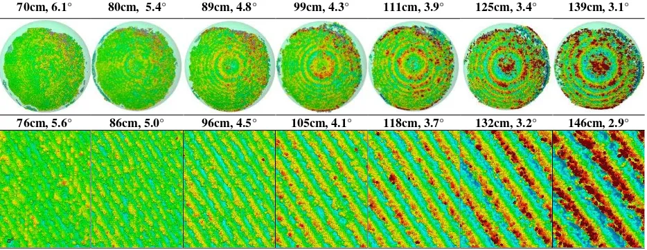
70cm, 6.1° 80cm, 5.4° 89cm, 4.8° 99cm, 4.3° 111cm, 3.9° 125cm, 3.4° 139cm, 3.1°
76cm, 5.6° 86cm, 5.0° 96cm, 4.5° 105cm, 4.1° 118cm, 3.7° 132cm, 3.2° 146cm, 2.9°
Figure 6: Evaluation of noise at the surface for very small intersection angles. A best fitting sphere and a best fitting plane were compared to the point cloud. With the decrease of intersection angles, the noise is increasing. The visible pattern represents the discretization error, since the disparity range
is very small and the subpixel measurement precision in image space is limited. The derivation of (1) by the depth leads to the propagation of
variance in depth in respect to the variance in the image:
Thus, the precision of depth for a point from a stereo measurement in relation to the measurement accuracy in image space can be expressed as:
Consequently, the precision of the photogrammetric measurement mainly depends on the two components , which represents the image scale, and , which represents the intersection angle. Typically, a wide angle lens is used in order to cover a large area at each station and to enable an accurate bundle adjustment – as discussed in section 3. The used camera defines the pixel size, and with that the angular resolution. According to the required depth precision, image scale and intersection angle should be chosen.
Small intersection angles and image scales lead to high completeness due to the high image similarity and the good matching performance, but also poor depth precision due to the weak geometrical conditions. In contrast, large intersection angles and large image scales provide better depth precision, but suffer from the lower image similarity. Thus, the point density becomes lower. In order to find the optimal solution, different extreme cases with low image scales and intersection angles, but also with high angles and scale are shown and discussed within the following section.
2.1 Small baseline, intersection angle and image scale
In order to find the minimum baseline, the impact of small intersection angles on the precision of dense image matching was evaluated. A calibrated rig of two industrial cameras (IDS 2280 with 5MP) at a baseline of 7.5cm was used to acquire a stereo image pair of a scene (figure 4). The scene contained a sphere and a plane. In order to evaluate the precision of the 3D points derived by the dense image solution in respect to image scale and the resulting intersection angles the acquisition was performed at several distances between 70cm and 140cm.
Figure 4: Evaluation setup with two industrial cameras (IDS 2280, 5Mp) at 7.5cm baseline and additional texture projection.
The relative orientation for the camera rig was determined using the software Australis in combination with a calibration pattern. The measurement of corresponding points was performed using an ellipsoid fitting for the targets with a precision better than 0.1 pixel. For each stereo pair, one 3D point cloud was computed using the dense image matching solution SURE (figure 5).
Figure 5: Image of evaluation scene and resulting point clouds for several distances
Since only the precision in object space with respect to intersection angle and image scale shall be evaluated, a best-fit plane and a best-fit sphere were estimated for the 7 point clouds. Thereby, the impact of transformation uncertainties to reference data can be avoided. The fitting of the sphere and the plane, as well as the visualization of differences was performed using the software GOM Inspect. Outlier points with a residual larger than were not considered. Thus, only local noise on the surface is estimated, while neglecting outliers as occurring due to missing redundancy of multiple stereo models.
Best fitting sphere
[m] 0,70 0,80 0,89 0,99 1,11 1,25 1,39
[°] 6,13 5,39 4,79 4,33 3,88 3,44 3,09
[mm] 0,30 0,34 0,39 0,43 0,48 0,54 0,60
[mm] 0,39 0,46 0,51 0,62 0,76 1,06 1,35
[px] 0,14 0,13 0,11 0,11 0,11 0,12 0,12
Best fitting plane
[m] 0,76 0,86 0,96 1,05 1,18 1,32 1,46
[°] 5,62 4,99 4,46 4,08 3,65 3,25 2,93
[mm] 0,33 0,37 0,41 0,45 0,51 0,57 0,63
[mm] 0,45 0,52 0,66 0,76 1,00 1,26 1,58
[px] 0,13 0,12 0,12 0,12 0,13 0,13 0,13
Table 1: Evaluation results. Distance , intersection angle , ground sampling distance , std. deviation at object and in image space .
Figure 6 and table 1 show the results. As expected, the point position precision decreases with an increase of the distance to the object . By using the relation between object and image precision for the stereo normal case from the introduction of section 2, equation 3, the corresponding precision in image space can be determined.
In the presented example, the baseline amounted to 7.5cm, focal length to 8mm and the pixel pitch to 3.45µm. While the resulting measurement precision in image space is constant for all configurations, the precision in object space decreases due to the small intersection angle and the decrease of the image scale. The small intersection angle leads to small disparities ranges and thus, to an insufficient depth discretization. Since the subpixel-precision is limited discretization errors occur, as visible on the right in figure 6. Thus, very small angles should be avoided if only one stereo model is processed. For multiple stereo models, small such measurements can be useful for the validation of measurements with strong intersection geometry.
Even though small intersection angles lead to noisy results, models with small base lines should be acquired and used within the surface reconstruction. Since large baseline models have lower image similarity – which is challenging for the matching method, small baseline models are required additionally. Furthermore, highly overlapping imagery leads to high redundancy, which is beneficial for the precision in object space. Figure 7 shows the result for a similar scene and the same cameras containing 28 images used in a multi-stereo configuration. The smaller distance to the object of 60cm improves the geometrical condition and the redundancy leads to noise reduction and outlier removal.
As visible in table 1, the measurement in image space amounts to about 0.13 pixels for the presented example. This precision is typically slightly lower due to the precision of matching. The matching precision is in particular depending on texture and geometric conditions. Here, video projectors were used to provide fine texture on a white object, which leads to a good signal to noise ratio and is beneficial for the image matching. Furthermore, the precision in object space is decreased for large intersection angles, since the decreasing image similarity is challenging for the matching method. As shown by [Rothermel et al., 2011], it typically varies between 0.1 and 0.3pixels. If the intersection angle becomes too large, the matching might fail – in particular for complex surfaces. Thus, a maximum baseline should be chosen according to the considerations in the following chapter.
Figure 7: Multi-view acquisition result of comparable scene, containing a sphere with 7.5cm radius at about 60cm distance (7.1°). The standard
deviation to the best fitting sphere amounts to 0.25mm.
2.2 Large baselines and surface tilts
In order to evaluate dense surface reconstruction for large baselines and intersection angels, the performance of the matching algorithm has to be considered. While the geometric conditions are optimal for rather large intersection angles (e.g. 90°), the matching performance is decreased for large intersection angles since the image similarity is reduced. This image similarity is mainly dependent on this angle, but also the angle between normal vector and viewing ray. The latter is particular important for complex surfaces, where surfaces are often tilted more than 20° in relation to the viewing direction and no observation of these surfaces in nadir direction is possible. Thus, flat surfaces can be matched successfully on larger angles than tilted surfaces.
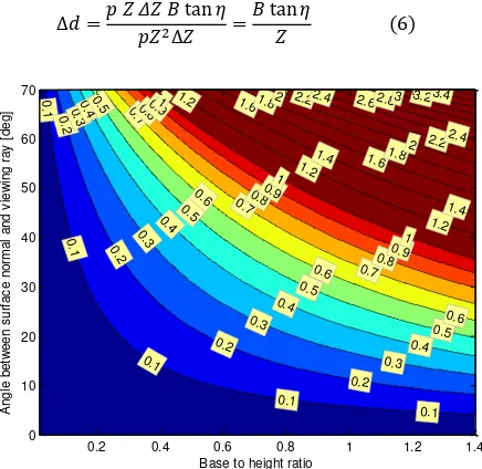
Figure 8: Acquisition of the surface (blue) with a normal vector by a camera with focal length and pixel pitch . The shift in depth between two neighboring pixels leads to a disparity gradient .
16cm
Hence, the impact of the surface normal in respect to the intersection angle on the precision of the disparity measurement shall be found. As shown in the introduction of section 2 (2), the relation between variations in depth and the corresponding variation in the disparity measurement can be expressed by:
According to that, we can express a depth change between two neighboring pixels on the object in relation to the resulting disparity change in image space (figure 8). Using that, the disparity variation for a certain angle between surface normal and viewing direction can be estimated. If the two different viewing rays of neighboring pixels are approximated to be parallel, this angle can be expressed by:
Thus, the disparity change can be approximated by:
Figure 9: Relation between base/height ratio, angle between surface normal and viewing ray and the resulting disparity shift. If the shift becomes large, e.g. greater than 1 pixel, the matching becomes more difficult and can fail. Thus, very base to height ratio should be avoided.
Thus, the relation base-to height ratio, surface normal and the resulting shift in the disparity for a certain depth change can be approximately determined and visualized as shown in figure 9. Sufficient image similarity is given, if the disparity gradient is rather small. Therefore, the gradient in depth of two neighboring pixels is considered. If the resulting disparity shift is too large, e.g. greater than 1 pixel, the matching might fail. Typically, scenes with non-flat surfaces contain angles for the surface with up to 60° tilt angle. Thus, the availability and use of a sufficient amount of stereo models with maximum 30° intersection angle should be available. This threshold depends on the robustness of the method against wide baselines. Nevertheless, for dense surface reconstruction a sufficient amount of models within this limit is beneficial - independent of the method, in order to achieve high surface information density and reliability.
2.3 Exterior orientation accuracy
In order to investigate the behavior of dense image matching with respect to the accuracy of the exterior orientation of the images, a point cloud of a reference object with known surface was evaluated. This reference object with the name “Testy” was developed by Prof. Dr. Ralf Reulke and Martin Misgaiski from the Humbold University Berlin for the evaluation of 3D measurements methods [Reulke et al., 2012]. It is about 35cm high and contains different geometric structures. A GOM Atos 1 structured light system was used to acquire a reference dataset for the surface with a precision of 10µm.
Figure 10: Photogrammetric acquisition of the white test object “Testy” using artificial texture from 3 video projectors.
In order to acquire a point cloud of the white object, 3 video projectors were used to project texture from all directions. Subsequently, 46 images were acquired using a Nikon D7000 DSLR in a circular shape around the object. The interior and exterior orientation was determined automatically using the software VisualSFM [Wu, 2011] without prior calibration. The orientations were used within the dense image matching solution SURE to derive a dense point cloud. The scale for the resulting point cloud of about 80 Mio. points was estimated using a best-fit cylinder in the cylinder shaped part of both point clouds. The transformation to the reference object was determined using the Iterative Closest Points algorithm [Besl & MacKay, 1992].
Figure 11: Result of Structure from Motion reconstruction by the software VisualSfM. Orientations and sparse point cloud for 46 images.
In order to compare the difference to the reference surface
visually, the software Cloud Compare
(http://www.danielgm.net/cc/) was used. A difference to the mesh was computed and visualized, as shown in figure 12. The results indicate the improvement of the precision with increasing angles and the improvement due to high redundancy by means of many stereo models, as visible in the second image. Here, each pixel is observed in many images, which enables outlier rejection and noise reduction. The unexpected inhomogeneous distribution of the error indicates errors of the exterior orientation.
Reference Multi-Stereo Single, 3° Single, 15°
[mm]
Figure 12: Difference of point cloud to reference surface, visualized using the software CloudCompare. Reference surface from structured light, result from multi-stereo, result from single stereo model at 3° mean intersection angle, result from single model at 15°.
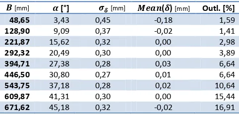
In order to evaluate the dataset quantitatively, a point cloud for 9 stereo models with different baselines to a particular base image were computed. The reference was projected into the base image, in order to compare the differences between the ranges for each pixel in direction of the viewing ray. Table 2 shows the results. The accuracy in object space increases with the baseline. Also, the amount of outliers increases, since the matching fails more likely, as discussed in section 2.2. Additionally, the overlap of the two images becomes lower, which leads to lower completeness. The varying mean of the difference again indicates errors in the exterior orientation.
[mm] [°] [mm] ( ) [mm] Outl. [%]
48,65 3,43 0,45 -0,18 1,59
128,90 9,09 0,37 -0,02 1,41
221,87 15,62 0,32 0,00 2,98
292,32 20,49 0,30 0,00 3,89
394,71 27,38 0,28 0,03 6,64
446,50 30,80 0,27 0,01 6,64
543,75 37,18 0,28 0,02 10,64
609,87 41,31 0,30 0,00 15,44
671,62 45,18 0,32 -0,02 16,91
Table 2: Differences of the point cloud from 9 single stereo models to the reference surface in ray direction. Baseline, intersection angle, std.
deviation of difference, mean of difference, amount of outliers.
For high accuracy applications, high quality orientations are required. In this case, a bundle adjustment with ground control would improve the result, since scaling errors, drift problems in the bundle and registration errors can be reduced. Furthermore, the used adjustment of VisualSfM uses only a minimum of parameters for the interior orientation (e.g. 1 distortion coefficient only) and feature points with a relatively low measurement precision (~1pixel). Consequently, an additional bundle adjustment should be performed providing a sufficient model for the intrinsic parameters of the camera. Therefore, the results from the Structure from Motion solution like VisualSfM can be used as initial values. Beside the introduction of ground control, the usage of a matching method for the tie points with better precision improves the accuracy of the bundle, as shown by [Cramer et al., 2013, Table 3]. The accuracy in image and object space can be reduced significantly by using tie points with subpixel accuracy.
3. IMAGE ACQUISITION GUIDELINE:
“ONE PANORAMA EACH STEP”
For manual image position selection, a consideration of all parameters for an optimal set of stereo pairs is a challenge. Each scene, camera and lens requires a different distribution of camera stations. The CIPA 3x3 Rules, presented by Waldhäusl and Ogleby in 1994, were widely used for image acquisition for simple photogrammetric documentation of architecture. They are applicable for many scenes.
Nowadays, digital cameras and automatic algorithms enable efficient acquisition and processing also for large datasets. In particular for dense surface reconstruction tasks, a higher number of images is required. Thus, it is unnecessary to find the minimum number of optimal stations. In contrast, the risk of gaps in the dataset due to an insufficient amount of images must be minimized. For this purpose, we propose an adapted rule set for dense surface reconstruction applications, including a simplified approach for the manual selection of stations. It is a systematic approach with three easy steps enabling efficient data acquisition without gaps.
3.1 Image acquisition: “One panorama each step”
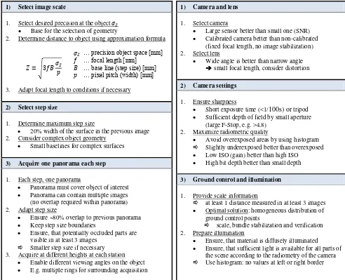
The proposed image acquisition strategy “One panorama each step” is a simple approach with particular focus on photogrammetric surface reconstruction. Since many images are required for redundancy purposes, we propose an easily memorable strategy enabling efficient capturing while ensuring completeness. The strategy – summarized in table 3, contains 3 steps:
1) Select image scale 2) Select step size
3) Acquire one panorama each step
Within the first step, the image scale is selected according to the precision needs. In particular for high accuracy applications, the image scale is the limiting parameter for the selection of focal length and stations. The shortest available focal length should be chosen if the acquisition distance is not restricted, e.g. due to obstacles. According to the selected focal length, the distance can be estimated according to the desired precision on the object . According to the relation between precision in image and object space discussed in section 2, the distance can be determined as:
√
If we approximate the measurement precision in image space to 1/3 pixels, we can use:
√
… precision object space [mm] … focal length [mm]
… base line (step size) [mm] … pixel pitch (width) [mm]
A precision of 1/3 pixels is typical for the dense image matching solution SURE, but can be adapted according to other solutions. Furthermore, aiming at a higher precision in object space is suggested, since additional impacts, such as exterior orientation errors will reduce the effective accuracy. However, improvements can be expected if high redundancy due to large image overlap is available. While capturing, the distance to the object should always be applied to the surface with the most depth to camera during acquisition.
1) Select image scale
1. Select desired precision at the object
Base for the selection of geometry
2. Determine distance to object using approximation formula
… precision object space [mm]
√ … focal length [mm]… base line (step size) [mm] … pixel pitch (width) [mm]
3. Adapt focal length to conditions if necessary
2) Select step size
1. Determine maximum step size
20% width of the surface in the previous image 2. Consider complex object geometry
Small baselines for complex surfaces
3) Acquire one panorama each step
1. Each step, one panorama
Panorama must cover object of interest
Panorama can contain multiple images (no overlap required within panorama) 2. Adapt step size
Ensure ~80% overlap to previous panorama
Keep step size boundaries
Ensure, that potentially occluded parts are visible in at least 3 images
Smaller step size if necessary 3. Acquire at different heights at each station
Enable different viewing angles on the object
E.g. multiple rings for surrounding acquisition
Table 3: Summary image acquisition: “One panorama each step”
The step size between each image should rather be too small than too large. Thus, the risk of data gaps is minimized, while ensuring highly overlapping imagery. The latter provides redundant measurements, which decreases noise of the surface data and enables the rejection of outliers during the surface reconstruction step. In order to estimate a reasonable maximum step size, the width of the surface being observed in the previous image can be used. Maximum 20% width of this surface should be used as step size.
At each step, a panorama is acquired. Multiple images can be used at each step to cover the whole desired object if it can’t be covered with one image only. These images at the same step only need a very slight overlap in order to avoid gaps. Additional overlap isn’t beneficial, since different viewpoints containing a baseline are required for depth estimation. If possible, imagery should be available from different heights at each station, in order to establish a homogenous distribution, which is beneficial for accuracy and completeness.
3.2 General settings: Camera, Lens, Ground Control, Light
The selection of the sensor defines the image quality – in particular the radiometric signal-to-noise ratio for each pixel. Especially for scenes with large illumination differences or sparse texture, a camera with large sensor and thus high dynamic range should be chosen.
1) Camera and lens
1. Select camera
Large sensor better than small one (SNR)
Calibrated camera better than non-calibrated (fixed focal length, no image stabilization) 2. Select lens
Wide angle is better than narrow angle
small focal length, consider distortion
2) Camera settings
1. Ensure sharpness
Short exposure time (<1/100s) or tripod
Sufficient depth of field by small aperture (large F-Stop, e.g. >4.8)
2. Maximize radiometric quality
Avoid overexposed areas by using histogram
Slightly underexposed better than overexposed
Low ISO (gain) better than high ISO
High bit depth better than small depth
3) Ground control and illumination
1. Provide scale information
at least 1 distance measured in at least 3 images
Optimal solution: homogeneous distribution of ground control points
scale, bundle stabilization and verification 2. Prepare illumination
Ensure, that material is diffusely illuminated
Ensure, that sufficient light is available for all parts of the scene according to the radiometry of the camera
Use histogram: no values at left or right border
Table 4: Summary general settings
The focal length should be chosen according to the needs. In general, a short focal length is beneficial for the image orientation due to a stable bundle adjustment. Furthermore, the image acquisition is more efficient. By using Structure from Motion reconstruction methods, the interior parameters such as focal length and distortion can be determined by self-calibration for each image. Nevertheless, a fixed calibration is beneficial for high accuracy applications – in particular for large image datasets where drift problems occur. If no calibration with a pattern can be performed, a common interior orientation can be estimated within the Structure from Motion process, if the focal length, and if possible, the focus, are fixed and stable.
The camera settings should always ensure sharpness for the whole scene. Sharpness is necessary for feature point extraction as well as surface reconstruction by means of dense image underexposure should be preferred over an overexposure, since the dark image usually carries the whole contrast, while for overexposed areas the texture is lost.
If the scene is too dark, the ISO value can be slightly increased, if a good sensor is used and the noise is low. Generally, the ISO should be as low as possible. Thus, the use of a tripod should be considered in order to achieve optimal image quality. If the storage of images with high radiometric depth, e.g. 12 or 14 Bit is possible, it can be beneficial for surface reconstruction – in particular for scenes with high dynamic range as well as for dark environments. However, the employed dense image matching method must support images with depths greater than the common 8 Bit.
Ground control is necessary, in order to provide scaled geometry, since an image bundle typically only provides a network of angles. For this purpose, at least one distance must be known in the target coordinate system and the bundle model system. Optimally, multiple ground control points are available and can be introduced in the bundle block adjustment. This enables an improved estimation of scale information using the redundant observations.
Furthermore, ground control points can stabilize the bundle if the points are well distributed, which is in particular necessary for high accuracy applications and large blocks, where drift problems occur. Another option of introducing scale information is using multiple cameras in a calibrated rig. According to the scene illumination conditions and the required camera parameters, additional illumination might be necessary. This light should be as diffuse as possible. Reflections should always be avoided.
4. CONCLUSIONS
Current camera technology and image processing algorithms enable efficient and accurate acquisition of surfaces. In contrast to former times of film based photogrammetry with manual processing, large image datasets can be acquired and processed automatically at low costs. A key challenge is ensuring complete coverage during the data acquisition and optimal geometric conditions according to the requirements regarding precision and resolution.
Within this paper, several geometric configurations have been evaluated in respect to photogrammetric surface reconstruction. Furthermore, a guideline for image data acquisition called “One panorama each step” was proposed, which takes the results of this evaluation into account. It is a simplified strategy for image capturing yielding at complete coverage, high redundancy at a minimum of efforts, in respect to the resolution needs.
5. ACKNOWLEDGEMENTS
We would like to thank our colleagues Martin Misgaiski, Daniel Wujanz and Prof. Ralf Reulke from the Humbold University Berlin for providing the test object “Testy”, as well as a high precision surveying, which we could use as reference data.
6. REFERENCES
Abdel-Wahab, M., Wenzel, K., & Fritsch, D. (2012). Automated and Accurate Orientation of Large Unordered Image Datasets for Close-Range Cultural Heritage Data Recording. Photogrammetrie-Fernerkundung-Geoinformation, 2012(6)
Besl, P. J. and MacKay, N., 1992. A Method for Registration of 3-D Shapes. IEEE Transactions on Pattern Analysis and Machine Intelligence. 14(2), pp. 239-256.
Cramer, M., Haala, N., Rothermel M., Leinss, B., Fritsch, D., 2013. UAV-gestütze Datenerfassung für Anwendungen der Landesvermessung – das Hessigheim Projekt. Dreiländertagung der DGPF, February 2013. To be published.
Fritsch, D., Khosravani, A., Cefalu, A., Wenzel, K, 2011. Multi-Sensors and Multiray Reconstruction for Digital Preservation. In: Photogrammetric Week ’11 (Ed. D. Fritsch), Wichmann Haala, N., & Rothermel, M. (2012). Dense Multi-Stereo Matching for High Quality Digital Elevation Models. Photogrammetrie-Fernerkundung-Geoinformation, 2012(4)
Kraus, K., 2007. Photogrammetry, Geometry from Images and Laser Scans. de Gruyter, Berlin, 2nd edition edition. 61
Lowe, D., 2004. Distinctive Image Features from Scale-Invariant Keypoints. International Journal of Computer Vision, Vol. 60, pp. 91-110
Reulke, R., Misgaiski, M., (2012). Test body “Testy” for Laser Scanning and Optical Systems. Photogrammetrie-Fernerkundung-Geoinformation, 2012(6), Zum Titelbild
Rothermel, M., Haala, N., 2011. Potential of Dense Matching for the Generation of High Quality Digital Elevation Models. In ISPRS Proceedings XXXVII 4-W19
Rothermel, M., Wenzel, K., Fritsch, D., Haala, N. (2012). SURE: Photogrammetric Surface Reconstruction from Imagery. Proceedings LC3D Workshop, Berlin ,December 2012
Waldhäusl P., Ogleby C. (1994). 3 x 3 Rules for simple photogrammetric documentation of architecture. In: J.G.Fryer (Editor), International Archives of Photogrammetry and Remote Sensing, Vol. XXX, Part5, pp 426- 429.
Wenzel, K., Abdel-Wahab, M., Cefalu, A. & Fritsch D. (2011). A Multi-Camera System for Efficient Point Cloud Recording in Close Range Applications. LC3D workshop, Berlin, December 2011.
Wu, C. (2011). "VisualSFM: A Visual Structure from Motion System", http://homes.cs.washington.edu/~ccwu/vsfm/, 2011
Zach, C. (2008, June). Fast and high quality fusion of depth maps. In Proceedings of the International Symposium on 3D Data Processing, Visualization and Transmission (3DPVT) (Vol. 1).