AN INNOVATION APPROACH FOR DEVELOPING A 3D MODEL BY REGISTERING A MONO IMAGE ON A DTM
Amir Saeed Homainejad
Independent Research Group on Geospatial, Tehran, Islamic Republic of Iran, ([email protected])
Commission VI, WG VI/4
KEY WORDS: 3D model, Visualisation, Image registration, Object extraction
ABSTRACT:
This paper is reflecting a study on developing and reconstructing a 3D model from registering an aerial image on a point clouds or a DTM. The point clouds has been chosen as the main data for reconstructing a 3D model. For achieving the aspects of the study, all objects were individually detected and extracted from the point clouds and captured in a particular layer in a CAD environment. Then each object will be converted to a raster format and will be registered on the image. This process is called the reverse registration in this study. Since the object segmentation and detection from a digital image is a complex process, the reverse registration is implemented in order to assist the process of the object detection from the image. This paper will discuss two methods of object detection from point clouds for the reverse registration. These methods were proposed and implemented for this study. Also, the paper will discuss the reverse registration and how this method improves the process of the object detection and extraction from the image. Discussion of reconstructing a 3D model from registering the digital image on a DTM or DSM (both of which developed from the point clouds data) is another goal of this paper.
1. INTRODUCTION
Reconstructing of 3D model from aerial images specifically, and in generic term from any type of images is now within the grasp of a vast variety of businesses. There are great benefits with rendering a 3D model for analysis and interpreting of the object, and consequently it has attracted the interest of the most businesses, government bodies, and developers and research groups. Due to implementing a reliable method for reconstructing a 3D model from images, a computer enhanced with a powerful graphic card is essential. Especially with development of computer graphic, the computer has been become easier to interact with, and better understanding and interpreting any type of data. Developments in computer graphics have had great impact in most of computer’s applications as well as digital photogrammetry and remote sensing. Reconstructing a 3D model from a stereo image using a stereoplotter or a stereoscop is a well known technique in photogrammetry. In conventional fashion, a stereo model was reconstructed within a stereoplotter and coordinates of the interest points on the object or the terrain were extracted manually; however, in modern digital stereoplotters the process has been implemented automatically or it is better to say semi-automatically. Modern stereoplotters are able automatically to develop a Digital Terrain Model (DTM) or Digital Surface Model (DSM) from stereo images; nevertheless, there are other approaches for reconstruction a 3D model from non-optical sequence images such as those approaches has been implemented by Brahim et al. (2010) or Wei et al. (2009). Also there are some approaches for reconstruction a 3D model from mono image with help of the auxiliary data (Zhang and Tsui, 1998, Qian, 2010, or Chen and Kohatsu, 2007). In recent years with development of computer graphics, there is an interest towards reconstructing 3D model in computer for visualising, rendering, and objects analysing. In such a context, all platforms for developing a 3D model have to meet the requirements of the 3D modelling. Therefore, majority of the techniques have been developed based on integration of two or more sensors, while each sensor provides a particular data from the terrain or the object and with combining those data finally a comprehensive 3D model can be reconstructed. For example, Sportouche et al. (2009) reconstructed a 3D model with registering high resolution optical image on a SAR image. In their approach, two
dimensional data were extracted from a mono image with implementing a number of constraints; they registered the extracted data on a SAR image. Tupin and Roux (2003) were developed a method that was very close to previous method. They also extracted planar data from images and registered on a SAR image. The main aspect of both methods was to detect buildings from SAR image which matches with their corresponding which already were detected from images due to reconstructing a 3D model. Dammann et al. (2006) reconstructed a 3D model by registering an optical image on a generated 3D model from Chirped Amplitude Modulation (AM) LADAR image. The purpose of registration of optical image on the constructed 3D model was to provide a texture to the 3D model. Homainejad (2011 a, 2011 b, and 2010) implemented an approach for reconstructing a 3D model by registering mono images on a generated DTM or DSM or 3D model. The approach consists of the following steps:
1- Dividing the image to sub area,
2- Each sub area was registered on its corresponding in the DTM or 3D model. In this step all pixel will be transformed to the 3D model space and will be converted to points. Each point included X, Y, and Z coordinates and intensity value which inherited from the image.
3- The output from this approach is a 3D model; however, it has an ortho-image characteristic as well.
This paper will discuss a new version of Homainejad’s approach for reconstructing a 3D model by registering an image on a 3D model which was developed from the point clouds. The organisation of this paper is: the background and proposal will be given in the next section; study area will be given in section 3, the methodology, the result and analysis will be given in section 4, and section 5 will give a conclusion.
2. BACKGROUND AND PROPOSAL
the project is to evaluating the extraction of various object classes from digital imagery platforms such as digital aerial images and Laser Scanning data. The focus of the project was the registration of the aerial image on the Laser Scanning data for developing and reconstructing a 3D model. Therefore a set of digital aerial images and Laser Scanner data have been provided for this project. To accomplish the project’s goals, the author proposed to implement a modified approach which was originally explained by Homainejad (2011a). The modified approach embraces following steps.
1. Interested objects will be extracted from the point clouds. In this step an operator which has been developed for this purpose, will apply on the point clouds data.
2. The extracted objects from the point clouds data will be converted to a raster format and will be registered on the image for assisting the process of object detection and extraction from the image.
3. The extracted objects from the image will be transformed and registered on a 3D model or a DTM which were developed from the point clouds for reconstructing a new 3D model.
The modification has been carried out on the process of the object extraction from the point clouds in order to improve the final result and speed up the process. In this proposal the process will not started from splitting the image to small areas. Instead, interested objects will be extracted from the point clouds. Then the extracted object will be transformed to the image for assisting segmentation and object extraction from the image. Basically in this study, two first steps of object extraction from the point clouds and transforming the extracted objects to the image space for improving the segmentation are called reverse registration. Figure 1 shows the process of proposal for this project. The object extraction can be implemented on the DTM, DSM, 3D model, or a point clouds. Since a point clouds data has been provided for this project, the focus of this study is to extract the objects from the point clouds data and consequently the mathematical model was developed in order to extract objects from the point clouds data. Most of studies in object extraction from Laser Scanning data have been focused on the signal processing or mathematical modelling which has been developed based on parameters of orientation of Laser Scanner beam with the surface of the object. For example, Silván-Cárdenas and Wang (2006) implemented Multiscale Hermit Transform (MHT) due to decompose signal for profiling the surface of terrain, or Kirchhof et al. (2008) and Bae et al. (2009) independently developed a mathematical model for object extraction from the point clouds based on parameters of orientation of Laser Scanner beam with the terrain. Since the provided point clouds from the terrain for this project did not include any pre-knowledge regarding to parameters of Laser Scanner orientation and received waveform, a few operators were developed and implemented for detecting and extracting interest objects from the point clouds or DTM which was developed from the point clouds, but only two of them will be discussed here.
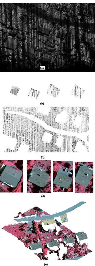
Figure 1. This figure shows the process of the proposal for this research study. Figure (1a) shows a point clouds from an urban area. Figure (1b) shows the extracted of four building in this area form the point clouds, and Figure (1c) shows the bare point clouds after subtracting all extracted object from the point clouds. Figure (1d) shows extracted buildings from the image after transforming and registering extracted building from the point clouds on the image. Figure (1e) shows an isometric view from reconstruction of the 3D model after transforming and registering extracted object from the image on the 3D model space or DTM developed from the point clouds.
The first operator has been developed based on curvature ( ) and signed curvature ( ) of the terrain at point p. The curvature of a surface at point p is:
) = ′ ) (Eq. 1)
Where ′ ) = ) ) is derivative of unit tangent vector,
) is curvature of surface at point p, ) is the unit normal vector. The signed curvature ) indicates the direction in which the unit tangent vector rotate, as a function of parameter along the curve. Negative singe indicates the rotation is clockwise, and positive singe indicates rotation is counterclockwise. With extension of above equation in a 3D Cartesian space, the curvature will be:
= ′′ ′ ′′ ′) ′′ ′ ′′ ′) ′′ ′ ′′ ′)
Where the prime and double prime denote to the first and the second derivatives. According to the above equation we can analyse and then extract an object from a point clouds data. The algorithm for extracting an object from the point clouds will be compare the magnitude and the singe of the curvature at the quadratic form as expressed in the following (Taubin 1995):
) = ! !!!" (Eq. 3)
Firstly, no attempt was made in order to develop a template as a framework for detecting and extracting building from the point clouds in this study. Some studies assumed the buildings have a rectangular shape and mostly focused on detecting and extracting rectangular shapes from the images (Tupin and Roux 2003). We believe that there is no reason to assume all buildings have a rectangular shape. In generic term we logically accept that all buildings have a closed and regular geometric shape and most of buildings’ roof has an elevation greater than 2 meters from the ground, as well as edges of roofs in most cases remain at the one level. According to the above knowledge, the operator which was developed based on either equation 2 or equation 4 searches for buildings within a defined area. It has to be noted that when speaking about detecting and extracting buildings in this study, it means to detect and extract the roof of buildings. After extracting buildings from the point clouds, all detected buildings will be checked and corrected before transform and register on the image. Then the buildings will be converted to raster format and then transformed and registered on the image. For transformation, an initial and rough orientation will be carried out. Then the algorithm will extract the corresponding building from the image according to the geometric information were obtained from the point clouds and using feature-based matching approach. Then each extracted building from the image will transform and register on the 3D models, the parameters of orientations were computed individually for each object as Homainejad (2011a) explained.
2.2 Proposal for extracting trees
For extracting trees from the point clouds, the algorithm mostly focuses on the Laser Scanner facts. New generation of Airborne Laser Scanners are able to record up to four backscattered waveforms returned from trees. Each emitted signal after hit the tree will penetrate to the ground, and each time when the signal hit the tree’s branches a reflected waveform will return to the
Laser Scanner. Unlike the returned waveform from a surface which forms a trace of a straight line, the returned waveform from trees scatters in an area. Therefore, for extracting a tree, or group of trees a grid is designed. The size of each cell of the grid is equal to the size of Laser Scanner footprint. Then the origin of the grid and bearing of its main direction will be defined. The algorithm will search according to the equations 2 or 4 and above initialisation inside each cell for (i) checking the density of point clouds inside of each cell, (ii) testing the variation of the curvature between points. If algorithm recognises the variation of the curvature is changing inside of each cell and the density is different with a defined criterion, then it will recognise and extract trees.
2.3 Proposal for extracting roads
Extracting road requires following initialisation. At the beginning a number of points on the road will be captured for extracted road will be checked and corrected. Then the extracted roads will converted to raster data and will transform and register on the image for extracting the corresponding roads from the image. Finally, the extracted road from image will be transformed and registered on the 3D model.
2.4 Proposal for extracting crown land
Each object after extraction will be removed from the point clouds and finally after removing all extracted object a bare point clouds will be available. The bare point clouds will represent the crown land. In this case, the point clouds consists many gaps regarding to the extracted object that can be easily filled by different methods such as interpolation method, but it has to be aware sometimes the interpolation will fill an area reconstruction. The project focuses on reconstruction 3D model by using aerial image and Laser Scanner data. The test data set was acquired over Vaihingen in Germany. Three areas have been chosen for participants, nevertheless, each area has slightly different from two other areas, but each area includes building, road, and trees. Digital aerial images were acquired by Intergraph/ZI DMC camera with ground resolution of 8cm. Point clouds has been captured by Leica ALS50 system with point density of 4 pts/m2. In this paper the results from two
areas will be shown. The first area is in the centre of city with is characterized by dense development consisting of historic buildings having rather complex shapes; also the area includes trees. The second area includes multistorey buildings.
4. IMPLEMENTATION AND ANALYSIS
the process of detecting and extracting the corresponding objects from the image. Finally, the transforming and registering objects from the image on the 3D model is the another consideration in this research study.
4.1 Detecting and extracting buildings
For extracting objects from the point clouds data, a polygon was initially defined that enclosed the study area. Then an operator which was developed based on the Equation 2 or Equation 4 was applied on the polygon for extracting objects. Since the results of two operators are similar, only the result of the first operator will be discussed here. At the first step the operator was searching the buildings inside the polygon according to the knowledge that initially introduced. The following pre-knowledge have been initialised for the building extraction from the point clouds: (i) the elevation of building which usually more than 2 meters from ground, (ii) the edge of the roof which usually stays in one level, and (iii) the roof has a regular geometrical shape such as rectangular, pentagon, and so on. As mentioned earlier, no attempt was made to introduce a template to the operator for assisting in building detection and extraction. Usually, some studies focused on detecting and extracting buildings which have a rectangular shape. Basically, most of buildings have different shapes; however, their shapes are geometrical. According to the initial knowledge, the operator tested the all points inside the defined polygon against the knowledge and the mathematical modelling. The extracted building were saved in a database and then captured in the computer in a 3D space. Each building has a particular shape, and operator is able to detect and extract any buildings with any type of shape. Figure 2 shows the extracted buildings inside the study area in a 3D model. There are some issues in the process of buildings extraction. For example, in a few cases a large tree partially obstructed a building, and the operator will extract only a part of buildings which wasn’t covered by the tree. In this situation, the extracted building will be captured in a 3D CAD environment and the missed part will be estimated and then a correction approach will be implemented to fix and fill the missing part. Both extracted buildings and their profiles were checked for finding any missing part regarding to the obstructed by an object. The pre-controlling from the result shows the operator extracted the buildings precisely. The roof of some buildings had a very complex shape but the operator was able to extract all parts of the roof.
4.2 Detecting and extracting trees
For detecting and extracting trees from the point clouds data, a grid has been defined. The size of the cell of the grid is roughly equal to the size of the footprint of the Laser Scanner. The grid has been oriented with the point clouds. Then the operator searched the defined area for detecting and extracting trees according to the introduced knowledge. The knowledge was defined based on the behaviour of the returned waveform from the tree. Since the new Laser Scanners are able to record up to four returned waveforms of a transmitter signal from woods area, and also the returned waveforms scatter in the grid, the operator will assess the density of the point clouds in each cell of grid. If the operator recognises the density of points in a cell of grid is different with the defined density, then it will assess the curvature of surface for each point. In this case, the operator will recognise a tree from background, if the curvature is changing rapidly. It has to be noted that the operator is not able to recognise the type of a tree because this is beyond the scope of this study.
4.3 Detecting and extracting roads
In this step, the start, the end, the changing direction points, and the maximum and the minimum width of the road will be introduced to the operator as initial knowledge. Then operator will extract roads inside the defined area. Actually, an international standard available for road construction, but some roads and streets have own characteristics that they have to be initially considered for the road extraction. In most of cases, the variation of curvature along the cross section of the roads always is very smooth and when reaches the edge of the road the curvature will be changed rapidly. In this study the operator will extract the road according to the initial knowledge and operator will not stop when the curvature changed rapidly because the point clouds data includes running vehicles on the road as well as parked vehicles. These unwanted data will interfere the process of road detection and extraction. Therefore, it was decided to extract the road according to initialisation and later a cleanup process was implemented in order to omit unwanted data.
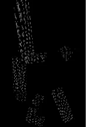
Figure 2. This is the result from extracting buildings inside the study area. As the figure shows each building has a specific shape.
Figure 3. This figure shows the profile of the buildings that shown in Figure 2. This figure shows how the curvature at edges of roof is changing rapidly.
4.4 Extracting crown land
existing status of the area. Therefore, a human supervision is required in this step.
4.5 Reverse registration
For assisting the process of the buildings detecting and extracting from the image, the extracted buildings from the point clouds were transformed and registered on the image. In this step the point clouds which are a vector format, will be converted to raster format (image) before registering. An initialisation and orientation is implemented earlier. The goals of the reverse registration are (i) to define the area for searching, (ii) to define the size of search window on the image, and (iii) to have a guide for segmenting and detecting the roof of building. A template-based matching is carried out to extract the buildings. The reverse registration improves the method of the object detecting and extracting. When a building has been detected, it will be tested and matched with the extracted one from the point clouds. The last part of the process seems confusing with the process of registering the extracted building from the image to the 3D model or the point clouds, but this part is very important part of the process because it assures the operator to extract only the roof of the corresponding and interested building.
4.6 Registering objects from image to the 3D model
This is a final step of the approach. In this step, the extracted objects from the image will transform and register on the 3D model developed from the point clouds as Homainejad (2011a) explained, and create a new 3D model. Basically two different processes will be implemented in this step. For both processes, a number of control points are initially defined on the image and the point clouds for orientation and initialisation. In the first process besides of initialisation and orientation, the algorithm will calculate the parameters of mapping for each individual pixel. The image always distorted while acquiring process and a correction always will be applied on the image for reducing the effects of the distortions. However, the distortions never removed from the image and always stay with image in some extension. If one looks the image as a whole, probably the remaining distortions will not be taken under consideration. However, if the image is split to the small areas the remaining distortions is very big issue and it is required the distortions to be removed perfectly. Therefore, the following equations were developed for mapping each individual pixel on the 3D model.
)*= + ),, - , -!, . , .!, / , /!) 0*= + 0,, - , -!, . , .!, / , /!)
(Eq. 5) Where )* and 0* are the coordinate of pixel on the 3D model, ), and 0, are the coordinate of control point, - , -! are angles of point i with two defined directions, / , /! are scale factors along X and Y directions, and . , .! are distances of point i to two defined base lines which will defined from following Equation.
. =+ ), , 0, , ),!, 0,!, )*, 0*) √∆)!+ ∆0!
(Eq. 6) Where ∆) = ), − ),! , and ∆0 = 0, − 0,! are
Scale Factors for each point in two directions which will be calculated separately. With applying above equation, each pixel from the images will be transformed on the 3D model precisely and all distortions will be removed.
In the second process, the image will be transformed and registered on the each extracted object from the point clouds. Since the algorithm will transform and register the only part of the image on its corresponding part on the point clouds which
has been already extracted, there is no requirement for the reverse registration in this step. The algorithm will define a search window on the image using information about the extracted data from the point clouds. The second process has been implemented for registering trees and the crown land from the image to the point clouds.
4.7 Analysing the result
In this research study, the point clouds was defined as the main and the only reference for checking and controlling the result, therefore, there is no attempt to correct and improve the point clouds data and it was assume that the corrections have been implemented in advance. For analysing the result, each point individually controlled visually and manually. For example it was checked that the corners of roofs are mapped in the correct location and they have had a correct elevation, or the tip of the building was mapped correctly and there was no any distortion remains. The analysing shows that the image was correctly mapped on the point clouds data. The standard deviation of points in X, Y, and Z directions is in the range of a fraction of centimetre with comparing the point clouds data. The focus of the analysis was on the 3D reconstruction of the buildings, since the roof of each building has special characteristics. Therefore, the roof of all buildings was individually checked in order to discover that the algorithm was able to precisely reconstruct the roof of a building in a 3D model and the 3D model shows all details. Figures 4, 5, 6, and 7 show the results after transforming and registering image on the point clouds. With study to these figures we realised that the algorithm was precisely developed a 3D model via registering an image on the point clouds and all details have been shown.
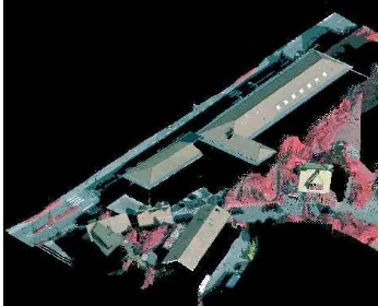
Figure 4. The figure shows the result from developing a 3D model for area 1.
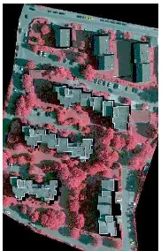
Figure 6. Figure shows 3D model of area 2 after applying the approach.
Figure 7. Figure shows the isometric view from the area 2.
5. CONCLUSION
A new approach for developing a 3D model has been mentioned. The approach extracts objects from the point clouds and registered on the image, for assisting in object detection and extraction from the image. This process is called reverse registration. The reverse registration enables the algorithm to detect and extract object from the image automatically. Then extracted objects from the image will be transformed to a 3D space and developed a 3D model. All pixels of the interested and extracted objects from the image will be converted to points and registered on a developed DTM from point clouds before transformed to the 3D space. For extracting object from point clouds, the curvature of surface of objects will be assessed. If the curvature is changing rapidly, the algorithm will recognise the object. In addition of assessment of the curvature, the algorithm will assess the extracted objects with a defined knowledge which are initially introduced to the algorithm. The evaluation of the extracted object confirms that the operator is very well able to detect and extract the objects from point clouds. The reverse registration improves to detect and extract the object from the image. Usually filtering and segmentation are common methods for extracting an object from the image, but reverse registration assures the process to extract the interested object correctly. Indeed the reverse registration is an integration process for object detection from the image. The application of the approach is very versatile and can be used in different purposes; for example, the approach can be used in planning and engineering, in analysing objects, in developing 3D GIS, in medical application, and emergency management.
6. REFERENCES
Bae, K.H., Belton, D., Lichti, D., 2009, A Closed-Form Expression of the Positional Uncertainty for 3D Point Clouds,
IEEE TRANSACTIONS ON PATTERN ANALYSIS AND MACHINE INTELLIGENCE, Vol 31, No 4, 577-590
Brahim, N., Gúeriot, D., Daniel, S., Solaiman, B., 2010, 3D reconstruction of underwater scenes using image sequences from acoustic camera, OCEANS IEEE, 1-8
Chen, Y.W., Kohatsu, T., 2007, 3D Image Reconstruction from Limited Projections by Simulated Annealing, Second International conference on Innovative Computing Information and Control, 456-456
Dammann, J., Redman, B., Ruff, W., 2006, 3D Image Reconstruction and Range-Doppler Tracking with Chirped AM Ladar Data, 35th Applied Imagery and Pattern Recognition Workshop, 4-4
Homainejad, A.S., 2011a, A novel approach for constructing a 3D model based on registering a mono image on a 3D model, applicable in Digital Earth, International Journal of Digital Earth
Homainejad, A.S., 2011b, Image registration on image splitting and pixel registration, Registration Quality-Towards Integration of Laser Scanning and Photogrammetry, Chief Editor: Petri Rönnholm, EuroSDR, Official Pblication No. 59, 79-102 Homainejad, A.S., 2010, An invented approach in image registration “new era in photogrammetry”, ISPRS TC VII Symposium – 100 Years ISPRS, Vol. XXXVIII, Part 7B, 299-303
Kirchhof, M., Jutzi, B., Stilla, U., 2008, Iterative processing of laser scanning data by full waveform analysis, ISPRS Journal of Photogrammetry & Remote Sensing 63, 99-114
Qian, L., 2010, Image 3D Reconstruction System for Indoor Environment Based on JAVA 3D, 2nd International Conference on Signal Processing Systems (ICSPS), V3-789 - V3-792
Silván-Cárdenas, J. L., Wang, L., 2006, A multi-resolution approach for filtering LiDAR altimetry data, ISPRS Journal of Photogrammetry & Remote Sensing, Vol 61, 11-22
Sportouche, H., Tupin, H., 2009, Leonard DENISE, Building Extraction and 3D Reconstruction in Urban Areas from High-Resolution Optical and SAR Imagery, Urban Remote Sensing Event, 1-11
Taubin, G., 1995, ESTIMATING THE TENSOR OF CURVATURE OF A SURFACE FROM A POLYHEDRAL APPROXIMATION, Proceeding of IEEE International Conference on Computer Vision, 902-907
Tupin, F., Roux, M., 2003, Detection of building outlines based on the fusion of SAR and optical features, ISPRS Journal of Photogrammetry & Remote Sensing 1267, 1-12
Wei, W., Guorong, W., Hua, C., 2009, 3D Reconstruction of a Femur Shaft using a Model and Two 2D X-ray Images, 4th
international conference on computer science and education, ICCSE, 720-722
Zhang, Z.Y., Tsui, H. T., 1998, 3D Reconstruction from a Single View of an Object and Its Image in a Plane Mirror, Fourteenth International Conference on Pattern Recognition, Vol 2, 1174-1176
ACKNOWLEGMENT