NEW METHOD FOR THE CALIBRATION OF MULTI-CAMERA MOBILE MAPPING
SYSTEMS
A. P. Kersting a, *, A. Habib a, J. Rau b
a
Department of Geomatics Engineering, University of Calgary, 2500 University Drive NW, T2N 1N4, Calgary, Canada
- (ana.kersting, ahabib)@ucalgary
b
Department of Geomatics, National Cheng Kung University, No.1 University Road, Tainan City 701, Taiwan -
[email protected]
Commission I, WG I/3
KEY WORDS: Adjustment, Calibration, GPS/INS, Multisensor, Mobile, Systems.
ABSTRACT:
Mobile Mapping Systems (MMS) allow for fast and cost-effective collection of geo-spatial information. Such systems integrate a set of imaging sensors and a position and orientation system (POS), which entails GPS and INS units. System calibration is a crucial process to ensure the attainment of the expected accuracy of such systems. It involves the calibration of the individual sensors as well as the calibration of the mounting parameters relating the system components. The mounting parameters of multi-camera MMS include two sets of relative orientation parameters (ROP): the lever arm offsets and the boresight angles relating the cameras and the IMU body frame and the ROP among the cameras (in the absence of GPS/INS data). In this paper, a novel single-step calibration method, which has the ability of estimating these two sets of ROP, is devised. Besides the ability to estimate the ROP among the cameras, the proposed method can use such parameters as prior information in the ISO procedure. The implemented procedure consists of an integrated sensor orientation (ISO) where the GPS/INS-derived position and orientation and the system mounting parameters are directly incorporated in the collinearity equations. The concept of modified collinearity equations has been used by few authors for single-camera systems. In this paper, a new modification to the collinearity equations for GPS/INS-assisted multi-camera systems is introduced. Experimental results using a real dataset demonstrate the feasibility of the proposed method.
* Corresponding author. This is useful to know for communication with the appropriate person in cases with more than one author.
1.INTRODUCTION
The use of integrated GPS/INS for direct sensor orientation has received increasing attention from the photogrammetric community in the past few years. Also, the utilization of larger number of cameras onboard the mapping platform (airborne/terrestrial), to obtain larger object space coverage, is a trend in modern photogrammetric mapping systems. Such systems, consisting of multi-sensors mounted on a mobile platform are usually referred to as Mobile Mapping Systems (MMS).
Although several benefits come from the use of navigation sensors (GPS/INS), the photogrammetric reconstruction process needs to be properly modified. One should note that for photogrammetric geo-referencing, the position and orientation of the camera coordinate system relative to the mapping reference frame is of interest. However, the position and orientation information derived from the integration of the GPS/INS observations would provide the position and orientation of the IMU body frame relative to the mapping frame. Therefore, besides the camera calibration parameters, the mounting parameters relating the system’s sensors must also be known. To determine such parameters a system calibration should be performed (El-Sheimy, 1996; Cramer and Stallmann, 2002; Pinto and Forlani, 2002; Honkavara, 2003; Habib el. al, 2010). For multi-camera systems, the mounting parameters encompass two sets of relative orientation parameters (ROP) (El-Sheimy, 1996): the ROP among the cameras as well as the lever-arm offsets and boresight angles between the cameras and the navigation sensors (i.e., the IMU body frame as the
navigation solution usually refers to its coordinate frame). The estimation of the lever-arm offsets and boresight angles between the cameras and the navigation sensors is necessary for GPS/INS-assisted multi-camera systems. Since the cameras and the navigation sensors are rigidly mounted on a platform, their geometric relationships are assumed to be invariant. The mounting parameters, which describe their spatial relationships, can be determined using either a two-step or single-step procedure. The two-step procedure for the estimation of the mounting parameters relating the cameras and the IMU body frame is based on comparing the cameras’ EOP, which are determined through a conventional bundle adjustment (indirect geo-referencing) procedure, with the GPS/INS-derived position and orientation information of the platform at the moments of exposure. Similarly, the estimation of the ROP among the cameras can be established by comparing the cameras’ EOP determined through an indirect geo-referencing procedure. Although such procedures are easy to implement, its reliability is highly dependent on the imaging configuration as well as the number and distribution of tie and control points since these factors control the accuracy of the estimated EOP. In the single-step procedure, the mounting parameters and additional parameters (e.g., camera self-calibration parameters) can be estimated in the bundle adjustment procedure (Cramer and Stallmann, 2002; Wegmann, 2002, Honkavaara et al., 2003; Honkavaara, 2004; Yuan, 2008). The commonly used single-step procedure in previous work consists of extending existing bundle adjustment procedures with additional observation equations (e.g., Cramer and Stallmann, 2002; Honkavaara et. al., 2003). Although for single-camera systems such approach is appropriate, when dealing with multi-camera systems,
dependent observation equations are introduced. One should note that any adjustment model is designed to deal with dependent/repeated observations. In the absence of GPS/INS data, constraint equations have been commonly used for multi-camera systems to enforce/estimate the invariant geometric relationship among the cameras (El-Sheimy, 1996; Lerma et. al, 2010; King, 1992). The drawback of incorporating these constraints to enforce consistent ROP among the cameras is the associated complicated procedure for doing that, e.g., extensive partial derivatives as well as manual formatting of the camera pairs to be utilized in the relative orientation constraints (ROC). These complexities are intensified as the number of cameras onboard gets larger.
In this paper, a new single-step procedure for the calibration of multi-camera photogrammetric systems is introduced. In the proposed method, the conventional collinearity equations are modified to incorporate not only the POS-based information but also the ROP among the cameras. When available, prior information on the ROP relating the cameras can be utilized in the calibration procedure. It is demonstrated that the same mathematical model can be utilized for the estimation of the ROP among the cameras in the absence of GPS/INS data.
2.PHOTOGRAMMETRIC SYSTEM CALIBRATION
METHOD
2.1 Conventional Collinearity Equations
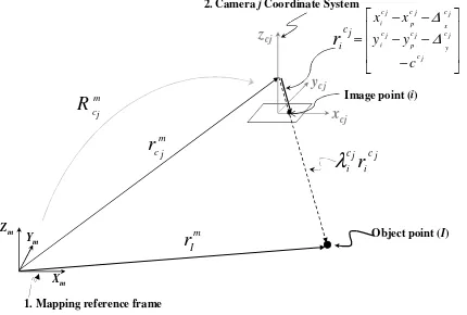
The underlying concept for the photogrammetric point positioning is based on the collinearity of the camera’s perspective center, the object point (I), and the corresponding image point (i). Such relationship is expressed through the collinearity equations. The conventional collinearity equations, in the form shown in Equation 1, can be derived through the summation of the vectors illustrated in Figure 1. Equation 1 can be rearranged to produce the final form of the conventional collinearity equations (Equation 2), by dividing the first two equations in Equation 1 by the third one after moving the image coordinates cj
i j c i
,
y
x
to the left side of the equations. Oneshould note that the scale factor
λ
cij is eliminated through the division process.Xm
Object point (I)
1. Mapping reference frame
Ym
Zm
2. Camera jCoordinate System
m
Figure 1. Involved parameters in the vector summation process to derive the conventional collinearity equations.
coordinate system to the jth camera perspective centre at a given time (t); point combination;
j
coordinates, principal distance and the distortions associated with the jth camera.
The conventional collinearity equations are utilized as the point positioning mathematical model in the bundle adjustment procedure based on indirect geo-referencing. For GPS/INS-assisted photogrammetric systems, the POS-based information (the GPS/INS-derived position and orientation and the system mounting parameters) has to be incorporated in the bundle adjustment procedure. Such procedure is denoted as Integrated Sensor Orientation (ISO). A commonly used procedure for doing that is to preserve the conventional collinearity equations while including additional observation equations. One should note that when dealing with multi-camera systems, dependent observation equations are introduced. An alternative approach for incorporating the POS-based information would be the utilization of modified collinearity equations, i.e., through the incorporation of the mounting parameters and the GPS/INS-derived position and orientation in the collinearity equations. Such concept has already been used by some authors in ISO procedures involving single-camera systems (Ellum, 2003; Pinto and Forlani, 2002; Habib et. al, 2010). In this paper, a new modification to the collinearity equations for multi-camera systems is proposed, which is described in the next subsection.
2.2 Modified Collinearity Equations for GPS/INS-Assisted
Multi-Camera Systems
In this research, modified collinearity equations, which incorporate not only the POS-based information for multi-camera systems but also the ROP among the multi-cameras, are introduced. More specifically, a point positioning mathematical model for GPS/INS-assisted multi-camera systems that would also allow for the use of prior information on the ROP among the cameras in the system calibration is devised.
xb
2. IMU body frame
1. Mapping Reference Frame
3. Reference Camera Coordinate System
4. Camera jCoordinate System
cr
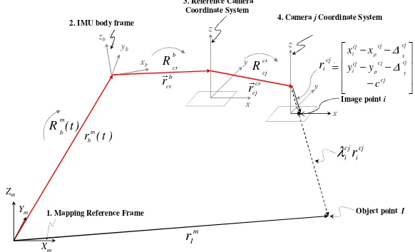
Figure 2. Involved parameters in the vector summation process to derive the modified collinearity equations for GPS/INS-assisted multi-camera systems.
The new point positioning mathematical model, presented in Equation 3, is derived through the summation of four conventional collinearity equations, one can note that the vector
)
R ). The final form of the modified collinearity
equations, after rearranging the terms in Equation 3 and dividing the first two equations by the third one is presented in Equations 4a and 4b.
+
coordinate system to the origin of the IMU coordinate system at a given time (t). This vector is derived from the GPS/INS integration procedure while considering the lever-arm offset between the phase centre of the GPS antenna and the IMU body frame;
)
origin of the IMU body frame to the reference camera (cr) perspective center, defined relative to the IMU body frame;
b r c
R : is the rotation matrix relating the IMU and the
reference camera coordinate systems;
r defined relative to the reference camera coordinate system;
camera and the jth camera coordinate systems.
j
2.3 Least Squares Adjustment (LSA) Implementation
The modified collinearity equations in the form in Equation 4 consist of the final form of the observation equations to be used in the LSA. One should note that the right side of Equations 4a and 4b entails not only the system parameters but also observations (e.g., GPS/INS-derived position and orientation information, ground coordinates of control points). In this work, instead of using the Gauss-Helmert model to deal with mixed unknowns and observations in the mathematical model, the ISO is implemented through a general LSA procedure. In the general LSA, all the involved quantities in the mathematical model can be treated either as unknowns, unknowns with prior information, or error free (constant) parameters. Initially, all the quantities on the right side of Equations 4a and 4b are treated as unknowns (camera IOP, ground coordinates of control points, ground coordinates of tie points, position and orientation of the IMU body frame, mounting parameters). In order to include prior information regarding any of these parameters, pseudo-observation equations can be added for such parameters. An example of pseudo-observation equation for adding prior information of the position of the IMU body frame relative to the mapping frame is shown in Equation 5.
) occupying the ith diagonal element, which is set as one.
2.4 Utilization of the Proposed System Calibration for the
Estimation of the ROP among the Cameras in the Absence of GPS/INS data
It can be demonstrated that the devised mathematical model can also be used for the estimation of the ROP among the cameras in the absence of GPS/INS data. The conceptual basis for doing that consists of placing a virtual IMU body frame in the same
b in Equation 6 should be regarded as the position and orientation of the reference Geo-referencing with ROC”, which is a single-step procedure for the estimation of the ROP among the cameras while enforcing the ROC.
3.EXPERIMENTAL RESULTS
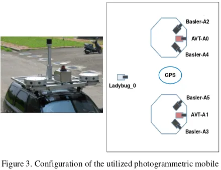
In this section, experimental results using a real dataset are presented to test the validity of the introduced method for the calibration of photogrammetric multi-camera systems. Figure 3 illustrates the terrestrial multi-camera mobile mapping system that was employed to collect the data utilized in the experiments. The system consists of seven cameras whose characteristics are described in Table 1. The camera calibration parameters were determined through an indoor camera calibration technique using the SMAC model and considered as constant in the system calibration procedure. A total of 70 surveyed points with accuracy of ±10cm were available in the experiment site. From those 70 points, 35 were used as control points in the system calibration while the remaining 35 were used for check point analysis.
GPS
Figure 3. Configuration of the utilized photogrammetric mobile mapping system.
Table 1. Characteristics of the utilized cameras.
Camera Nominal focal length (mm)
CCD array size (mm)
Pixel Size (µm)
First, the relative orientation parameters among the cameras have been estimated using the introduced indirect geo-referencing with ROC procedure, which utilizes the mathematical model in Equation 7. Table 1 reports the estimated ROP among the cameras and their standard deviations. In the reported results, camera “AVT-0” was taken as the reference camera (i.e., the position and the orientation of the platform refer to the position and orientation of camera “AVT-0”).
Table 2. Estimated lever-arm offsets and boresight angles w.r.t. camera “AVT-0” using the indirect geo-referencing with ROC
procedure. Camera “Basler-2”
0.88809 Camera “Basler-3”
-0.99457 Camera “Basler-4”
0.19413 Camera “Basler-5”
0.93879 Camera “Ladybug”
0.62387
deviation for the boresight angles ranges from ±7.4 to ±19.4 sec, while the lever-arm offsets have been estimated with precision of ~ ±1 mm. Also, the lever-arm offsets are very close to the physically measured values. The a-posteriori variance factor and the RMS analysis are also presented in Table 1, confirming the validity of the results.
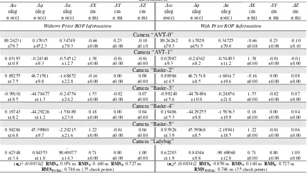
To test the validity of the proposed ISO procedure for the system calibration, which utilizes modified collinearity equations allowing for the use of prior ROP information, two experiments have been performed. In the first experiment, no prior information on the ROP among the cameras has been used. In the second run, the ROP among the cameras estimated using the introduced indirect geo-referencing with ROC procedure (presented in Table 2) have been utilized as prior information in the ISO. The results are reported in Table 3. The outcome from the proposed ISO procedure consists of the lever-arm and boresight angles of the reference camera (i.e., camera “AVT-0”) w.r.t. to the IMU body frame and the estimated ROP values (if no prior ROP information is used) or adjusted ROP values (if prior information is used). Here again, the estimated lever-arms are very close to the physically measured values. Table 3 also presents the a-posteriori variance factor and the RMS analysis for both experiments (with and without prior ROP information) demonstrating the validity of the method. We can note in Table 3 that very similar results are observed from the two experiments. In other words, the use of prior information on the ROP among the cameras hasn’t led to improvements in the estimated parameters. One should note that the proposed system calibration implicitly enforces the invariant geometric relationship among the cameras, and therefore, for a reasonable imaging configuration it is expected that the use of prior ROP information will not promote significant improvements. Larger improvements would take place in scenarios were a weak geometry and/or a poor tying among the images is present in the ISO, which is not the case of the utilized dataset in the experiments.
4.CONCLUSIONS AND RECOMMENDATIONS FOR
FUTURE WORK
In this paper, a new ISO procedure for calibration of GPS/INS-assisted multi-camera mobile mapping systems has been introduced. The proposed ISO utilizes a new point positioning mathematical model based on a novel modification to the collinearity equations for multi-camera systems. The introduced model allows for the incorporation of prior information on the ROP among the cameras. Also, it has been demonstrated that the same model can be used for the estimation of the ROP among the cameras in the absence of GPS/INS data. Experimental results using a real dataset have demonstrated the validity of the proposed method. For the utilized dataset in the experiments, the use of ROP prior information hasn’t led to significant improvements since a strong image configuration was available. Also, the same geometry/dataset has been used for the estimation of the ROP among the cameras. Future work will focus on more testing with real datasets under scenarios where the use of ROP prior information would play a more significant role.
ACKNOWLEDGEMENT
This work was supported by the Canadian GEOIDE NCE Network (SII-72) and the National Science and Engineering Council of Canada (Discovery Grant).
REFERENCES
Cramer, M. and D. Stallmann, 2002. System Calibration for Direct Georeferencing. ISPRS Comm. III Symposium ‘Photogrammetric Computer Vision’, Graz, Austria, 9-13 September 2002.
Ellum, C., 2003. The Development of a Backpack Mobile Mapping System. PhD Dissertation, Department of Geomatics Engineering, University of Calgary, Canada.
El-Sheimy, N., 1996. A Mobile Multi-Sensor System for GIS Applications in Urban Centers. International Archives of Photogrammetry and Remote Sensing, Vol. XXXI, pp. 95-100.
Habib, A., A. Kersting, and K. I. Bang, 2010. Comparative Analysis of Different Approaches for the Incorporation of Position and Orientation Information in Integrated Sensor Orientation Procedures. In: Proceedings of Canadian Geomatics Conference 2010 and ISPRS COM I Symposium, Calgary, Canada.
Honkavaara, E., 2003. Calibration Field Structures for GPS/IMU/Camera-system Calibration. The Photogrammetric Journal of Finland, 18(2): 3-15.
Honkavara, E., R. Ilves, and J. Jaakkola, 2003. Practical results of GPS/IMU camera system calibration. International Workshop, Theory, Technology and Realities of inertial/GPS Sensor Orientation, ISPRS WG I/5, Castelldefels, Spain, on CD-ROM, 10 pages.
Honkavaara, E., 2004. In-Flight Camera Calibration for Direct Georeferencing. International Archives of Photogrammetry, Remote Sensing and Spatial Information Sciences, Vol XXXV, Part 1, pp. 166-171.
King, B., 1992. Optimisation of Bundle Adjustments for Stereo Photography. International Archives of Photogrammetry and Remote Sensing, Vol. XXIX, pp. 168-173.
Lerma, J.L., S. Navarro, M. Cabrelles, and A.E. Seguí, 2010 Camera Calibration with Baseline Distance Constraints, The Photogrammetric Record, 25(130): 140-158.
Pinto L. and G. Forlani, 2002. A single step calibration procedure for IMU/GPS in aerial photogrammetry. In: International Archives of Photogrammetry and Remote Sensing, Vol. XXXIV, Part B3, pp. 210-213.
Yuan, X., 2008. A novel method of systematic error compensation for a position and orientation system. Progress in Nature Science, 18(8): 953–963.
Wegmann, H., 2002. Image Orientation by Combined (A)AT with GPS and IMU. ISPRS Com. I, Midterm Symposium, Integrated Remote Sensing at the Global, Regional, and Local Scale, Denver, U.S.A., 10-15 November 2002.
Table 3. System calibration results (i.e., estimated lever arm offset and boresight angles of the reference camera (i.e., camera “AVT-0”) w.r.t. to the IMU body frame and the estimated/adjusted values for the ROP among the cameras, standard deviations, a-posteriori
variance factor, and RMSE analysis – 35 check points) using 34GCP and the proposed ISO model without/with ROP prior information.
ω
(deg ± sec)
φ
(deg ± sec)
κ
(deg ± sec)
X (m ± m)
Y (m ± m)
Z (m ± m)
ω
(deg ±sec)
φ
(deg ± sec)
κ
(deg ±sec)
X (m ± m)
Y (m ± m)
Z (m ± m)
Without Prior ROP Information With Prior ROP Information
Camera “AVT-0”
89.26231 ±79.7
0.17015 ±452.3
0.34749 ±79.3
-0.66 ±0.08
0.23 ±0.08
-0.10 ±0.10
89.26262 ±79.3
0.17029 ±451.5
0.34725 ±79.0
-0.66 ±0.08
0.23 ±0.08
-0.10 ±0.10
Camera “AVT-1”
0.03193 ±10.9
-0.24340 ±9.3
-0.54512 ±12.7
1.38 ±0.00
-0.01 ±0.00
-0.01 ±0.00
0.02987 ±9.3
-0.24362 ±8.2
-0.54493 ±11.2
1.38 ±0.00
-0.01 ±0.00
-0.01 ±0.00
Camera “Basler-2”
0.89255 ±17.5
46.71581 ±9.8
-1.68852 ±22.8
-0.16 ±0.00
0.00 ±0.00
0.08 ±0.00
0.88986 ±14.5
46.71518 ±8.5
-1.68617 ±19.6
-0.16 ±0.00
0.00 ±0.00
0.08 ±0.00
Camera “Basler-3”
-0.99101 ±18.5
-44.78477 ±11.3
-0.24754 ±24.2
1.53 ±0.00
-0.02 ±0.00
0.07 ±0.00
-0.99240 ±15.6
-44.78496 ±10.0
-0.24856 ±21.0
1.53 ±0.00
-0.02 ±0.00
0.07 ±0.00
Camera “Basler-4”
0.19743 ±18.2
-44.29226 ±11.2
-1.58189 ±23.0
0.18 ±0.00
0.00 ±0.00
0.04 ±0.00
0.19486 ±15.3
-44.29255 ±9.8
-1.58363 ±19.9
0.18 ±0.00
0.00 ±0.00
0.04 ±0.00
Camera “Basler-5”
0.94286 ±16.8
45.39980 ±9.7
-2.20215 ±21.6
1.22 ±0.00
-0.01 ±0.00
0.06 ±0.00
0.93926 ±13.9
45.39968 ±8.5
-2.19941 ±18.5
1.22 ±0.00
-0.01 ±0.00
0.06 ±0.00
Camera “Ladybug”
0.62348 ±13.4
0.84353 ±11.0
-90.69077
±14.3
0.71 ±0.00
0.80 ±0.00
1.00 ±0.00
0.62203 ±11.9
0.84346 ±9.8
-90.69060 ±12.8
0.71 ±0.00
0.80 ±0.00
1.00 ±0.00
(σo)2: (0.0034)2 RMS
X: 0.051 m RMSY: 0.160 m RMSZ: 0.727 m RMSTOTAL: 0.746 m (35 check points)
(σo)2: (0.0034)2 RMS
X: 0.050 m RMSY: 0.160 m RMSZ: 0.727 m RMSTOTAL: 0.746 m (35 check points)