BACHELOR THESIS – ME 141502
ANALYSIS EVACUATION ROUTE FOR KM ZAHRO EXPRESS ON FIRE CONDITION USING AGENT – BASED MODELING AND FIRE DYNAMICS SIMULATION
Dioco Carlos Kristian Perdana
NRP. 4213 101 047
Supervisor :
Dr. Eng. Muhammad Badrus Zaman, S.T., M.T.
NIP. 1977 0802 2008 01 1007
Co Supervisor :
Dr. Eng. Trika Pitana, S.T., M.Sc.
NIP. 1976 0129 2001 12 1001
DOUBLE DEGREE PROGRAM OF
MARINE ENGINEERING DEPARTMENT
FACULTY OF MARINE TECHNOLOGY
INSTITUTE OF TECHNOLOGY SEPULUH NOPEMBER
SURABAYA
SKRIPSI – ME 141502
ANALISA RUTE EVAKUASI UNTUK KAPAL KM ZAHRO EXPRESS PADA
KONDISI KEBAKARAN MENGGUNAKAN
AGENT – BASED MODELING
DAN
FIRE DYNAMICS SIMULATION
Dioco Carlos Kristian Perdana
NRP. 4213 101 047
Dosen Pembimbing 1 :
Dr. Eng. Muhammad Badrus Zaman, S.T., M.T.
NIP. 1977 0802 2008 01 1007
Dosen Pembimbing 2 :
Dr. Eng. Trika Pitana, S.T., M.Sc.
NIP. 1976 0129 2001 12 1001
DOUBLE DEGREE PROGRAM OF
JURUSAN TEKNIK SISTEM PERKAPALAN
FAKULTAS TEKNOLOGI KELAUTAN
INSTITUT TEKNOLOGI SEPULUH NOPEMBER
SURABAYA
ii
iv
vi
vii
DECLARATION OF HONOR
I, who signed below hereby confirm that:
This final project report has written without any plagiarism act, and
confirm consciously that all the data, concepts, design, references, and
material in this report own by Reliability, Availability and Management
(RAMS) in Department of Marine Engineering ITS which are the product
of research study and reserve the right to use for further research study
and its development.
Name : Dioco Carlos Kristian Perdana
NRP : 4213 101 047
Bachelor Thesis Title:
Analysis Evacuation Route for KM Zahro
Express on Fire Condition using Agent-Based
Modeling and Fire Dynamics Simulator
Department:
Double Degree Program in Marine
Engineering
If there is plagiarism act in the future, I will fully responsible and receive
the penalty given by ITS according to the regulation applied.
Surabaya, 17 July 2017
viii
ix
ANALYSIS EVACUATION ROUTE FOR KM ZAHRO EXPRESS ON FIRE CONDITION USING AGENT – BASED MODELING AND FIRE DYNAMICS
SIMULATION
Name : Dioco Carlos Kristian Perdana
NRP : 4213 101 047
Department : Marine Engineering
Supervisor : Dr. Eng. Muhammad Badrus Zaman, S.T., M.T.
Co Supervisor : Dr. Eng. Trika Pitana, S.T., M.Sc.
ABSTRACT
Sefety is the thing that needs to be preferred by users of transport, passengers should also understand about safety procedures and evacuation procedures in the means of transport. There have been many accidents that happen in the world of transport, particularly in the shipping world, from 2010 to 2016 is no more than 50 accidents of ships in accordance with the cause recorded by KNKT (Komisi Nasional Keselamatan Transportasi).
On this research was discussed the evacuation time on the ship KM Zahro express that occurred earlier in the year 2017 in the Kepulauan Seribu, DKI Jakerta. Fire accident caused almost all the passengers died was caused due to the burning power source in the engine room.The issue will be discussed about the time of the evacuation and the danger of fires that interfere the process of evacuation.
The methods used are Agent Based Modeling and Simulation (ABMS) and Fire Dynamics Simulation (FDS) for modeling fire simulation. As well as using basic rules which refer to the International Maritime Organization (IMO).
Result of Evacuation simulation calculation on normal conditions that match at actual condition is 29,783 minutes (respon in not taken in this simulation), calculation results obtained from simulation of evacuation (Traveling Time) and at the count expanded feet according with the formula.
x
xi
ANALISA RUTE EVAKUASI DI KM ZAHRO EXPRESS PADA KONDISI
KEBAKARAN MENGGUNAKAN
AGENT-BASED MODELING
DANFIRE
DYNAMICS SIMULATOR
Nama : Dioco Carlos Kristian Perdana
NRP : 4213 1010 047
Jurusan : Teknik Sistem Perkapalan
Dosen Pembimbing I : Dr. Eng. Muhammad Badrus Zaman, S.T., M.T. Dosen Pembimbing II : Dr. Eng. Trika Pitana, S.T., M.Sc.
ABSTRAK
Keselamatan adalah hal utama yang perlu diperhatikan oleh pengguna transportasi, namun penumpang juga harus paham mengenai prosedur keselamatan dan prosedur evakuasi pada alat transportasi tersebut. Sudah banyak kecelakaan yang terjadi di dunia transportasi, khususnya di dunia pelayaran, dari tahun 2010 hingga 2016 sudah tercatat ada lebih dari 50 kecelakaan kapal sesuai dengan penyebabnya yang tercatat oleh KNKT.
Pada penelitian ini membahas mengenai waktu evakuasi pada kapal KM Zahro express yang terjadi pada awal tahun 2017 di kepulauan seribu. DKI Jakarta. Kebakaran kapal yang mengakibatkan hampir semua penumpang meninggal dunia itu diakibatkan karena terbakarnya sumber listrik pada engine room. Permasalahan yang akan dibahas adalah mengenai waktu evakuasi dan bahaya dari kebakaran yang menganggu proses evakuasi.
Metode yang digunakan adalah Agent Based Modeling and Simulation (ABMS) dan Fire Dynamics Simulation (FDS) untuk permodelan simulasi kebakaran. Serta mengunakan aturan dasar yang mengacu kepada International Maritime Organization (IMO).
Perhitungan hasil simulasi evakuasi pada kondisi normal atau siang hari yang sesuai pada kejadian sebenarnya adalah 29.783 menit (tidak mengambil data respon penumpang), perhitungan didapatkan dari hasil simulasi evakuasi (Traveling Time) dan di hitung susuai dengan rumus yang berlaku.
xii
xiii PREFACE
First of all, I would like to thank to Jesus Christ for the grace and bless so
the writer could finish the Final Project successfully. The title of Final
Project is:
“Analysis Evacuation Route for KM Zahro Express on Fire Condition using
Agent-Based Modeling and Fire Dynamics Simulator”
As the requirement to obtain a bachelor engineering degree on
Department of Marine Engineering Faculty of Marine Technology
Institute Technology Sepuluh Nopember.
Therefore, I would like to thank those who have helped in
completing my final project, among others:
1.
Jesus Christ who give all of His blessing and a chance to
complete this final project.
2.
For my parents Minggri Widiati and Kukuh Handani also my
Sister Jesica Ceren Kristiane Palevi for supporting me to
complete the study on Double Degree Marine Engineering.
3.
Mr. Dr. Eng. Muhammad Badrus Zaman, S.T., M.T. as the Head
of Marine Engineering Department
4.
Mr. Prof. Semin, S.T., M.T., Ph.D as the Secretary of Marine
Engineering Department
5.
Mr. Ir. Dwi Priyanta, M.SE as Secretary of Double Degree
Program in Marine Engineering Department who has giving
every necessary information to help finish the bachelor thesis.
6.
Mr. Sutopo Purwono Fitri, S.T., M.Eng., Ph.D as Author’s
Lecturer Advisor since first semester until eighth semester
7.
Mr. Dr. Eng. Muhammad Badrus Zaman, S.T., M.T. and Mr. Dr.
xiv
of RAMS Laboratory who has giving permission to do any
activities inside the lab and provides place during the working
of bachelor thesis.
9.
Komite Nasional Keselamatan Transportasi Indonesia, Mr. Aleik
Nurwayudi and Mr. Muslim for all of the information regarding
this final project.
10.
All of my beloved friends, especially Gishela Rahayu Suciati,
Muhammad Grizhaldo, Bramasto Aryo Bimo, Dirham Akbar
Aksara, Jericho Tuparev, Adhitya Wisnu Perdana Valdi Raka
Emirio, David Adi, Nizar Anwar Rizal, Puguh Purnomo.
11.
All staff and employees of RAMS laboratory that helped to get
more data and information for my final project.
xv
xvii
... v
DECLARATION OF HONOR ... vii
PREFACE ... xiii
Table of Contents ... xv
List of Table ... xviii
List of Figure ... xx
CHAPTER 1 ... 1
INTRODUCTION ... 1
1.1 Background ... 1
1.2 Statement Problems ... 2
1.3 Research Objectives ... 2
1.4 Research Benefits ... 2
1.5 Research Limitations ... 2
CHAPTER 2 ... 5
LITERATURE STUDY ... 5
2.1 The Safety Of Sea Transport ... 5
2.2 Evacuation Procedure ... 5
2.3 IMO Interm Guidelines ... 6
2.4 Performance Standard ... 7
2.5 Agent-Based Modeling and Simulation (ABMS) ... 10
2.5.1 Pathfinder ... 11
2.6 Pyrosim ... 11
2.6.1 Fire Dynamics Simulation (FDS) ... 12
2.7 Ship Evacuation Plan ... 13
2.8 Emergency Types ... 15
2.9 Response to Emergency ... 17
2.10 Safety Plan ... 18
2.11 Decreased Walking Speed ... 20
CHAPTER 3 ... 23
METHODOLOGY ... 23
2.1 Methodology Flow ... 23
3.2 Definition of Methodology Flow Chart ... 24
3.2.1 Statement of Problem ... 24
3.2.2 Literature Review ... 24
xviii
3.2.5 Make a New Evacuation Route ... 25 3.2.6 Fire Modeling ... 25 3.2.7 Evaluation of Result ... 25 3.2.8 Conclusions and Suggestion ... 25 CHAPTER 4 DATA ANALYSIS AND SIMULATION ... 27 4.1 Data of Ship ... 27
4.1.1 Main Data of Ship ... 27 4.1.2 General Arrangement of Ship ... 28 4.1.3 Engine and Fuel System ... 29 4.1.4 Ship Generator ... 29 4.1.5 Ship Evacuation Route ... 30
4.2 Time Calculation of Evacuation ... 31
4.2.1 Evacuation Modeling ... 32
4.3 Creating of Modeling & Simulation ... 34
4.3.1 Result of Evacuation Time Calculation ... 39
4.4 Fire Simulation Modeling ... 39
4.4.1 Creating Fire Simulation Modeling ... 40 4.4.2 Result of Fire Simulation Modeling ... 45 4.4.3 Analysis of Fire Simulation Modeling ... 46 CHAPTER 5 CONCLUSION AND SUGGESTION ... 49 5.1 Conclusion ... 49 5.2 Suggestion ... 50
Bibliography ... 51 ATTACHMENT 1 ... 53 ATTACHMENT 3 ... 65 ATTACHMENT 4 ... 73 ATTACHMENT 5 ... 81
List of Table
xix
xx
“This Page Intentionally Left Blank”
List of Figure
xxi
xxii
1 CHAPTER 1 INTRODUCTION
1.1 Background
Evacuation is a very important matter in a ship accident. Due to ship accident, evacuation is considered important to protect the crew and passengers in a ship. Things need to be done prior to prevent any casualties in a fire accident, is to make efficient evacuation route. Considered efficient when the evacuation processed in short amount of time, as to avoid any casualties in the accident. Data showed that 35% accident in a ship caused by fire (as show in figure 1.1). Causes of fire accident should be notice, like material used, workspace temperature and ventilation in engine room. It is important to note which area that will cause worst impact when fire occur, so while planning the evacuation route it can avoid those area. Because, it can harm the passengers while processing evacuation. [1] [2]
The important thing in the evacuation is the simple evacuation route and the route signs, so the passenger can understand easily the evacuation routes. Otherwise, there are other factors that must be considered, such as passengers characteristics, age, gender, and weight. It has an impact on the passenger walking speed that matter on the evacuation process. And other things to know is awareness time, the time when passengers can recognize the danger. Based on IMO calculation, length of corridors, doors and stairs own its safety factors related to crews speed of walking. Relation between the characteristics of the crew and the condition in a ship will affect in a pattern of evacuation.
The characteristics of the passenger, ship in fire conditions, this can affect the crew in the process of evacuation. Agent-Based Modeling and Simulation (ABMS) can provide models to the level of each individual behavior, as well as the adaptation process that allows any changes the nature of each individual can assist in modeling system, so the model will be similar to reality. [3]
Figure 1.1 Presentation of marine accidents by category (2010 -2016) [1] [4]1
1.2 Statement Problems
Based on the description above, problems of this thesis are:
1. How to determine the most efficient evacuation route?
2. How can fire affect the passenger while evacuation?
1.3 Research Objectives
The objectives of this research are:
1. Predict the effective time to evacuate passengers.
2. Determine how fire can affect the evacuation.
1.4 Research Benefits
The Benefits of this research are:
1. To help ship’s designer to design safety plan and efficient
evacuation route.
2. To optimize evacuations route to avoid the impact of fire.
1.5 Research Limitations
1. The limitations of this research is only to the cause and
3
5 CHAPTER 2 LITERATURE STUDY
2.1 The Safety Of Sea Transport
Safety is the most important factor for the passengers. Safety take precedence because of concerns the range of loss, if the safety factor is not met then it can result in a loss of time, material or may even cause fatalities. There is a source of accidents, include:
• Software (regulation, rule, procedure, etc.) that have not been
adequately
• Hardware (technology products means & infrastructures) which are already not worth
• Liveware (license, training, and culture) that are less supportive of
• Organoware (institutional, corporate organizations, crew guidance ) are not conducive.
2.2 Evacuation Procedure
Evacuation procedure is a thing that should be done when encountering danger and do the process of evacuation from the scene of danger to a place of safe refuge. The application of the proper evacuation procedures are also indispensable in order to anticipate the occurrence of the fire and turned upside down for the sake of the safety of all crew members who were in the boat. Based on International Maritime Organization (IMO).
Evacuation consists of two parts, the first directing passengers to the point of evacuation and then if the situation has allowed, lifeboats and life raft released a collapse to abandon ship. The first part is mainly taken care of by providing adequate lines on evacuation routes considering the number of passengers or crew.
Based on IMO Interm Guidelines to analyze passenger ship evacuation, we need to assumed some early calculation, so evacuation time analyzed based on real condition, and hopefully able to come close to real event. There are some assumptions of IMO MSC/Circ.1238, [5] such as:
a. Entire passenger and ship crew will start to evacuate in the same time, where on to another will not crash. Evacuation will start when the alarm sounded, and there is Awareness Time (A).
b. The entire passenger and ship crew will evacuate through main rescue tunnel. According to SOLAS regulation II-2/13, about establishment of evacuation route so passengers can quickly and safely heading to assembly point, the ship has to follow the terms :
• All passengers and crew will begin evacuation at the same time, and
will not hinder each other
• Passengers and crew will evacuate via the primary escape route
• Walking speed depends on the density of persons and the type of
escape facility, assuming that the flow is only in the direction of the escape route, and that there is no overtaking
• No passengers or crew have disabilities or medical conditions that
will severely hamper their ability to keep up with the flow
• Counter-flow is accounted for by a counter-flow factor
• Passenger load is assumed to be 100% (full load)
• Full availability of escape arrangements is considered
• People can move unhindered
• Effects of the ship’s motions, passengers’ age and disability,
restricted visibility due to smoke, etc., are accounted for in a safety factor. [5]
c. Based on IMO, there are some common term used in emergency, such
as :
• Evacuation, condition should be taken when the alarm to leave
the ship sounded.
• Mustering (gathering), planning to collect passenger in assembly
point, commonly the assembly point near the place where lifeboat or the rescue facilities is placed.
• Abandonment, where passenger leave the ship by using others
7
d. Common Terms used at evacuation according to IMO:
• Passenger load, maximum passenger number in ship.
• Crush condition, maximum density allowed in escape route, which is
3,5 p/m2
• Awareness time (A) is time needed by passenger to take action and
react in emergency.
• Travel Time (T) means time used by entire human to go out or travel
from exact place to the safer place or assembly point.
• Embarcation time (E) and launching time (L), time needed to transfer
all passenger to out of the ship.
• Awareness time (A) assumed 10 minutes in night case, and 5 minutes
in day case. [5]
2.4 Performance Standard
The following performance standards, should be complied with: Calculated evacuation time:
1.25 R + T + 2/3 (E + L) < n (1)………...….. (2.1)
E+ L < 30' (2)………...…… (2.2)
Figure 2.1 Performance Interim Guidelines[6]2
(1) 10' in case1 and case 3,5' in case 2 and case 4 (2) calculated as in appendix 1 to these Guidelines
(3) maximum 30' in compliance with SOLAS regulation III/21.1.4 (4) overlap time = 1/3 (E+L)
Conference. Performance standard (2) complies with SOLAS regulation III/21.1.4. Performance standard (3) Revised on 6 June 2016. [6]
Calculation of E + L should be calculated based on the results of full scale trials on similar ships and evacuation systems or data provided by the manufacturers, however, in this case, the method of calculation should be documented including the value of particular safety factor used. In case neither of the two methods can be used, E + L is assumed to be 30 min. [6]
Beside calculate evacuation time, we need take notice about safety route such as means escape. According to SOLAS Chapter II, Part D regulation 13, means escape is when entire person in ship can safely and quickly escape to embarcation deck lifeboat and life raft, here are the terms:
• There has to be a safe escape route.
• The escape route should be maintained to be safe and hurtle free.
• There should be extra help, which is as important, access, clear signing, and fulfilling design in emergency.
Parameters need to noticed in calculation:
a. Effective Width (We)
In order to accommodate lateral body sway and assure balance, persons moving through the escape routes maintain a clearance from walls and/or other fixed items (e.g. handrails, fixed seats, etc.). The effective width of any portion of an escape route is the clear width of that portion reduced by the sum of the clearances. [7]
b. Clear width
Clear width is:
• Measured off the handrail(s) for corridors and stairways
• The actual passage width of a door in its fully open position • The space between the fixed seats for aisles in public spaces
• The space between the most intruding portions of the seats (when unoccupied) in a row of seats in public spaces.
9
1. Density of Person (D)
Density of persons in an escape route is the number of persons (p) divided by the available escape route area pertinent to the space where the persons are originally located expressed in (p/m2)
2. Speed of persons (S)
The speed (m/s) of persons along the escape route depends on the density of persons and on the type of escape facility. Values for speed of persons are given in table 1.
3. Specific flow of persons (Fs)
Specific flow (persons/ms) is the number of evacuating persons past a point in the exit route per unit time per unit of effective width We of the
route involved. Values for Fe are given in table 1 for various values of
density and route characteristics.
4. Calculated flow of persons (Fc)
The calculated flow of persons (p/s) is the predicted number of persons passing a particular point in an escape route per unit time. It is obtained from:
Fc = Fs x We ……….……… (2.3)
5. Flow time (tF)
Flow time (s) is the total time needed for N persons to move past a point in the egress system, and is calculated as:
tF = N / Fc …………...……….. (2.4)
6. tstair= travel time(s) from the uppermost (or lowermost) deck to the
closest embarkation station.
7. tdeck= travel time(s) to move from the farthest point of the escape route
of a deck to the stairway.
8. Overall Time (tI)
The overall time to travel along an escape route to the assigned assembly station is:
tI = tF + tdeck + tstair ………. (2.5)
9. Travel time (T)
T = (γ+δ) tI ……….... (2.6)
where:
γ = Safety factor = 2.0
Agent-Based Modeling and Simulator (ABMS) is a modeling method that aims to model complex problems based on real cases. In this case the existing models can be used to plan and prepare an emergency if unwanted things happen. [3] [8]
• The ability to make the environment as the original state, such as chairs, walls, and other boundaries like the real world.
• The ability to simulate the position of fire when the building caught fire so it can make prevention.
• Ability to simulate several safety scenarios, such as a safety line, with no cost.
The purpose of the use Agent-Based Modeling and Simulator (ABMS) are:
• A modeling method suitable to model large systems and more
sophisticated modeling for other cases.
• Can be implemented to software with better levels of development.
• Used to resolve the problem in a real state
The Agent-Based Modeling and Simulator (ABMS) is designed to model a place that has a seat, path, exit door, humans, and others. This allows to model a lot of humans and fire on one place (as shown in figure 2.2). The purpose of this system is to simulate the evacuation of such a large crowd on the building, auditorium, stadium or concert hall. The system must able to show how agents interact each other in an emergency state, the fire situation, as well as space management can interfere the evacuation process, as well as agents who must avoid the fire as much as possible. The fire also represented as an agent who created and produced smoke. This system is used to plan and prepare an emergency case and offers the advantage of the evacuation process in the field, to minimalize the victims.
• An ability to describe the environment with chairs, street, exit, and the position of the agent.
• The ability to create adjustable multiple deployment process with fire and smoke production rate.
• Very useful simulation modeling technique, and there are some
11
• The advantages of using Agent-Based Modeling and Simulator to
model is flexible, describe the real conditions, and provide a way for the evacuation process to be implemented as quickly as possible without any of the victims. [3]
2.5.1 Pathfinder
Pathfinder is an emergency egress simulator that includes an integrated user interface and animated 3D results. Pathfinder allows you to evaluate evacuation models more quickly and produce more realistic graphics than with other simulators.
Pathfinder provides support for the import of AutoCAD format with DWG files. Pathfinder’s floor extraction tool makes it possible to quickly use the imported geometry to define the occupant walking space for the evacuation model.
Pathfinder supports two simulation modes. In Steering mode, agents proceed independently to their goal, while avoiding other occupants and obstacles. Door flow rates are not specified but result from the interaction of occupants with each other and with boundaries. In SFPE mode, agents use behaviors that follow SFPE guidelines, with density-dependent walking speeds and flow limits to doors.
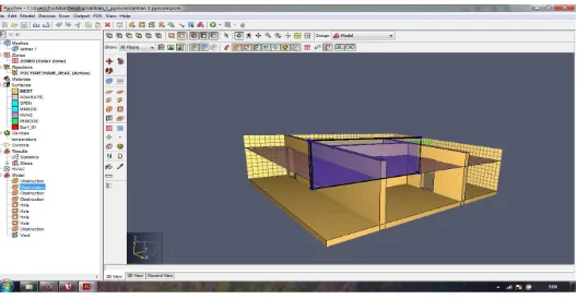
2.6 Pyrosim
PyroSim is a graphical user interface for the Fire Dynamics Simulator (FDS). FDS models can predict smoke, temperature, carbon monoxide, and other substances during fires. The results of these simulations have been used to ensure the safety of buildings before construction, evaluate safety options of existing buildings, reconstruct fires for post-accident investigation, and assist in firefighter training. [9] [10]
Institute of Standards and Technology (NIST). FDS simulates fire scenarios using computational fluid dynamics (CFD) optimized for low-speed, thermally-driven flow. This approach is very flexible and can be applied to fires ranging from stove-tops to oil storage tanks. It can also model situations that do not include a fire, such as ventilation in buildings. FDS and the Smokeview visualization program are both closely integrated into PyroSim. [9] [10]
2.6.1 Fire Dynamics Simulation (FDS)
FDS is a computer program that solves equations that describe the evolution of fire. It is a Fortran program that reads input parameters from a text file, computes a numerical solution to the governing equations, and writes user-specified output data to files. Smoke view is a companion program that reads FDS output files and produces animations on the computer screen. Smoke view has a simple menu-driven interface. FDS does not. However, there are various third-party programs that have been developed to generate the text file containing the input parameters needed by FDS. [11] [9]
Figure 2.3 Pyrosim Work Page
13
FDS can be used in order to create a model some of the following phenomena:
1. The transformation of heat and combustion products at low speeds
2. Transfer of convection and radiation between gas and surface
objects 3. Pyrolisys
4. Spread of flame and fire development
5. Detector and Sprinkler Activation
6. Fire Suppression with sprinkle
There are several major components used in resolving the problem of the FDS fire dynamics, namely:
2.6.1.1 Hydrodynamic Modeling
In this modeling FDS using the Navier-Stokes flow equations for low speed which involves the transformation of heat and smoke from fires that were affected by temperature changes. The calculations can use Direct Numerical Simulation (DNS) or Large Eddy Simulation (LES) that depends on the purpose of use and the resolution of the grid geometry..
2.6.1.2 Fire Modeling
The technique used is the fraction of the combustion mixture. This technique is based on the assumption that transport phenomena in conductive and radiative occurs on a large scale in addition to the physical processes that occur in small scale of time.
2.7 Ship Evacuation Plan
Evacuation procedure is an Ordinance to do when encountering a State of danger and the evacuation process from site of danger to a place of safe refuge. In addition to the completeness of the means of tackling the fire evacuation procedures, the application of the right is also indispensable in order to anticipate the occurrence of fire events for the sake of the safety of all crew members who were in the boat. [2]
must be qualified as follows:
• It can be easily set with the definition of a clear evacuation group and
travel schedules.
• Count with adequate levels of reability the time arrived to a gathering
place for the crew.
• Calculating and minimizing the time between the evacuation of the ship and its crew was the last moment out of the ship.
Therefore, in conducting the evacuation procedures should meet the following basic principles:
1. Evacuation Procedure Policy
In order to be effective, then there are a few things to note, namely the determination of the evacuation route, the election coordinator in charge of operations in each deck, rescue exercises by the entire crew when emergency conditions, install directions the way out and the information is pleased with the State of emergency at strategic locations in each deck.
2. Coordination of Displacements Movement in the process of Evacuation
The evacuation team coordination is indispensable to regulate the movement of the ship's crew to the Division of safety and emergency gathering place. There are some things that must be considered in the coordination of the evacuation team, namely the priority use of evacuation, lifeboat, life craft and several other safety tools.
3. Communication in the process of Evacuation
Perfection and accuracy of communication very or bills to make sure whether the crew is heading at this point in a safe gathering place.
4. Training Program
Training Program should be given to evacuation team namely the crew on how to rescue the passengers, performing communication between teams, crowd control, Division of safety, tools and techniques in fire-fighting.
5. Inspection and Evaluation
15
early.
2.8 Emergency Types
Vessel that does the activities can have problem caused by several factors such as climate, sailing route condition, vessel, human, and unpredictable things, which finally can caused damage to the vessel. [2] [12] [13]
The sailing disturbance sometimes can be handled, or need help from other parts, even can caused captain and crew to abandon the ship. Sailing disturbance based on situation can be classified according to the even itself, such as:
• Fire / Explosion
• Collision
• Shattered
• Pollution
• Leakage
• Man Over Board
Emergency can cause loss to every part, so we need to understand the condition, due to able to identify condition signs so it can be handled by captain and crew. [13]
1. Fire / Explosion
Fire in ship can happen in some vulnerable location such as engine room, cargo room, ship equipment storage, electrical installation and captain and crew accommodation room.
2. Collision
Emergency caused by ships crash, or with port or some material, will possible to damage in ship, casualties, oil spill in the sea, pollution and fire. Other situation is panic crew in the ship, which can slow down the evacuation.
3. Shattered
4. Pollution
Ocean pollution can happen by trash disposal or oil spilling in bunkering, waste disposal of tank ship cargo, leak tank waste caused by crash.
5. Leakage
Leakage in ship can caused by shatter, but can also cause by crushed or fire and ship outer plate damage by corrosion. The water come in quickly, while the ability to handle the leakage is limited, even the ship can be leaned, cause the situation hard to handle. This emergency become complicated, is the decision making is not fully supported by the entire crew.
6. Man Over Board
People fell to the sea is one accident that become emergency in term of rescue. Help given is not easily done, because very depend to the climate, ability of the helper and availability of facilities.
Emergency organization should be made in order to operate emergency. This organization in each situation aim to:
• Alarm Emergency state.
• Find and calculate the situation and possible danger.
• Organize power and tools.
There are four planning point need to be followed:
1. Command Center
Group that control activity under captain or senior crew coordination, equipped with intern and extern communication tools.
2. Emergency Party
Group under the senior officer that can calculate situation, reporting to commando center, suggest action need to be done.
3. Support Party
Supporting group under senior crew should be ready at every time to assist prior group, by the commando center command, and supply supporting assistance such as tools medical support, equipment, etc.
17
This group is under engineer or senior engineer support, supply assistance under commando center command. Main responsible is in engine room, and can help when needed.
2.9 Response to Emergency
Response on an emergency is based on an integrated pattern that is able to integrate activities or the emergency response effort in a fast, precise and controlled for the support of the relevant agencies and human resources as well as the facilities available [14]. By understanding this emergency response pattern can be obtained benefits:
1. Prevent (eliminating) the possibility of damage caused by the
widespread occurrence of emergency it is.
2. Minimize the damage of the material and the environment.
3. Can master the circumstances (under control).
To cope with emergencies required some anticipate that consists of:
a. Logging
In the face of any emergency is always decided upon actions that will be done to cope with such events, then for that to be done on logging the extent to which such emergencies can harm humans, ships and the environment as well as how to deal with it that is adapted to the available facilities and infrastructure.
Logging steps:
• The level of damage to the ship.
• Impaired the safety of the ship (stability).
• Human Safety.
• Charge Condition.
• The influence of damage to the environment.
• Possibility of harm against another vessel or pier.
b. Equipment (Rescue Facilities)
The salvation of the soul can be defined as actions or efforts that must be made in order for the crew or passengers of the vessel can safely abandon ship in the event of a hazard on a ship.
In the face of emergencies required means of this support. Such means include:
of an emergency.
• Fire alarm systems, fire hydrant and extinguisher.
• Health workers.
• Radio communication.
• Utilities (electricity and water)
• Life Guards.
Basic factors that influence the Self Rescue facilities are:
• Construction of the ship.
• The length of time to get out of the ship.
• The number and nature of activities of passengers.
• The place out.
• Control of the management of boat owners.
2.10 Safety Plan
A safety plan is a plan that is made to help ship owners avoid danger or potential danger to occured. The purpose of the annual safety is when there is an accident the parties can do an appropriate counter-measures.
With a safety equipment on the ship can prevent the occurrence of excess damage on the ship. For example, when there is a fire on the ship, with a safety plan when the fire broke out, the fire could quickly corrected with a sprinkle of an available hydrant or tubes. However, by the presence of a safety plan could not be ascertained that when fires break out on a steamer will soon be extinguished. It could just be the event of a fire, sprinkle the water squirt should work not working. It should be noted by ship owners. This incident could have happened because of an existing sensor is not working properly, or the placement of the security tools that do not fit in place, and could have been planning and safety installation not in accordance with existing procedures.
The primary purpose of the annual safety plan is:
1. To conduct studies and/or analysis on the impact of not fulfillment of standards and conditions of operation.
2. To get an alternative problem solving in terms of guaranteeing the level of operating
3. To estimate the effectiveness of each alternative solution of safety issues.
4. To make recommendations for changes or restrictions associated with
19
conditions of operation.
In the Safety Plan, the standard documents are matters of safety operation include, identification of the hazard, risk assessment and mitigation measures and conditions that must be met to maintain the level of safety steps, steps that must be done are:
a. Objectives, targets and programs. The intent was for what he did on this ship.
b. Safety plan and commitment what will be achieved.
c. Risk Assessment, aims to find a balance of resource allocation to all risk and control as well as mitigation. In the management of risk is
determined in advance the risk probability and severity
/consequences of risk.
d. Environmental impact and Aspect Identification (IADL) was also
created, if requested by the Owner/user of the service is the HSE Plan.
e. Mitigation is an action to eliminate the potential danger or reduces the probability or risk level. The frequency of the operations or activities are reduced, or taken action to reduce the level of the consequences of the risk is acceptable. While the last separation, is the action taken to isolate the effects of the risks or implement layered protection to reduce the level of risk. In mitigation, there are three defenses that may be applied:
• Technology
• Training
• Regulations/procedures
f. When these changes are made by placing the defenses, it must be ensured that such changes are not carrying the hazard along, and defenses are working as they should. Monitoring and reviewing is done to see if the defenses can really run so that the probability can be reduced.
g. Conclusion on the safety plan, there is some step that should be designed. A good safety plan will help to ensure the following:
• Assist fire with the layout and hazards associated with the ship
• Increase the speed of evacuation of the crew during a fire
considered are:
• Fire control plan
• Fire control booklets
• Live saving appliance plan
• Emergency situations
• Fire control and safety plan
• Safety sign location plan
• Cabin escape plan
2.11 Decreased Walking Speed
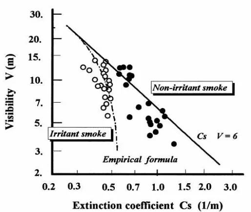
Smoke is the result of burning wood can affect the process of walking passengers and disrupting the evacuation process, the following graph between walking speed and the influence of smoke when the evacuation process.
Figure 2.5GraphicExtinction Coeficient against visibility Source: Studies on Human Behavior and Tenability in Fire Smoke
21
After determining the overall visibility of the value, then the next is determine the value of the Cs and then determine the value of gradations of walking speed. How to determine your walking speed and decrease in Cs namely the interpolation value graph with the specified visibility. After the value of the degradation speed obtained 0.8 then the walking speed at all agent converted to 0.8 speed running at normal conditions assuming the entire value of constant visibility
These two factors, namely the density of smoke and irritants affects the speed of walking. The selected type of smoke is irritant smoke that comes from the wood-burning results.
Figure 2.6Graphics Conversion speed against the influence of smoke Source: Studies on Human Behavior and Tenability in Fire Smoke
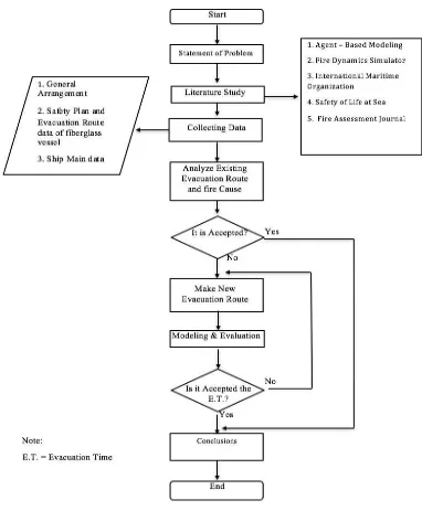
23 CHAPTER 3 METHODOLOGY 2.1 Methodology Flow
In the making of this final assignment, surely need structured process. That need to be planned, so in the future, the making will be more focused and easier. In this research methodology, will be explained each steps that will be done in the making of Final assignment about Analysis Evacuation Route using Agent - Based Modeling and Fire Dynamics Simulation. The stages are:
3.2.1 Statement of Problem
Problem formulation is the early stage of this thesis making. This is the most important stage, where the existing problem should be solve, so it deserve to be the material of this thesis. Finding the problem is done by digging the information about current problem. In this thesis, discussed problem that will be solved is Ship Fire Caused Analysis using Agent - Based Modeling.
3.2.2 Literature Review
After the problem is found, next stage is literature review. In this stage, the problem found and studied, so it can be clear what should be done in this thesis, in term to solve the problem. Literature review can be done by reading books, paper, journal or final assignment report related to the problem.
3.2.3 Fire Analysis
This analysis is done after literature study, that can be used to analyze the fire event. In this stage, the existing methods are used to analyze. In the end, we get the fire cause in the ship analysis.
3.2.4 Analyze Existing Evacuation Route
25
3.2.5 Make a New Evacuation Route
The next step, make the evacuation routes is proceed to the next stage. Because the evacuation routes to be used for modeling and simulation of fire evacuation. Make Evacuation Routes can be done by redrawing the General Arrangement and make a Safety Plan.
3.2.6 Fire Modeling
Fire modeling is done after making the new evacuation route by using existing data, the modeling aim to find out the real state of affairs in the case of a fire. In addition to that, fire modeling is also useful to know the location of the dangerous in the case of a fire. Fire modeling and simulation can be processed by using agent-based modelling and fire Dynamics Simulator
3.2.7 Evaluation of Result
The next is evaluate new evacuation route and fire modeling is already according to the standard or not. If according to standard then can proceed to the next stage and if it has not according to the standards then it should be through the previous stage again to produce results that comply with the standard.
3.2.8 Conclusions and Suggestion
27 CHAPTER 4
DATA ANALYSIS AND SIMULATION
4.1 Data of Ship
4.1.1 Main Data of Ship
KM Zahro Express (Tanda Selar: GT 106 No.6960/Bc, Call Sign YBA4008) is a traditional Indonesian-flagged passenger vessels which used as passenger transport from Muara Angke to Kepulauan Seribu. KMP. Zahro Express was built with Wooden construction on Pulau Harapan, Kepulauan Seribu by 2013. The ship is operated and owned by the individual. The wooden ship construction using iron wood/ulin to keel, laban wood to frames and mentru wood for strips bar bilge.
The Principal Dimension data about KM Zahro Express:
Name of Ship : KM Zahro Express
LoA (Length Over all) : 26.20 M
Lpp (Length Between Perpendicular) : 24.18 M
B (Breadth) : 6.00 M
D (Depth) : 1.64 M
GT (Gross Tonnage) : 106 GT
NT (Net Tonnage) : 32 NT
Flag : Indonesia
Type : Ro-Ro ( Roll on-Roll Off ) Ship
Year Build : 2013
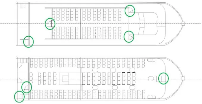
4.1.2 General Arrangement of Ship
KM Zahro Express is a wooden vessel with a single hull construction is built with traditional methods. Based on the safety certificate of passenger ship, the ship is approved to be able 285 of passengers and 5 persons crew.
KM Zahro Express has 2 decks which are divided into main deck and the upper deck. The decks are the spaces for passenger accommodation with seating facilities (as shown in figure 4.2). Passenger seating located on the main deck and the upper deck materials made of fiber reinforced plastic (FRP). On the topside there is also navigation control room or the Pavilion located at the bow.
KM Zahro Express has the engine room is located at the stern of ship, there are the main engine, engine generators, generator and fuel tank (right side) and the fresh water tank (as shown in figure 4.3). Access to the engine room through the sliding doors in the middle of the back wall of the engine room.
29
4.1.3 Engine and Fuel System
KM Zahro Express has 1 unit of diesel engine (NISSAN RH10). This machine is a type of V-line, 10 cylinders with engine power of 500 HP at 1800 rotations per minute. This machine is a land use type that have been reconditioned and modified for use on board.
The fuel tank made from FRP and mounted permanently on the right rear of the engine room with a capacity of 1 ton. Outlet pipes located in the fuel tank in the engine room.
4.1.4 Ship Generator
The ship's electrical power produced from 1 set of generators. According to information from the owner of the ship, specification of prime mover is an ISUZU engine with a 54 HP and an electric generator power is MARELLI brand 21 kVA or 16.8 kW, 3-phase and 4 wires that produces a 220/380 volt AC current with frequency 50 Hz. The prime mover and generator are a land use type engine.
Prime mover generator can be used with motor starter which include in the engine. Prime mover is turned on with the key that installed in the right of electric panel in engine room. To turned off the prime mover of generator, we can set the speed control lever by reposition the lever to the off-position.
The information from chief engineer in June 2016 while the ship sail, there was flare from generator several times that made short circuit in
generator. Next, chief engineer tried to operate the generator but it could not generate electrical power.
4.1.5 Ship Evacuation Route
KM Zahro Express has two main accommodation area, namely the main passenger deck located on the main deck with a capacity of 172 seats. There are also passenger accommodation decks on the upper deck with a total of 64 seats
Advanced examination against the real condition of the passenger accommodation decks, there main shows 214 seats and upper deck mounted 112 passenger seat with a total of 326 seats. Access for passengers to the vessel from the port is provided through the deck at the bow platform at the stern of the ship. The main deck accommodation room has 2 main access doors are available on either side of the bow with a width 77 cm and a single door access back to the kitchen and toilet area with approximately the same width.
Below is an overview of the evacuation line on the ship KMP. Zahro Express which already exist and which have been designed by the manufacturer of the ships
Due to a fire accident KM Zahro Express match reports from Basarnas. There are 24 died and 197 people survived. In accordance with the number of victims was found dead, as many as 20 passengers died found
31
are on the main deck accommodation spaces while the other 4 were found outside the ship.
Table 4.1 Victims Information [15]
Victims died Survivors Amount
Passengers 24 192 216
Crews - 5 5
Total Amount 24 197 221
Fires also resulted in severe damage on construction, from the bow section of the deck to the stern of the building destroyed by fire on board, space navigation, engine room and equipment was also destroyed by fire.
4.2 Time Calculation of Evacuation
Calculation of evacuation time of the KM Zahro Express refers to the rules of the IMO MSC/Circ. 1 1238 2007 which aims to :
•
Demonstrate the design of evacuation path, assambly point andnearest point with the safety equipment that is flexible for certain possibilities
.
Calculation of time evacuation of the KM Zahro Express using the IMO MSC.1/Circ.1238 Simplyfied method. More simplyfied method operates on mathematical calculations and analysis of the flow of movement of passengers in any room or a certain place. This method is more suitable when used to evaluate the process of evacuation ships with a relatively small ship. Because almost all the evacuation routes must be evaluated for each parts. Therefore it takes a long time to evaluate a relatively large-sized ships and had some of the evacuation.
In this modeling using calculation methods simplyfied. The calculation by the method has some characteristics simplyfied, namely:
• Each person represented as agent.
• The ability of each agent has parameters, the speed of walking. • Displacement of each of the agents was recorded.
• Each individual in the population has a variation of parameters.
• Each agent has the same percentage of the median in determining selection chose the evacuation.
4.2.1.1 Assumptions
Certainly requires a variety of assumptions to make modeling became more real or approaching the situation and conditions in the field. The following assumptions are used in the advanced methods of evacuation modeling.
• all passengers and crew will begin evacuation at the same time and
will not hinder each other
• initial walking speed depends on the density of persons, assuming that the flow is only in the direction of the escape route, and that there is no overtaking
• people can move unhindered
• counterflow is accounted for by a counterflow correction factor
• simplifications are accounted for in a correction factor and a safety factor
4.2.1.2 Performance Standard
IMO MSC.1/Circ.1238 determines that the standard evacuation time calculation methods simplify as follows:
1.25 R + T + 2/3 (E + L) < n ... (4.1) E+ L < 30’ ... (4.2)
where: T = Travel Time E = Embarkation Time L = Launching Time
n = Maximum time in the process of evacuation < 60’
33
Figure 4.6 Performance Standart Source : IMO MSC.1/Circ.1533 (1) 10' in case 1 and case 3, 5' in case 2 and case 4 (2) calculated as in appendix 1 to these Guidelines
(3) maximum 30' in compliance with SOLAS regulation III/21.1.4 (4) overlap time = 1/3 (E+L)
(5) values of n (min)
4.2.1.3 Identification of Passenger Density
Passenger density in certain areas are identified by passengers or crew with a density exceeding 4 p/m2 for a significant period of time. This level of passenger density will probably affect of evacuation simulation process overall. If density lasts for 10% of the total time of evacuation, it impacted significantly.
4.2.1.4 Parameters
IMO MSC.1/Circ. 1238 categorizes some parameters to facilitate simulation in modeling:
1. Category Geometrical
The primary discussion about the layout and placement of the evacuation route on the ship. The layout and placement of the evacuation route from the existing conditions in KMP. Zahro Express.
2. Category Population
passenger initial locations.
Characteristics of the walking speed of passengers based on gender and age range that is modeled in the uniform distribution of appropriate IMO MSC. Circ./1533, 2016. For walking speed passengers on the stairs go up or down is determined by the software itself, with the formula:
𝑉 𝑓𝑡 = &
',) ... (4.3)
The value of K correspond with the height of the stairs. As shown in the table 4.2,
Table 4.2 Value Convertion of K Height of Stairs
(Inch)
Width of Stairs
(Inch) K
7,5 10 1
7 11 1,08
6,5 12 1,16
6 13 1,23
Source : Technical Reference Pathfinder 2016
3. Category Environmental
Describe of Static and dynamic conditions of the ship. These parameters will influence the moving speed of persons.
4. Category Procedural
Assessment of the fourth case, the crew is assumed to follow the process of evacuation operations of embarkation point without exception.
4.3 Creating of Modeling & Simulation
35
Figure 4.7 Redraw General Arrangement KM Zahro Express
Every room is bounded on all sides by walls. Only one room can occupy the space given, so if one room stacked with another, the overlap will be reduced from the old room and given to a new one. Each room is also equipped with access doors so that passengers can get out of the room toward the evacuation point.
Figure 4.8 Creating layout KM Zahro Express
Figure 4.9 Creating stairs KM Zahro Express
After the layout completed, then the next step is to add the agent representing passengers and crew. Agent to be added has the characteristics of each. Height and width of shoulders assuming uniform distribution, altitude agent ranging between 1.58 – 1.71 meters for men and 1.47 – 1.6 metres for women, according to the statistics of the average height of people of Southeast Asia. While width of shoulder ranging between 34 – 48 centimeter for both men and women.
Figure 4.10 Insert Size of Shoulder Width
37
Figure 4.11 Creating Final Model
The image above is a picture of the final evacuation modeling standard in the case of evacuation. The model is ready to be run by producing traveling time.
After the model is complete and ready for running the simulation process can then immediately on the run. In this simulation process, the most important parameter is the behaviour of agents in the process of evacuation. There are two systems modeling simulation on the Pathfinder software, steering modes and SFPE mode.
Steering mode system attempt to imitation the behaviour and movements of agents. This system depend on the interaction of agents and evasion against the occurrence of collisions between agents.
SFPE system as explained on the SFPE Handbook of Fire Protection Engineering (Nelson and Mowrer, 2002) that controls the flow rate and the queue at the door. evacuation system specified is on the SFPE mode, because congestion arranged so that it does not exceed the initial assumption is 4 p/m2 for a significant period of time.
Figure 4.12 Dialog Box of Simulation
After the dialog box is running and all the agents evacuated, then the process will stop and it will automatically displayed a video simulation that generates time (traveling time) of evacuation.
Figure 4.13 Process of Simulation
39
Figure 4.14 Result of Simulation Case
On the graph can be analyzed that the ship KM Zahro Express takes at least 212,0 seconds (travel time) for passengers and crew out of the ship. In this case, the simulation was conducted on the time of day in accordance with the incident.
4.3.1 Result of Evacuation Time Calculation
After getting the value of traveling time, then the next step is to enter the value of traveling time that has been obtained to the standards of performance.
1.25 R + T + b (E + L) < n (E+L) ≤ 30’
Process simulation of evacuation (traveling time), for this case takes 3,533 minutes (including time delay). Evacuation time calculation as follows:
𝑒𝑣𝑎𝑐𝑢𝑎𝑡𝑖𝑜𝑛 𝑡𝑖𝑚𝑒 = 1.25 (5) + 3,533 + 2 30
3 𝑚𝑖𝑛𝑢𝑡𝑒
𝑒𝑣𝑎𝑐𝑢𝑎𝑡𝑖𝑜𝑛 𝑡𝑖𝑚𝑒 = 29,783 𝑚𝑖𝑛𝑢𝑡𝑒
4.4 Fire Simulation Modeling
Pathfinder software and Pyrosim software with process as follows:
Table 4.3 The process of creating a fire simulation model
Software Autocad Pathfinder Pyrosim
Function
Create ship design on each deck of the
ship
Create the evacuation modeling
Create the fire modeling
Description
Model based on the General Plan of the
ship KMP. Zahroo Express
Produce a traveling time is later processed into the
total process of evacuation time
Create fire modeling from layouts drawn
on Autocad
4.4.1 Creating Fire Simulation Modeling
Creating fire simulation model is started by import a file into autocad to software pyrosim with dimensions of the actual ship and the only room that can be occupied by passengers or crew.
Figure 4.15 Importing Pictures From Autocad
41
Figure 4.16 Create holes for the Access stairs and Doors
This hole is used for an access point of fire and smoke from one room to another room. The hole can be either a door or stairs connecting each deck. This hole is determined in such a way appropriate scale are on the General plan.
Figure 4.17 Creating Fire Simulation Model Layout
Material Floor External Wall Internall Wall Upholstory
Description The material used as the floor
The material used on the external walls of
the ship
The material used on the internal walls of the ship parts in separating room
Furniture in the Ship
Composition Mentu Wood Mentu Wood and Fiber Glass
Mentu Wood and Fiber Glass
Metru Wood and Steel
Once all the material is already adjusted to the reality, the ship model added source of fire to simulate the occurrence of fires. The source of the fire placed on the position of fire begins, the position of a fire that occurred in the engine room or accurately sourced in the place of the laying of the accu and generator.
This modeling simulated assuming the burning material is located on the Engine Room with the kind of wood material. This material has burned and Heat Release Rate Per Area (HRRPA) of 50 kW/m2 with the width of the area burned was of 2.4 m2. The value of this HRRPA obtained from test results Laboraturium
The source of the fire to burn the material added by adding a vent on the location of the source of the fire. Then determine the dimensions according to your needs and provide a profile of the shape functions as a source of fire (burner). After determining the area of the source of the fire, and the value of HRRPA, then specify the source of the fire reaction to fire simulation while it lasted. Using wood reaction, details the composition as follows.
• Carbon atoms 45.0
• Hydrogen Atoms 6.2
• Oxygen Atoms 40.0
43
Figure 4.18 The Reaction Generated By The Source Of The Fire
Creation of Mesh on modeling fire serves to limit the fire affected areas in this model. On this restricted mesh modeling is a ship full of open and who are at the top of the ship. Open and functioning for the discharge of smoke or fire resulting in fire modelling so that the smoke from the fires don't get stuck on the limitations of the specified mesh.
Figure 4.19 Creating a Mesh
Pathfinder, then modeling fire must produce data in the form of a planar graph that can be read by software pathfinder. Modeling fire regulated so it can be read by software with a 3D Plot set up pathfinder Data. A 3D plot of the resulting Data must be expanded feet according to the specifications of pathfinder.
There are several ways to simulate the FDS (Fire Dynamic Simulation), by Application Under also called Under OS and Under DOS.
Simulation Under OS run with an app maker fire modeling software (Pyrosim). The downside of this OS Under simulation requires extra computer performance. The advantages of simulation Under this OS is more tactical in the process of running it, there is a parameter estimation of the time required and run simulations that are easy.
Simulation Under DOS to other options in the run process simulation of a fire. The simulation runs are relatively shorter than the simulations Under the OS. This is due to the process of the FDS (Fire Dynamic Simulation) runs on its own at the command prompt. But this simulation process difficult to run because it must understand in advance in operating command prompt (McGrattan. 2016).
45
4.4.2 Result of Fire Simulation Modeling
Results from simulations of fires is a graphic animations of the simulation, in addition also produces graphs of parameter that is already installed. Animated graphics also produce planar graphs that have been installed (slices). These slices will also be used as an object which combined to ease the evacuation simulation based on the results of a simulation of a fire that has been done.
Figure 4.21 Result of Fire Simulation Modeling
In Figure 4.21 which is a result of the fire modelling shows that the spread of the smoke that comes from the engine room may spread to the rest of the deck. The smoke spread can be analyzed with device movement and slice.
Figure 4.22 Result of Graph
From the graph above, can the analysis time and the amount of smoke on deck. It can be seen that in the 1800 minutes smoke levels produced in the relatively high place so disturbing in the evacuation process.
The analysis has been done conclude some points as follows:
• Process simulation is done for 1800 seconds do not produce a large fire, only produces smoke that allows agents to carry out performance disrupts the process of evacuation simulation
• The results of this simulation produces smoke that reaches throughout
the body of the ship because of the location of the access stairs connecting anter deck is at near the source of the fire.
4.4.3 Analysis of Fire Simulation Modeling
Modelling of fire have resulted can be integrated with external evacuation modeling. It can be easier to analyze the impact that resulted in a change of the evacuation time on a variation of such cases.
47
by burning kerosene. To limit the visible sign of a run, the following relationship can be presented in Cs. Walking speed is constant, but for the visibility of the Agency declined. Visibility or ability seen in smoke irritate dropped sharply on the smoke density exceeds a certain level. In smoke irritate with thick concentration, the eyes can not open for a long time and couldn't see the words on the signs of the evacuation. Even in this case, when the signs are so simple or familiar with the passengers or crew to be understood at a glance, the effect of irritating fumes may not cause problems to identify. Irritant smoke reduces visibility of the Agency, especially when there is the possibility for panic.
Figure 4.23 Relation between Evacuation Time and Fire Simulation
This chart shows number of occupants that can evacuated in the beginning of smoke caused by fire. In the beginning of fire, none of passenger notice the fire.
0 5 10 15 20 25 30
Occupants 0 76 125 154 176 198 221
Beginning of Fire
Smoke started covering stern
Smoke spread to the main deck
smoke filled the lower deck and parts of the upper deck
smoke begin to spread in the upper deck 0 30 60 90 120 150 180 210 Nu m b e r o f O cc u p a n ts
Time of Evacuation (Minute)
Time Evacuation
Occupants
49 CHAPTER 5
CONCLUSION AND SUGGESTION
5.1 Conclusion
Based on the analysis and simulation has been done with the standard at IMO, then the conclusions of this thesis are:
1. Characteristics of the ship's passengers and crew the associated walking
speed in each case is different. Walking speed reduction occurs when accidents or fires that affect the length of the evacuation process.
2. The evacuation process simulation at normal condition and fire
condition can use simulation based on Agent Based Modeling Simulation (ABMS) with the relevant condition corresponds to the case that actually happened. With the output time, ABMS are able to represent the total evacuation time theoretically. All the simulations performed meet the standarts International Maritime Organization (IMO), however there are several factor that can affect the evacuation process, a physical and mental readiness of the passengers in the evacuation proxess on conditions of fire or danger that requires all passengers abandon the ship.
3. Evacuation simulation calculation result in normal condition is 29.783 minutes, the simulation is done during the day and according to the actual conditions, in these simulation there were 216 passengers and 5 crews all can be evacuated.
4. On the process simulation of fire, during the 1800 seconds do not produce a large fire, but smoke produced can interfere with the performanceof the agency to carry out the evacuation process. So the evacuation process become too long. Beside the condition of ship to many goods results in the evacuation process in interrupted
5.
There were 24 passengers (20 People died cause fire and 4 People wereitems belonging which affect the evacuation line
5.2 Suggestion
After Analyzing the calculation time of the evacuation, the author give suggestion for the next research are :
1. Create a new evacuation route and easily understand by all passengers
and crew
51 Bibliography
[1] Komite Nasional Keselamatan Transportasi & PT. Trans Asia Consultants, "Kajian Analisis Trend Kecelakaan Transportasi Laut Tahun 2003 - 2008," p. 79, 2009.
[2] S. Umaiyah, "Analisa Penyebab Kebakaran pada Kapal - Kapal Penyeberangan Jarak Pendek dan Usulan Peningkatan Sistem Manajemen Keselamatannya," Program Studi Teknik Perkapalan, Departemen Teknik Mesin, Fakultas Teknik,
Universitas Indonesia, Depok 16424, 2015.
[3] C. M. Macal and M. J. North, "Agent-Based Modeling and Simulation," pp. 86-98, 2009.
[4] Komite Nasional Keselamatan Transportasi, "DATA INVESTIGASI KECELAKAAN PELAYARAN TAHUN 2010 – 2016," 25 November 2016. [5] International Maritime Organization, "Guidelines for Evacuation Analysis for
New and Existing Passanger Ships," 2007.
[6] International Maitime Organization, "GUIDELINES FOR EVACUATION
ANALYSIS FOR NEW AND EXISTING PASSENGER SHIPS," in MSC.1/Circ.1238 , 2016.
[7] International Maritime Organization, "Interim Guidelines for
![Figure 1.1 Presentation of marine accidents by category (2010 -2016) [1] [4]1](https://thumb-ap.123doks.com/thumbv2/123dok/1542376.2045837/28.516.91.454.88.277/figure-presentation-marine-accidents-category.webp)

![Figure 4.1 KM Zahro Express [18]](https://thumb-ap.123doks.com/thumbv2/123dok/1542376.2045837/53.516.135.417.178.344/figure-km-zahro-express.webp)
![Figure 4.2 General Arrangement of KM Zahro Express [15]](https://thumb-ap.123doks.com/thumbv2/123dok/1542376.2045837/54.516.142.412.184.374/figure-general-arrangement-km-zahro-express.webp)
![Figure 4.3 Engine Room Layout of KM Zahro Express [15]](https://thumb-ap.123doks.com/thumbv2/123dok/1542376.2045837/55.516.105.395.250.392/figure-engine-room-layout-km-zahro-express.webp)