123456789012345678901234567890121234567890123456 123456789012345678901234567890121234567890123456 123456789012345678901234567890121234567890123456 123456789012345678901234567890121234567890123456
1234567890123456789012345678901212345678901234567890123456789012123456789012345678901234567890121234 1234567890123456789012345678901212345678901234567890123456789012123456789012345678901234567890121234 1234567890123456789012345678901212345678901234567890123456789012123456789012345678901234567890121234 1234567890123456789012345678901212345678901234567890123456789012123456789012345678901234567890121234 1234567890123456789012345678901212345678901234567890123456789012123456789012345678901234567890121234 1234567890123456789012345678901212345678901234567890123456789012123456789012345678901234567890121234 1234567890123456789012345678901212345678901234567890123456789012123456789012345678901234567890121234
B
B
B
B
B
USINESS
USINESS
USINESS
USINESS
USINESS
P
P
P
P
P
ROCESS
ROCESS
ROCESS
ROCESS
ROCESS
T
T
T
T
T
RENDS
RENDS
RENDS
RENDS
RENDS
WHITEPAPER
September 2003
David S. Frankel David Frankel Consulting
Paul Harmon Business Process Trends
Jishnu Mukerji Hewlett Packard James Odell James Odell Associates
Martin Owen Popkin Software
Pete Rivitt Adaptive, Inc.
Mike Rosen M2VP Richard Mark Soley Object Management Group
Contents:
Introduction
The Zachman Framework The Model Driven Architecture Model Standardization MDA and Software Development
Mapping MDA to the Zachman Framework
Summary Footnotes
The Zachman Framework
and the OMG's
Model Driven Architecture
Introduction
As organizations, products, customers and technologies continue to change at an increasingly rapid rate, managers have sought overviews that will allow them to understand how everything within their organization fits together. The currently popular term for such an overview is an architecture. Some architectures – a data architecture, for example – provide overviews of a specific part of the overall organization. Increasingly, the term enterprise architecture refers to a set of architectures, which, taken together, provide a complete view of an organization.
The Zachman Framework is one popular way of conceptualizing how all of the more specific architectures that an organization might create can be integrated into a comprehensive picture. The Zachman Framework is an analytic model or classification scheme that organizes descriptive representations. It does not describe an implementation process and is independent of specific methodologies.
The Object Management Group’s Model Driven Architecture (MDA) is an approach to creating models, refining models, and generating code from models. The MDA approach also includes technology to facilitate the transport of models and code from one implementation to another, and may, in the future, include the ability to reverse engineering code into models. It is important to note that MDA does not define a specific development methodology. Instead, it is a generic approach that can be used with existing methodologies.
This paper describes how the OMG’s Model Driven Architecture can be mapped to the Zachman Framework. The aim is to illustrate what aspects of the Zachman Framework can be supported by architects, analysts and developers who use MDA.
The Zachman Framework
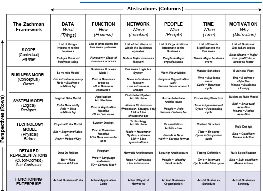
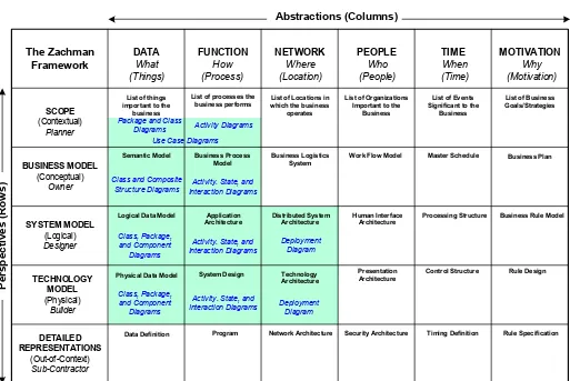
In the years since he wrote his original article, Zachman has worked to refine and elaborate his framework.[2] Figure 1 provides an overview of the current Zachman Framework.
Figure 1. The Zachman Enterprise Architecture Framework.
Zachman states that “The Framework for Enterprise Architecture is a two dimensional classification scheme for descriptive representations of an Enterprise.”[3]
The vertical dimension (the rows) describes the perspectives of those who use the models or descriptions contained in the cells. The top row represents the most generic perspective of an organization, while lower rows are successively more concrete. The bottom row represents a description of the actual data, code and people that make up the enterprise.
The perspectives, starting from the top of Figure 1, are:
SCOPE: (Contextual) The Planner’s Perspective. This describes the models, architectures and representations that provide the boundaries for the organization,
DATA
Entity = Class of business thing
List of processes the business performs
Function = Class of business process
List of Locations in which the business
operates
Note = Major business location
Time = Major business event
Ent = Business entity Rein = Business
relationship
Work Flow Model
People = Organization unit Work = Work product
Master Schedule
Time = System event Cycle = Processing I/O = Data elements/
sets
Presentation Architecture
People = User Work = Screen format
Control Structure I/O = Control block
Security Architecture
People = Identity Work = Job
Timing Definition
Time = Interrupt Cycle = Machine cycle
Rule Specification
Ent = Data entity Rein = Data
Actual Business Data Actual Physical Networks
and describe what senior executives must consider when they think about the organization and how it interacts with the world.
BUSINESS MODEL: (Conceptual) The Owner’s Perspective. This describes the models, architectures and descriptions used by the individuals who are the owners of the business process. They focus on the usage characteristics of the products.
SYSTEM MODEL: (Logical) The Designer’s Perspective. This describes the models, architectures and descriptions used by engineers, architects and those who mediate between what is desirable and what is technically possible.
TECHNOLOGY MODEL: (Physical) The Builder’s Perspective. This describes the models, architectures and descriptions used by technicians, engineers and contractors who design and create the actual product. The emphasis here is on constraints and what will actually be constructed.
DETAILED REPRESENTATIONS: (Out-of-Context Perspective) A Sub-Contractor’s Perspective. This describes the actual elements or parts that are included in, or make up, the final product (e.g. software components). Using the construction metaphor, Zachman refers to it as a sub-contractor’s perspective, and this makes sense to software developers when the design is implemented with modules or components acquired from others.
THE FUNCTIONING ENTERPRISE. The bottom row represents the actual deployed or running elements, data, and people of the organization. It isn’t a perspective, as such, but the “real world,” in all its complexity, that underlies all of the more or less abstract perspectives above it. (To simplify subsequent figures, we will drop the Function Enterprise row from other Zachman diagrams.)
The horizontal dimension of the framework (the columns) describes the types of abstractions that define each perspective. These abstractions are based on the widely used questions that people have historically asked when they sought understanding. The six questions or types of abstractions are as follows:
DATA: What is it made of? This focuses on the material composition of the product. In the case of software systems, it focuses on data. Zachman has proposed a simple, illustrative model for each of the columns. In this case, the model is: Thing—Relationship—Thing
FUNCTION: How does it work? This focuses on the functions or transformations of the product. The model is: Process—Input/Output—Process
NETWORK: Where are the elements located relative to one another? This focuses on the geometry or connectivity of the product. The model is: Node— Line—Node
TIME: When do things happen? This focuses on the life cycles, timing and schedules used to control activities. The model is: Event—Cycle—Event
MOTIVATION: Why do things happen? This focuses on goals, plans and rules that prescribe policies and ends that guide the organization. The model is: End— Means—End
Each cell describes an architecture, model, representation or description that an organization might document. Each of the cells in the framework is primitive and thus, each can be described or modeled independently. (Zachman refers to it as “normalized” with one fact in one place.) All of the cells on a given row make up a given perspective. All of the cells in a column are related to each other since they focus on the same type of elements.
Organizations may not keep all of the models described by the Enterprise Architecture Framework in one location. Some organizations do not formally define some of the cells, but, since all of the cells are logically necessary for a complete description of an organization, if they aren’t formally described, they are implicit in assumptions made by people in the organization.
The Object Management Group (OMG) was founded in 1989. It is a consortium of organizations that originally joined together to create standards and to encourage the use of object technology. Throughout the Nineties, the member companies that make up the OMG labored to create a set of standards, collectively known as the Object Management Architecture (OMA). The centerpiece of the OMA was CORBA (Common Object Request Broker Architecture), a middleware standard which defined how messages from diverse languages could be defined via a common intermediary language, the OMG’s Interface Definition Language (IDL), moved from client to target platforms via platform-independent protocols (e.g. IIOP), and then retranslated into the language of the target object or component. In another effort, the OMG formalized the Unified Modeling Language (UML), a modeling system that could be used to represent software designs.
For the past several years, the OMG has been moving beyond its roots in object standards. Its members, some 700 companies from throughout the world, are concerned with integrating and organizing all their software assets. Once they accepted that multiple middleware standards had established themselves in the market and that CORBA would always need to be combined with other middleware standards to create a complete solution at any large company, they began to think about more generic solutions to the integration problems they all faced. The Model Driven Architecture (MDA) represents a major effort to create the standards necessary to facilitate a comprehensive new approach to the creation, integration, and maintenance of software assets.
The goal of MDA is to create an enterprise architecture modeling capability that analysts and developers can use to describe a company’s business and software assets. By creating the architecture with software tools, companies are in a position to generate specific applications to implement the architecture and to modify those applications as the organization’s needs change. In other words, MDA represents a
major step in the direction of a real-time enterprise in which managers can make changes in architectures that are subsequently represented in code.[4]
MDA is concerned with models and talks about them in two different ways. First it is concerned with techniques that assure that all models used in software development can be aligned with all others. This focus emphasizes the use of MOF and metamodels. MDA is also concerned with organizing models used in the software development process so that developers can move from abstract models to more concrete models. This focus emphasizes the use of Platform Independent Models (PIMs), Platform Specific Models (PSM), and so forth. We’ll consider, first, how MOF provides common modeling standards, and then how models can be organized to facilitate efficient and flexible software development.
Model Standardization
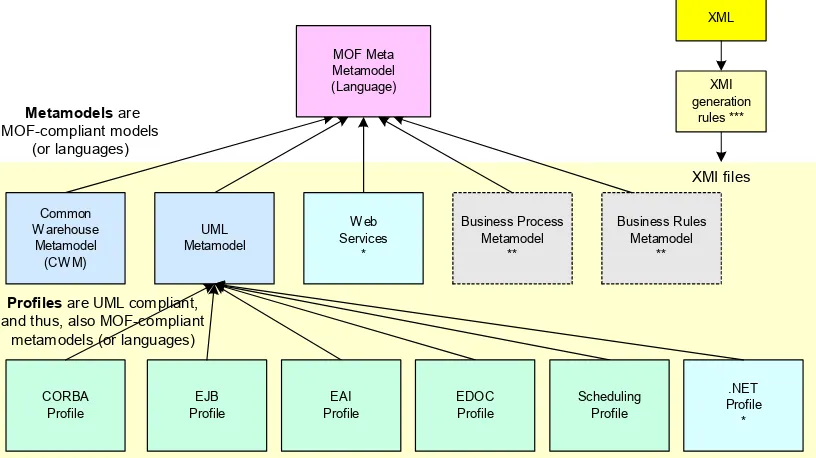
The Model Driven Architecture is supported by a number of models and standards. All MDA models are related because they are all based on a very abstract metamodel – the Meta Object Facility, or MOF. Every other model used in MDA is defined in terms of MOF constructs. In other words, every MDA model is MOF-compliant. This guarantees that all models used in the MDA system can communicate with every other MOF-compliant model. All of the different data representations in the OMG’s Common Warehouse Model (CWM) are MOF-compliant. Similarly, all of the diagrams supported by the Unified Modeling Language (UML) are MOF-compliant. (See Figure 2.)
UML supports extensions which are termed profiles. Profiles are MOF-compliant as a result of being extensions of UML. Profiles, in UML 2.0, are used to describe various functional uses of UML. Profiles are extensions to UML and are, themselves, MOF metamodels.[5]
Some MDA metamodels have been formally defined by the OMG. Some are still being developed by OMG task forces. In some cases, outside groups or vendors have developed MOF compliant metamodels. These non-OMG metamodels are MOF-compliant and can be used in MDA development, but they are not, as yet, official OMG standards.
The MDA models and profiles shown in Figure 2 are defined as follows, starting at the left of the second row:
The Common Warehouse Metamodel (CWM). The OMG’s formal model of metadata is used to manage data warehouses. Using CWM, developers can generate a number of more specific data models or formats, including relational tables, records or structures, OLAP, XML, multidimensional database designs, and so forth. This includes aspects which also have value outside the data warehousing environment such as data models, transformations, software deployment, and business nomenclature.
Component Diagrams, and Package Diagrams. In addition, the UML specification includes a facility that allows developers to establish constraints on various UML elements.
Web Services. Web Services is an example of a non-OMG metamodel developed to facilitate the development of MOF-compliant Web Service models.
The Business Process Definition Metamodel. This is an example of a metamodel that is still in the development phase. The OMG has called for proposals for a MOF-compliant metamodel for business processes. Such a metamodel would be independent of specific process definition languages and would allow MOF models to interface with languages like WSBPEL and notations like BPMN.
Business Semantics for Business Rules. Another example of a metamodel in development is an RFP for a MOF Metamodel for capturing business rules in business terms, and the definition and semantics of those terms in business vocabularies. In fact, there will be two specifications: a more generic standard for business rules, and a more specific one for production rules that are actually used by rule engines.
Business Rules Metamodel
**
Metamodels are MOF-compliant models
(or languages)
XMI files
XML
Common Warehouse Metamodel (CWM)
XMI generation
rules ***
Profiles are UML compliant, and thus, also MOF-compliant
metamodels (or languages)
MOF Meta Metamodel (Language)
UML Metamodel
Business Process Metamodel
**
.NET Profile
* CORBA
Profile
* Web Services and the .NET Profile are examples of metamodels (or UML profiles) that have been developed by outside groups. They conform to MOF but are not, as yet official OMG standards.
** The Business Process Metamodel and the Business Rules Metamodel are examples of standards that are still being developed by OMG committees.
Web Services
*
EJB Profile
EAI Profile
Scheduling Profile
*** The OMG has created an MOF-XML mapping that makes it possible for any MOF compliant model to pass information to other MOF models by converting the information into the XML Metadata Interchange language (XMI) and placing the information in an XML file. In effect, an XMI document is a MOF XML document.
EDOC Profile
CORBA Profile. This metamodel defines how to use UML to create CORBA-specific models. The CORBA specification includes the definition of a CORBA component model that can be modeled in UML and used in application development.
EJB Profile. This metamodel defines how to use UML to create J2EE or EJB-specific models. Developed by the Java Community Process.
EAI Profile. (The UML Profile and Interchange Model for Enterprise Application Integration.) This metamodel defines how to use UML to model event-driven EAI solutions.
EDOC Profile. (The UML Profile for Enterprise Distributed Object Computing.) This metamodel defines how to use UML to model distributed enterprise systems and the aspects of the business that they support (business processes, entities, events, etc.). The EDOC standard includes a Java metamodel that defines how to create Java-specific models.
Scheduling Profile. (The UML Profile for Scheduling, Performance and Time.) This metamodel defines how to use UML to model temporal aspects of (primarily real-time) computer systems.
.NET Profile. Another example of a profile created by developers independent of the OMG. A .NET profile defines how to use UML to create .NET-specific models.
There are other MOF compliant metamodels and UML profiles in existence and in development. We have only focused on those that can best illustrate how MDA can be mapped to the Zachman Framework. MDA is a work in progress, and the OMG will continue to develop new MOF metamodels as new technologies, languages or modeling elements need to be defined so that they can be integrated with MDA.
XMI. The OMG’s XMI (XML Metadata Interchange) standard assures that any compliant model can be represented as an XML document and stored in a MOF-compliant database. Thus, in effect, an XMI document is a MOF XML document. The latest version of UML includes the ability to specify the behavior of models so that they can be converted directly to code. At the moment, there is no standard way to transform any MOF model to any other, but an OMG committee is working on standardizing transformations.
MDA and Software Development
MOF assures that all compliant metamodels share a common set of core assumptions and definitions. MDA, however, is primarily focused on organizing the development and maintenance of software resources. Thus, MDA also describes how models are used in the software development process.
could be classified two ways. It would be a model that complied with the UML metamodel, and if it was platform independent, it would be a PIM model. The former tells what modeling conventions are being used (UML) and the latter tells how the model functions in the development process.
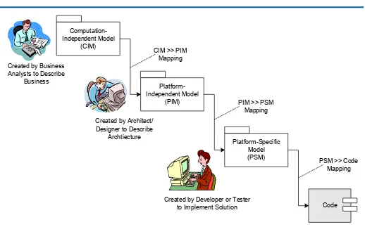
Figure 3 highlights the three different types of MDA models one uses in developing a system, and who is involved in using each. In this case we see that business analysts develop Computation Independent Models (CIM) that describes the business. Architects and designers subsequently create Platform Independent Models (PIM) to illustrate the organization’s architecture, without reference to any specific implementation. Later, developers and testers will use tools to generate specific software designs from the PIM architecture and then use their Platform-Specific Models (or designs) to generate code.
We won’t describe the MDA development process in any detail in this paper. Our goal here is simply to understand how MDA can be used to capture and use the types of information defined by the Zachman Framework.
The Zachman Framework wasn’t created with any implementation technology in mind. Similarly, the OMG’s MDA wasn’t created with the Zachman Framework in mind. In fact, however, if the Zachman Framework describes all of the architectures, models, descriptions and representations that managers and developers need to
Computation-Independent Model
(CIM)
Platform-Independent Model
(PIM)
Code Platform-Specific
Model (PSM) Created by Business
Analysts to Describe Business
Created by Architect/ Designer to Describe
Archtiecture
Created by Developer or Tester to Implement Solution CIM >> PIM
Mapping
PIM >> PSM Mapping
PSM >> Code Mapping
keep track of, and the MDA approach is designed to support the creation and management of an enterprise architecture, then they ought to be closely related.
As is suggested in Figure 2 the OMG’s Model Driven Architecture uses a number of MOF-compliant metamodels (e.g. UML, CWM) and UML profiles to represent information about systems. In Figure 3 we saw how any of the metamodels or profiles could be used to create models that might be used in a software development process. When a model is used in development, we can classify it in terms of its function, as a Computation Independent Model (CIM), a Platform Independent Model (PIM), or a Platform Specific Model (PSM).
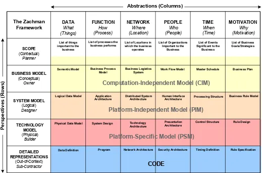
Figure 4 suggests how MDA models used in software development might map to the rows of the Zachman Framework.
Notice that we extended the MDA Computation-Independent Model up into the Scope or Contextual row of the Zachman Framework, but did not suggest that the entire Contextual row could be mapped to MDA CIM models. There is some difference on
DATA
List of processes the business performs
List of Locations in which the business
Semantic Model Work Flow Model Master Schedule Business Plan
Human Interface
Architecture Processing Structure
Business Rule Model
System Design Presentation Architecture
Control Structure Rule Design
Program Security Architecture Timing Definition Rule Specification Business Process
Data Definition Network Architecture Technology
s)
Computation-Independent Model (CIM)
Platform-Independent Model (PIM)
Platform-Specific Model (PSM)
CODE
Mapping MDA to the
Zachman Framework
this, depending on exactly what is included in the Contextual Row. In some cases, Zachman suggests they are lists or goals and these discrete items would not actually be included in MDA diagrams.
Next, we map the MDA metamodels and profiles to the Zachman Framework. There are several different, specific MDA standards and we didn’t want to make the resulting diagram too confusing so we have mapped the MOF-compliant metamodels in two separate figures. We’ll start by simply mapping UML to the Zachman Framework.
The OMG’s Unified Modeling Language is a set of core modeling elements that can be combined in different ways. Most developers think of UML in terms of diagrams that they use to represent models of different aspects, or states, of a software development process. There is no single way to use UML diagrams. Thus, some developers capture business requirements with use case diagrams and others represent business processes using UML activity diagrams. Class and sequence diagrams are often used for software analysis and design, and package and component diagrams are used to show specific designs and to indicate deployment plans.
In fact, each of these diagrams can be more or less complex depending on the elements the analyst uses. For example, one can create an activity diagram that shows activities and transitions between the activities. By the same token, one can create rows or swimlanes and label them with department names to show which department is responsible for what activity. In other words, a single activity diagram can incorporate elements that are described within different cells on the Zachman Framework. For example, the top left cell of the Zachman Framework (Scope/Data) focuses on lists of things important to the business. These could be represented by a very general class diagram where each class indicated a concept important to the business, or by a very general entity relationship diagram that suggested entities important to the business. As more details were added the diagram could serve as a business model or even a logical design. Similarly, one could create a very high-level activity diagram and simply label the swimlanes with departments to capture the list of organizations important to the business, or the business managers responsible for key parts of a major business process (Scope/People). An architect or analyst using UML would probably capture information from different Zachman cells using simpler UML diagrams and then add details to turn the initial diagram into a more complex diagram for some more specific purpose. This is similar to what a building contractor might do, creating one diagram to show the basic rooms in the house, and then using that diagram as the basis for a more complex diagram that would show electrical outlets, or the placement of furniture.
Figure 5 suggests how the core UML metamodel, with its various software analysis and design diagrams, might map to the Zachman Framework. The Framework could easily be addressed more fully by UML 2.0. For example, partitions of diagrams (e.g. swimlanes) could be used to represent any of the where, who, when, or why aspects of the Framework. OCL might be used to express the rule aspects in the Motivation column. Similarly, use case diagrams could be used to represent certain elements located in the People column. UML could also cover a good bit of the Time column in the guise of the new UML Scheduling Profile.
have indicated diagrams that might be used. In some cases, only simple versions of the diagrams might be created, while in others, more complex versions of the same diagram might be required. Different architects or analysts prefer different diagrams and might handle any given problem with still other diagrams that we have not shown, so the diagram names on Figure 6 are only suggestive.
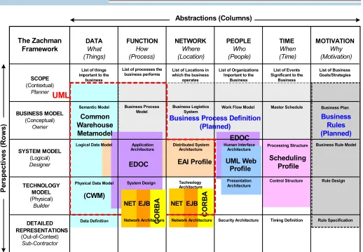
Figure 6 suggests how several other metamodels and UML profiles can be used to capture information from the various cells on the Zachman Enterprise Architecture Framework. The dashed line suggests the area in which UML diagrams might be used, as reflected in Figure 5. In Figure 6, we show two types of MDA standards. Standards that have already been adapted are shown in color while those that are currently being developed are illustrated with shades of gray.
Figure 6 illustrates how the various metamodels could be used to represent information described by the Zachman Framework. As you can see, most data aspects can be represented by models derived from the CWM metamodel. Data, Function and Network Systems integration issues can be modeled with the EAI profile. EDOC provides an efficient way to model some System, and most Technology, issues
DATA
List of processes the business performs
List of Locations in which the business
Semantic Model Work Flow Model Master Schedule Business Plan
Human Interface
Architecture Processing Structure
Business Rule Model
System Design Presentation Architecture
Control Structure Rule Design
Program Security Architecture Timing Definition Rule Specification Business Process
Data Definition Network Architecture Technology
associated with Functions and with human Interface issues. Some analysts will prefer a non-standard UML Web Profile for interface modeling. The new UML Scheduling Profile will probably prove popular with those seeking to model System, Technology, and some Detailed Representation of Time.
Profiles for .NET, EJB and CORBA can be used to represent the components used in Technology models and the relationships used in Networks. In some cases the Technology models can actually be used in Representational situations. Any of the profiles could be supplemented with UML diagrams, as needed.
Once the metamodel for Business Process Definition is established, a wide variety of process modeling notations and various proprietary workflow or process modeling metamodels will probably be mapped to the OMG Business Process Definition. That, in turn, will allow developers to prepare workflow or process diagrams and link them to other MDA models. Similarly, the upcoming Business Rules Metamodel will make it possible for a wide variety of proprietary business rule vendors to map their models to the OMG metamodel and thus achieve integration with MDA.
DATA
List of processes the business performs
List of Locations in which the business
Semantic Model Work Flow Model Master Schedule Business Plan
Human Interface
Architecture Processing Structure
Business Rule Model
System Design Presentation Architecture
Control Structure Rule Design
Security Architecture Timing Definition Rule Specification Business Process
Data Definition Network Architecture Technology
Figure 6 and the discussion above suggests how MDA-related standards can be used to support an Enterprise Architecture, as defined by John Zachman’s Framework. It suggests that those who have already spent time defining models according to the Zachman Framework categories should find it easy to apply MDA. There are, of course, many different ways to implement the Zachman Framework. None, however, offer the breadth and consistency of the MDA approach, which allows managers, architects and developers, from the Business Model perspective to the Detailed Representation perspective, to model and represent information and decisions in a consistent way, and then use the resulting framework, represented on an MDA tool or repository, to generate code and to subsequently maintain that architecture over the course of years.
[1] J.A.Zachman. “A Framework for Information Systems Architecture,” IBM Systems Journal, Vol. 26, No. 3, 1987. (The same article was reprinted in 1999 in a special double issue of the IBM Systems Journal that is easier to locate: Vol. 38, Nos 2&3, 1999.)
[2] Information on Zachman’s current work can be obtained from The Zachman Institute for Framework Advancement (ZIFA) www.zifa.com
[3] Zachman has recently prepared an electronic book, The Zachman Framework: A Primer for Enterprise Engineering and Manufacturing, which is available at
www.zachmaninternational.com
[4] For a detailed description of the elements of the MDA approach, see the OMG’s MDA Guide. (www.omg.org) Also see:
David S. Frankel. Model Driven Architecture: Applying MDA to Enterprise Computing (Wiley, 2003).
Anneke Kleppe, Jos Warmer and Wim Bast. MDA Explained: The Model Driven Architecture: Practice and Promise. (Addison-Wesley, 2003)
Michael Rosen. Understanding and Evaluating Modeling and MDA Tools. (Cutter Consortium Enterprise Architecture Report, Vol. 6, No. 5, 2003.)
Martin Owen. UML and the Enterprise. Paper presented at a conference and reproduced on the Popkin website: www.popkin.com.
[5] Information on the latest version of UML, version 2.0, is available on the OMG’s web site: www.omg.org.
Specifications for all other OMG metamodels or profiles described in this paper are documented on the OMG website: www.omg.org
The Zachman Framework for Enterprise ArchitectureTM is a trademark of John A. Zachman and Zachman International.
MDA®, Model Driven Architecture®, the MDA Logo, CORBA®, XMI® and IIOP® are registered trademarks of the Object Management Group. OMG™, Object Management Group™, the CORBA logo™, OMG Interface Definition Language (IDL)™, UML™,
Summary
Unified Modeling Language™, The UML Cube logo™, MOF™, CWM™ and IIOP™ are trademarks of the Object Management Group.
David S. Frankel is the CEO of David Frankel Consulting ([email protected])
Paul Harmon is the Executive Editor of Business Process Trends
Jishnu Mukerji is Senior Systems Architect, Strategy & Technology Office, Hewlett-Packard ([email protected])
James Odell is the CEO of James Odell Associates and co-chair of the OMG’s UML task force ([email protected])
Martin Owen is Consultancy Services Manager, European Headquarters, Popkin Software and Systems ([email protected])
Pete Rivett is Consulting Architect at Adaptive, Inc. ([email protected])
Michael Rosen is the CTO of M2VP ([email protected])