EXPERT SYSTEM IN DESIGN AUTOMATION FOR CUSTOMIZED
PRODUCT DEVELOPMENT - THREE DEGREE OF FREEDOM
VERTICAL CNC MILLING MACHINE
Agus Halim1), Jemmy Septiawan2), Didi Widya Utama3)
1,2,3)Dept. of Mechanical Engineering, Tarumanagara University, Jakarta 11440, Indonesia
e-mail: [email protected], [email protected], [email protected]
Abstract
New product has been emerging on the market faster and with better quality. There is a new emerging market, which is custom product development. The custom product development faces challenges such as time constraint and necessity for exploring customer view. In the concurrent engineering, more advanced CAD system is employed in the designing process such as virtual prototyping or AI. This article offers an alternative solution to enhance the design efficiency by using a formally defined expert system to automate designing process and generating 3D model, which is referred as design automation. One of the design automation being developed is the design of three degree of freedom vertical CNC milling machine. This system could boost the efficiency in designing and replaces the repetitive task in designing similar product.
Keywords: Design Automation, CNC Milling, Product Development
INTRODUCTION
New products have been launching on the market faster than its predecessor also with better function, durability, and cheaper. These constraints are the challenges facing in the engineering design and that means there is a shorter period of time in developing process. Thus put the designer under the great pressure to produce results as quickly as possible and often skip the analysis process in early design [1]. One of the many analysis method is Design for Manufacture and Assembly. This method could increase the productivity, efficiency and reduce the production cost if it were done in early stage.
According to Dieter, design is a process that pulls together something new to arrange existing things in a new way to satisfy a recognized need of society [2]. Nowadays, design is not just only for mass production but there is a demand for a customized design, a unique design and it is referred as custom product development. The customized product mainly equipped with the same equipment and offer the same feature but it is made to be tailor suited into the customer specification.
The problem in the custom product development is limited amount of time and meanwhile the need to explore customer perception on the customized product. However, in current computer aided design (CAD) system, there is virtual prototyping, which enables designer to provide design definition and a tailored, scenario-based environment to meet the expectation of the customer [3]. Virtual prototyping could greatly reduce resource and time invested. However, it consumed a considerable amount of time to generate a virtual prototype, which is dependent to skill of designer.
It is expected the next generation of design and manufacturing system is autonomous and intelligent so it can shorten the process or even skip the design process. Early application of artificial intelligent (AI) in design system is the system called
a new way of the CAD system which uses design automation based on this formally defined expert system with a study case on three degree of freedom CNC vertical milling machine.
A Computer Numerical Control (CNC) machine tool is a machine tool that uses a set of instruction to automatically position of cutting tool relative to workpiece. A milling machine is a type of machine tool defined by a rotating tool with cutting edges which is used to mechanically remove materials in forms of chips, as defined by [8]. Thus a three axis of CNC milling machine consist of some compulsory mechanical electrical components, which are linear motion guide, linear system positioning, actuators in each respective axis and cutting spindle as well as the controller of CNC systems.
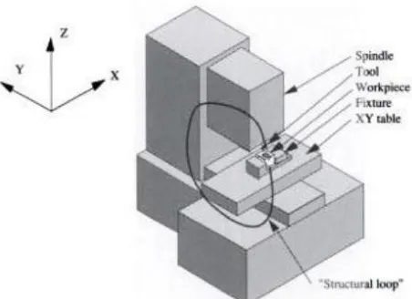
Machine structure is the essential factor in determining the performance of the machine tools itself since it is directly affecting the stiffness of the machine whether it is statically or dynamically. There are two common type of machine structure in the industrial, which are open frame and closed frame structures, described by Slocum [9]. Each kind of structures have their own pro and cons as well as application, which has been described by Wei Qin [10]. The structure of CNC milling machine in this article will adapt to the open frame structures, as shown as Figure 1.
Figure 1. Open frame machine tool structure vertical tool position [9]
LINEAR MOTION GUIDE
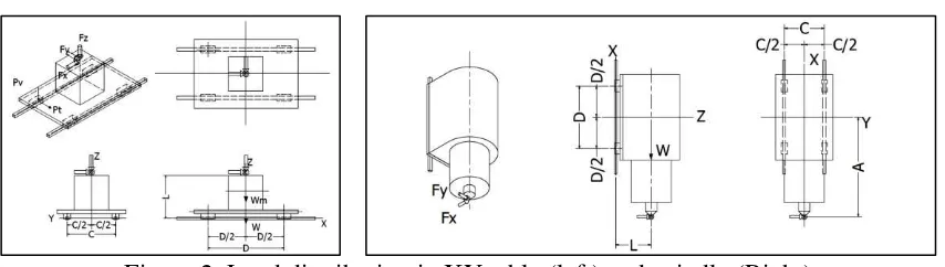
Figure 2. Load distribution in XY table (left) and spindle (Right)
Maximal load distribution is the sum of vertical load distribution ( ) and tangential load distribution ( ) of block, which is given by
( ) (2)
Where is the maximum distributed load of block, is the safety factor load for linear guideways, which the value is about 5 with operating condition in presence of impact and vibrations [11]. Vertical load distribution and tangential load distribution of table XY in Figure 2. are given by
(3)
(4)
Where is the system loads, is material weight loads, is axial cutting force, is x-axis cutting force and is y-axis cutting force. Vertical load distribution and tangential load distribution of spindle in Figure 2. are given by
(5)
(6)
Where is spindle and mounting weight loads.
LINEAR MOTION POSITIONING
Linear motion positioning used in this design of vertical CNC milling is ball screws, which consist of screw and nuts. Ball screw in vertical milling is used as a mechanical device that translates rotary motion into a linear motion as well as position the nut along the screw. The ball screw used in this milling machine is commercially available HIWIN ball screws and the selection of ball screw is based on the maximum dynamic load acting on the screw. The maximum dynamic load is given by
( ) (7)
Where as is the maximum dynamic load, is axial force of ball screw, is travel distance of ball screw in rotation, and is lead value of screw. Axial force of ball screw consist of axial operating load ( ) and preload force ( ), which is present to maintain the system precision. The axial operating load and preload force are given by
There are a lot of commercially available type of actuator could be used in this design of vertical CNC milling, which are servo motor and stepper motor. Each type of actuator has it pro and cons as described by Wei Qin for this design [10]. The actuator used is servo motor and the selection of servo motor for axis motor and spindle motor are based on the torque required to prevent from any malfunction or defect on cutting process. The torque required ( ) for spindle motor is obtained from cutting force calculation. The torque required for axis motor is obtained from equation given by
(10)
Where is torque require for axial load, is torque required for preload, and is torque required for accelerating work piece. Torque for axial load, preload and acceleration are given by linear guideways. Mechanical efficiency of the ball screw is about 0.9 to 0.95 and preload torque coefficient is about 0.1 to 0.3 [12]. Torque required for axis motor is dependent on the lead value of ball screw.
WORKFLOW OF THE SYSTEM
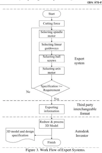
The work flow of this formally defined expert system in three degree axis of CNC milling machine begin with estimating the cutting forces. The estimation of cutting forces then are used to process a set of rules pre-defined for selecting main components such as linear guideways, ball screws and servo motor. The system then is to draft a selection of all components that will be awaiting the approval from the user. The approved components then will be used along with the other parameter to generate three dimension (3D) model. The whole process is illustrated in Figure 3.
Figure 3. Work Flow of Expert Systems.
STUDY CASE
The expert system will generate a 3D model vertical CNC milling machine based on a study case with following input or constraints:
1. Maximum length of work piece is . 2. Maximum width of work piece is . 3. Maximum height of work piece is . 4. Material of work piece is mild steel.
The acting working forces in a vertical milling machine consist of the work piece’s
The maximal cutting forces processed by the expert system from the cutting conditions of several milling operation in Table 1. are tabled in Table 2.
Table 2. Maximal cutting force of study case
Maximal specification Value following table based on the maximal cutting forces in Table 2. The component listed in draft by the expert system could be changed by the user to another specification provided by the database if necessary and the system will make sure that the specification of
changed component is still above the machine’s requirement.
RESULT AND DISCUSSION
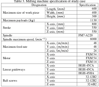
Table 3. Milling machine specification of study case
The draft of the selected component by the expert system from the input of this particular study case is presented in Table 3. The system will do the iteration for the components from the available database, thus the component that meet the minimum requirement of the system will be selected. The model generated by the system according to the components in Table 3. is presented in the Figure 5. The model generated is the general purpose models that are still need the verification and additional equipment if necessary.
Figure 4. 3D model of three axis CNC milling machine generated by expert system
The pre-drawn 3D model has about 879 parameters, ( ) and if the time needed to manually modify each parameter taken to manually modify each parameter is averagely 15 second, ( ) thus the time needed, ( ) to accustom this 3D model to design specification is about,
(14)
The subjective assumption of time needed for the expert system, ( ) to modify the parameter is about 5 minutes thus the overall subjectivity efficiency,( ) of the system is shown as following,
(15)
mentioning that this system could qualitatively increase the efficiency in the design process and delivering the design on schedule. The design generated only served as general purposes and the verification of design is needed. Possible future development of the system is to establish a framework that could simplify the design of the system so it could be used by more people and also a platform for sharing the design.
REFERENCES
[1] Geoffrey Boothryod, Peter Dewhurst, and Winston Knight, Product Design for Manufacture and Assembly. New York: Marcel Dekker, Inc., 2002.
[2] George E. Dieter, Engineering Design: A Material and Processing Approach, 3rd Edition.: Mc Graw Hill Publishing, 2000.
[3] Mitchell M. Tseng, Jianxin Jiao, and Jun Su Chuang, "Virtual Prototyping for customized product development," Integrated Manufactureing System, Vol. 9 Iss: 6, pp. 334-343, 1998.
[4] Michael G. Dryer, Margot Flowers, and Jack Hodges, "EDISON: an Engineering Design Invention System Operating Naively," Artiff Intell, pp. 36-44, 1986.
[5] Gabor Renner and Aniko Ekart, "Genetic Algorithm in Computer Aided Design,"
Computer Aided Design, vol. 35, no. 8, pp. 709-726, 2003.
[6] Jozsef Vancza, "Artificial Intelligence Support in Design: A Survey," in Integration of Process Knowledge into Design Support Systems. Netherland: Springer Netherland, 1999, pp. 57-66.
[7] Edgar A. Whitlye, "Two Approaches to Developing Expert Systems: A Consideration of Formal and Semi-formal Domains," AI & Society, vol. 5, no. 2, pp. 110 - 127, April - June 1991.
[8] Kevin Mark Noonan, A Unique Design for a Desktop Milling Machine. Sacramento: Department of Mechanical Engineering - California State University, 2012.
[9] Alexander H Slocum, Precision Machine Design.: Penintence Hall, 1992.
[10] Wei Qin, Design and Analysis of Small Scale Cost Effective CNC Milling Machine. Urbana: University of Illionis, 2013.
[11] HIWIN TECHNOLOGIES CORP., Linear Guideway - Technical Information, 2008.
[12] HIWIN TECHNOLOGIES CORP., HIWIN Ball Screw: Technical Information, 2010.