LAMPIRAN A
LAMPIRAN B
#include <conio.h>
#include <stdlib.h>
#include <stdio.h>
#include <dos.h>
#include <ctype.h>
/*
PA0-matikan 01
|
pin10-inframerah
PA1-kanan 02
|
pin11-mentok
PA2-naik 04
|
PA3-jepit 08
|
PA4-kiri 10
|
PA5-turun 20
|
PA6-buka 40
*/
main()
{
clrscr();
char pilihan,pilihan2;
int kiri,kanan,lebar,ttktgh,posisi,lengan,mm,gambar,mentok,batas1,batas2,status1,status2;
int portstatus,keadaan1,keadaan2,keadaan3,keadaan4,keadaan5,lenganmentok;
int tepat1,tepat2,jaka,jaki,gon,izon,goff,izoff,lengan2,lenganmentok1;
/*
periksa apa ada benda ditangan?
pin10
*/
outportb(0x37a,0x08);//reset
outportb(0x378,0x80);
delay(111);
outportb(0x37a,0x00);
delay(111);
outportb(0x37a,0x05);
delay(500);
outportb(0x378,0x01);
delay(500);
outportb(0x378,0x00);
portstatus=inportb(0x379);
keadaan1=portstatus&64;
//pin10(64)
if
(keadaan1==64)
{
delay(111);
outportb(0x378,0x80);
delay(111);
outportb(0x37a,0x00);
delay(111);
outportb(0x37a,0x05);
delay(111);
printf("\nturunkan benda");
outportb(0x378,0x20);//turunkan
delay(500);
outportb(0x378,0x00);
delay(500);
do
{
lenganmentok=inportb(0x379);
lenganmentok1=lenganmentok&128;
}
while(lenganmentok1!=128);
outportb(0x37a,0x08);//reset
outportb(0x378,0x80);
delay(111);
outportb(0x37a,0x00);
delay(111);
outportb(0x37a,0x05);
delay(500);
outportb(0x378,0x01);
delay(500);
outportb(0x378,0x00);
outportb(0x378,0x01);//off
delay(500);
outportb(0x378,0x00);
delay(500);
printf("\nnaik sedikit");
outportb(0x378,0x04);//naik sedikit
delay(500);
outportb(0x378,0x00);
do
{
lenganmentok=inportb(0x379);
lenganmentok1=lenganmentok&128;
}
outportb(0x378,0x80);
delay(111);
outportb(0x37a,0x00);
delay(111);
outportb(0x37a,0x05);
delay(500);
outportb(0x378,0x01);
delay(500);
outportb(0x378,0x00);
outportb(0x378,0x01);//off
delay(500);
printf("\nbuka lengan");
outportb(0x378,0x40);//buka
delay(500);
outportb(0x378,0x00);
delay(500);
do
{
lenganmentok=inportb(0x379);
lenganmentok1=lenganmentok&128;
}
while(lenganmentok1==0);
outportb(0x37a,0x08);//reset
outportb(0x378,0x80);
delay(111);
outportb(0x37a,0x00);
delay(111);
outportb(0x37a,0x05);
delay(500);
outportb(0x378,0x01);
delay(500);
outportb(0x378,0x00);
outportb(0x378,0x01);//off
delay(500);
outportb(0x378,0x00);
delay(500);
printf("\njepitsedikit");
outportb(0x378,0x08);//jepit sedikit
delay(500);
do
{
lenganmentok=inportb(0x379);
lenganmentok1=lenganmentok&128;
}
while(lenganmentok1==128);
outportb(0x37a,0x08);//reset
outportb(0x378,0x80);
delay(111);
outportb(0x37a,0x00);
delay(111);
outportb(0x37a,0x05);
delay(500);
outportb(0x378,0x01);
delay(500);
outportb(0x378,0x00);
outportb(0x378,0x01);//off
delay(500);
printf("\nangkat lengan kembali");
outportb(0x378,0x04);//atas
delay(500);
outportb(0x378,0x00);
delay(500);
do
{
lenganmentok=inportb(0x379);
lenganmentok1=lenganmentok&128;
}
while(lenganmentok1!=128);
outportb(0x37a,0x08);//reset
outportb(0x378,0x80);
delay(111);
outportb(0x37a,0x00);
delay(111);
outportb(0x37a,0x05);
delay(500);
outportb(0x378,0x01);
delay(500);
outportb(0x378,0x01);//off
delay(500);
outportb(0x378,0x00);
delay(500);
outportb(0x378,0x20);//turunsedikit
printf("\nturunsedikit");
delay(500);
outportb(0x378,0x00);
delay(500);
do
{
lenganmentok=inportb(0x379);
lenganmentok1=lenganmentok&128;
}
while(lenganmentok1==128);
outportb(0x37a,0x08);//reset
outportb(0x378,0x80);
delay(111);
outportb(0x37a,0x00);
delay(111);
outportb(0x37a,0x05);
delay(500);
outportb(0x378,0x01);
delay(500);
outportb(0x378,0x00);
outportb(0x378,0x01);//off
delay(500);
outportb(0x378,0x00);
delay(500);
}
clrscr();
/*tampilkan menu*/
outportb(0x37a,0x08);//reset
outportb(0x378,0x80);
delay(111);
outportb(0x37a,0x00);
delay(111);
outportb(0x37a,0x05);
delay(500);
outportb(0x378,0x01);
delay(500);
do
{
clrscr();
printf("\n=====================");
printf("\n1. Cari Benda");
printf("\n2. Keluar");
printf("\n=====================");
printf("\nPilihan Anda : ");
pilihan=getche();
switch(pilihan)
{
case '1' :
/*
posisikan lengan ke 0mm
- pin11
*/
lenganmentok=inportb(0x379);
lenganmentok1=lenganmentok&128;
if(lenganmentok1==128)
{
clrscr();
gotoxy(8,13);
clrscr();
printf("\n\nperiksa apakah ada yang salah dengan sistem mekanik");
delay(1000);
break;
gotoxy(1,1);
}
outportb(0x37a,0xe8);//nyalain bidirect dan adc
delay(100);
lengan=inportb(0x378);
if(lengan!=0)
printf("\nperiksa lengan.. tidak pada posisi awal..");
printf("\n\nGeser lengan ke kiri menuju posisi awal (0 mm)");
outportb(0x37a,0x08);//reset
outportb(0x378,0x80);
delay(111);
outportb(0x37a,0x00);
delay(111);
outportb(0x37a,0x05);
delay(500);
outportb(0x378,0x01);
delay(500);
delay(500);
printf("\ngeser ke kiri");
outportb(0x378,0x00);
delay(500);
outportb(0x37a,0xcd);//nyalakan adc
delay(111);
outportb(0x37a,0xed);//nyalakan bidirect
jaki=lengan-0;
gon=((jaki/5)*4);
izon=((jaki/5)*3);
izoff=((jaki/5)*2);
goff=(jaki/5);
lenganmentok1=inportb(0x379);
do
{
lenganmentok=inportb(0x379);
lenganmentok1=lenganmentok&128;
lengan=inportb(0x378);
if(lenganmentok1==128) //sudah mentok di kiri....
{
printf("\nmentok kiri....");
outportb(0x37a,0x08);//reset
outportb(0x378,0x80);
delay(111);
outportb(0x37a,0x00);
delay(111);
outportb(0x37a,0x05);
printf("\nmatikan..!");
delay(500);
outportb(0x378,0x01); //off
delay(500);
outportb(0x378,0x00);
delay(500);
printf("\ngeser ke kanan sedikit");
outportb(0x37a,0x08);//reset
outportb(0x378,0x80);
delay(111);
outportb(0x37a,0x00);
delay(111);
outportb(0x37a,0x05);
outportb(0x378,0x02); //kanan sedikit
delay(500);
do
{
lenganmentok=inportb(0x379);
lenganmentok1=lenganmentok&128;
}
while(lenganmentok1==128);
outportb(0x37a,0x08);//reset
outportb(0x378,0x80);
delay(111);
outportb(0x37a,0x00);
delay(111);
outportb(0x37a,0x05);
delay(500);
outportb(0x378,0x01);
delay(500);
outportb(0x378,0x01);//off
delay(500);
outportb(0x378,0x00);
delay(500);
lengan=0;
}
gotoxy(1,15);
printf("\n %d ",lengan);
if(lengan==gon)
{outportb(0x37a,0xef);printf("\ntambah kecepatan 1 ");}
if(lengan==izon)
{outportb(0x37a,0xeb);printf("\ntambah kecepatan 2 ");}
if(lengan==izoff)
{outportb(0x37a,0xef);printf("\nkurangi kecepatan 2");}
if(lengan==goff)
{outportb(0x37a,0xed);printf("\nkurangi kecepatan 1");}
}
while(lengan!=0);
outportb(0x37a,0x08);//reset
delay(111);
outportb(0x37a,0x80);
delay(111);
outportb(0x378,0x80);
delay(111);
outportb(0x37a,0x00);
delay(111);
delay(111);
printf("\nmatikan proses menuju titik awal");
outportb(0x378,0x01);//off
delay(500);
outportb(0x378,0x00);
delay(500);
printf("\nlengan sudah berada pada posisi awal");
delay(500);
printf("\nturunkan lengan untuk scan");
outportb(0x378,0x20);//turunkan
delay(500);
outportb(0x378,0x00);
delay(500);
do
{
lenganmentok=inportb(0x379);
lenganmentok1=lenganmentok&128;
}
while(lenganmentok1!=128);
outportb(0x37a,0x08);//reset
outportb(0x378,0x80);
delay(111);
outportb(0x37a,0x00);
delay(111);
outportb(0x37a,0x05);
delay(111);
outportb(0x378,0x01);//off
delay(500);
outportb(0x378,0x00);
delay(500);
printf("\nnaik sedikit");
outportb(0x37a,0x08);//reset
outportb(0x378,0x80);
delay(111);
outportb(0x37a,0x00);
delay(111);
outportb(0x37a,0x05);
delay(111);
outportb(0x378,0x04);//naik sedikit
delay(500);
outportb(0x378,0x00);
do
{
lenganmentok1=lenganmentok&128;
}
while(lenganmentok1==128);
outportb(0x37a,0x08);//reset
outportb(0x378,0x80);
delay(111);
outportb(0x37a,0x00);
delay(111);
outportb(0x37a,0x05);
delay(500);
outportb(0x378,0x01);
delay(500);
outportb(0x378,0x01);//off
delay(500);
printf("\ngerak ke kanan untuk mencari benda");
outportb(0x37a,0x08);//reset
outportb(0x378,0x80);
delay(111);
outportb(0x37a,0x00);
delay(111);
outportb(0x37a,0x05);
delay(111);
outportb(0x378,0x02);//gerak ke kanan untuk mencari benda
printf("\npelan saja agar akurat");
delay(500);
outportb(0x378,0x00);
delay(500);
clrscr();
// start
scan //
outportb(0x37a,0xcd); //nyalakan adc
delay(100);
outportb(0x37a,0xed); //nyalakan bidirect
delay(100);
status1=inportb(0x379);
do
{
status2=inportb(0x379);
batas1=inportb(0x378);
gotoxy(1,9);
lenganmentok=inportb(0x379);
lenganmentok1=lenganmentok&128;
if(lenganmentok1==128) //sudah mentok di kanan....
{
printf("\nmentok....!");
outportb(0x37a,0x08);//reset
outportb(0x378,0x80);
delay(111);
outportb(0x37a,0x00);
delay(111);
outportb(0x37a,0x05);
printf("\nmatikan..!");
delay(500);
outportb(0x378,0x01); //off
delay(500);
outportb(0x378,0x00);
delay(500);
status2=1;
}
}
while (status1==status2);
gotoxy(1,1);
clrscr();
printf("\nsisi pertama : %d",batas1);
status1=inportb(0x379);
do
{
status2=inportb(0x379);
batas2=inportb(0x378);
gotoxy(1,10);
printf(" %d ",batas2);
lenganmentok=inportb(0x379);
lenganmentok1=lenganmentok&128;
if(lenganmentok1==128) //sudah mentok di kanan....
{
printf("\nmentok....!");
outportb(0x37a,0x08);//reset
outportb(0x378,0x80);
delay(111);
outportb(0x37a,0x00);
delay(111);
printf("\nmatikan..!");
delay(500);
outportb(0x378,0x01); //off
delay(500);
outportb(0x378,0x00);
delay(500);
status2=1;
}
}
while(status1==status2);
gotoxy(1,2);
clrscr();
printf("\nsisi pertama : %d",batas1);
printf("\nsisi kedua : %d",batas2);
//printf("\njarak dari sebelah kanan : %d
milimeter",batas2); //tampilkan data..
lebar=batas2-batas1;
if(lebar<=0)
{
lebar=0;
outportb(0x37a,0x08);//reset
outportb(0x378,0x80);
delay(111);
outportb(0x37a,0x00);
delay(111);
outportb(0x37a,0x05);
delay(500);
outportb(0x378,0x01);
delay(500);
break;
}
printf("\nlebar objek adalah %d milimeter",lebar);
ttktgh=lebar/2;
//printf("\ntitik tengah objek berada pada posisi %d
milimeter",ttktgh);
posisi=batas1+ttktgh;
if(lebar<=0)
{
posisi=0;
}
printf("\nPosisi tengah benda berada pada %d
milimeter",posisi);
delay(111);
outportb(0x378,0x80);
delay(111);
outportb(0x37a,0x00);
delay(111);
outportb(0x37a,0x05);
delay(111);
printf("\nmatikan proses pencarian benda\ngerak ke kiri
menuju posisi tengah benda");
outportb(0x378,0x01); //matikan scan..
delay(500);
outportb(0x378,0x00);
delay(500);
outportb(0x378,0x10); //kiri
delay(500);
outportb(0x378,0x00);
delay(500);
outportb(0x378,0x10); //kiri
delay(500);
outportb(0x378,0x00);
delay(500);
outport(0x37a,0xcb); //nyalakan adc
delay(111);
outport(0x37a,0xed); //nyalakan bidirect
delay(111);
lengan=inportb(0x378);
delay(111);
jaki=lengan-posisi;
gon=((jaki/5)*4)+posisi;
izon=((jaki/5)*3)+posisi;
izoff=((jaki/5)*2)+posisi;
goff=(jaki/5)+posisi;
do
{
//accelerate menuju posisi benda
lengan=inportb(0x378);
if(lebar<=0)
{
lengan=0;
}
if(lengan==gon)
{outportb(0x37a,0xef);printf("\ntambah kecepatan 1 ");}
if(lengan==izon)
if(lengan==izoff)
{outportb(0x37a,0xef);printf("\nkurangi kecepatan 2");}
if(lengan==goff)
{outportb(0x37a,0xed);printf("\nkurangi kecepatan 1");}
gotoxy(1,12);
printf(" %d ",lengan);
printf(" \n ");
}
while(lengan!=posisi);
lengan=posisi;
lengan2=inportb(0x378);
outportb(0x37a,0x08); //reset
delay(500);
outportb(0x37a,0x08);
delay(111);
outportb(0x378,0x80);
delay(111);
outportb(0x37a,0x00);
delay(111);
outportb(0x37a,0x05);
delay(111);
outportb(0x378,0x01);
delay(500);
outportb(0x378,0x00);
delay(111);
clrscr();
printf("\nPosisi tengah benda berada pada
%d milimeter",posisi);
printf("\nlebar objek adalah %d
milimeter",lebar);
printf("\n=====================");
printf("\n1. Pindahkan Benda");
printf("\n2. Keluar");
printf("\n=====================");
printf("\nPilihan Anda : ");
pilihan2=getche();
switch(pilihan2)
{
case'1':clrscr();
///////proses pengambilan benda untuk dipindahkan//////
printf("\nproses pengambilan benda");
printf("\nturunkan lengan");
lenganmentok=inportb(0x379);
lenganmentok1=lenganmentok&128;
if(lenganmentok==128)
{
printf("\n\n\nperiksa apakah ada yang salah
dengan mekanik");
break;
}
outportb(0x37a,0x08);//reset
delay(111);
outportb(0x378,0x80);
delay(111);
outportb(0x37a,0x00);
delay(111);
outportb(0x37a,0x05);
delay(111);
outportb(0x378,0x20);//lengan turun
delay(500);
outportb(0x378,0x00);
delay(500);
//jika mentok saat turun
do
{
lenganmentok=inportb(0x379);
lenganmentok1=lenganmentok&128;
}
while(lenganmentok1!=128);
outportb(0x37a,0x08); //reset
outportb(0x378,0x80);
delay(111);
outportb(0x37a,0x00);
delay(111);
outportb(0x37a,0x05);
delay(500);
outportb(0x378,0x01); //off
delay(500);
outportb(0x378,0x00);
delay(500);
printf("\nnaik sedikit");
delay(500);
outportb(0x378,0x00);
do
{
lenganmentok=inportb(0x379);
lenganmentok1=lenganmentok&128;
}
while(lenganmentok1==128);
outportb(0x37a,0x08);//reset
outportb(0x378,0x80);
delay(111);
outportb(0x37a,0x00);
delay(111);
outportb(0x37a,0x05);
delay(500);
outportb(0x378,0x01);//off
delay(500);
outportb(0x378,0x00);
delay(500);
printf("\njepit benda");
outportb(0x37a,0x08);//reset
delay(111);
outportb(0x378,0x80);
delay(111);
outportb(0x37a,0x00);
delay(111);
outportb(0x37a,0x05);
delay(111);
outportb(0x378,0x08);//jepit
delay(500);
outportb(0x378,0x00);
delay(500);
//jika mentok saat jepit
do
{
lenganmentok=inportb(0x379);
lenganmentok1=lenganmentok&128;
}
while(lenganmentok1!=128);
outportb(0x37a,0x08); //reset
outportb(0x378,0x80);
delay(111);
outportb(0x37a,0x00);
delay(111);
outportb(0x378,0x01); //off
delay(500);
outportb(0x378,0x00);
delay(500);
printf("\nlepas sedikit");
delay(1000);
outportb(0x378,0x40); //lepas sedikit
do
{
lenganmentok=inportb(0x379);
lenganmentok1=lenganmentok&128;
}
while(lenganmentok1==128);
outportb(0x37a,0x08); //reset
outportb(0x378,0x80);
delay(111);
outportb(0x37a,0x00);
delay(111);
outportb(0x37a,0x05);
delay(500);
outportb(0x378,0x01); //off
delay(500);
outportb(0x378,0x00);
delay(500);
printf("\nangkat benda");
delay(1000);
outportb(0x37a,0x08); //reset
delay(111);
outportb(0x378,0x80);
delay(111);
outportb(0x37a,0x00);
delay(111);
outportb(0x37a,0x05);
delay(111);
outportb(0x378,0x04); //naik
delay(500);
outportb(0x378,0x00);
delay(500);
//jika mentok saat mengangkat
do
{
}
while(lenganmentok1!=128);
outportb(0x37a,0x08); //reset
outportb(0x378,0x80);
delay(111);
outportb(0x37a,0x00);
delay(111);
outportb(0x37a,0x05);
delay(500);
outportb(0x378,0x01); //off
delay(500);
outportb(0x378,0x00);
delay(500);
printf("\nturun sedikit");
delay(1000);
outportb(0x378,0x20); //turun sedikit
delay(500);
outportb(0x378,0x00);
do
{
lenganmentok=inportb(0x379);
lenganmentok1=lenganmentok&128;
}
while(lenganmentok1==128);
outportb(0x37a,0x08); //reset
outportb(0x378,0x80);
delay(111);
outportb(0x37a,0x00);
delay(111);
outportb(0x37a,0x05);
delay(500);
outportb(0x378,0x01); //off
delay(500);
outportb(0x378,0x00);
delay(500);
/////// akhir proses pengambilan benda ///////
clrscr();
printf("\nLebar objek adalah %d
milimeter",lebar);
printf("\nPosisi tengah benda berada pada
%d milimeter",posisi);
printf("\nMasukan posisi (milimeter) = ");
scanf("%d",&mm);
mentok=mm-(lebar/2);
if(mentok<0)
{
lengan=mm;
clrscr();
gotoxy(30,15);
printf("Tidak bisa... mentok..!");
delay(500);
}
if (lengan>mm)
{
outportb(0x37a,0x0b); //reset
delay(500);
outportb(0x378,0x80);
delay(111);
outportb(0x37a,0x00);
delay(111);
outportb(0x37a,0x05);
delay(111);
outportb(0x378,0x10); //gerak ke kiri
delay(500);
outportb(0x378,0x00);
delay(500);
printf("\nposisi lengan > posisi tujuan
\ngerak ke kiri");
outportb(0x37a,0xcb); //nyalakan adc
delay(111);
outportb(0x37a,0xed); //nyalakan bidirect
delay(111);
// accelerate kiri menuju tujuan
jaki=lengan-mm;
gon=((jaki/5)*4)+mm;
izon=((jaki/5)*3)+mm;
izoff=((jaki/5)*2)+mm;
goff=(jaki/5)+mm;
do
{
lengan=inportb(0x378);
lenganmentok=inportb(0x379);
lenganmentok1=lenganmentok&128;
if (lenganmentok1==128)
printf("\nmentok..");
outportb(0x37a,0x0b);//reset
delay(500);
outportb(0x378,0x80);
delay(111);
outportb(0x37a,0x00);
delay(111);
outportb(0x37a,0x05);
delay(111);
outportb(0x378,0x01); //off
delay(500);
outportb(0x378,0x00);
delay(500);
printf("\ngeser ke kanan sedikit");
outportb(0x378,0x02); //gerak ke kanan sedikit
delay(500);
outportb(0x378,0x00);
delay(500);
do
{
lenganmentok=inportb(0x379);
lenganmentok1=lenganmentok&128;
}
while(lenganmentok1==128);
outportb(0x37a,0x08); //reset
outportb(0x378,0x80);
delay(111);
outportb(0x37a,0x00);
delay(111);
outportb(0x37a,0x05);
delay(500);
outportb(0x378,0x01); //off
delay(500);
outportb(0x378,0x00);
delay(500);
lengan=mm;
}
if(lengan==gon)
{outportb(0x37a,0xef);printf("\ntambah
kecepatan 1 ");}
if(lengan==izon)
{outportb(0x37a,0xeb);printf("\ntambah
kecepatan 2 ");}
if(lengan==izoff)
if(lengan==goff)
{outportb(0x37a,0xed);printf("\nkurangi
kecepatan 1");}
gotoxy(1,15);
printf(" %d ",lengan);
}
while(lengan!=mm);
lengan=mm;
}
if(lengan<mm)
{
outportb(0x37a,0x0b);
delay(500);
outportb(0x378,0x80);
delay(111);
outportb(0x37a,0x00);
delay(111);
outportb(0x37a,0x05);
delay(111);
outportb(0x378,0x02); //geser ke kanan
delay(1111);
outportb(0x378,0x00);
delay(500);
printf("\nposisi lengan < posisi tujuan
\ngeser ke kanan");
outportb(0x37a,0xcd); //nyalakan adc
delay(111);
outportb(0x37a,0xed); //nyalakan bidirect
delay(111);
lengan2=inportb(0x378);
// accelerate kanan menuju tujuan
jaka=mm-lengan2;
gon=(jaka/5)+lengan2;
izon=((jaka/5)*2)+lengan2;
izoff=((jaka/5)*3)+lengan2;
goff=((jaka/5)*4)+lengan2;
do
{
lengan2=inportb(0x378);
//jika mentok kanan
lenganmentok=inportb(0x379);
lenganmentok1=lenganmentok&128;
if (lenganmentok1==128)
printf("\nmentok..");
outportb(0x37a,0x0b); //reset
delay(500);
outportb(0x378,0x80);
delay(111);
outportb(0x37a,0x00);
delay(111);
outportb(0x37a,0x05);
delay(111);
outportb(0x378,0x01); //off
delay(500);
outportb(0x378,0x00);
delay(500);
printf("\ngeser ke kiri sedikit");
outportb(0x378,0x10); //kiri sedikit
delay(500);
outportb(0x378,0x00);
delay(500);
do
{
lenganmentok=inportb(0x379);
lenganmentok1=lenganmentok&128;
}
while(lenganmentok1==128);
outportb(0x37a,0x08); //reset
outportb(0x378,0x80);
delay(111);
outportb(0x37a,0x00);
delay(111);
outportb(0x37a,0x05);
delay(500);
outportb(0x378,0x01); //off
delay(500);
outportb(0x378,0x00);
delay(500);
lengan2=mm;
}
gotoxy(1,14);
printf(" %d ",lengan2);
//if(lengan2==lengan);
//outportb(0x37a,0xed);
if(lengan2==gon)
if(lengan2==izon)
{outportb(0x37a,0xeb);printf("\ntambah
kecepatan 2 ");}
if(lengan2==izoff)
{outportb(0x37a,0xef);printf("\nkurangi
kecepatan 2");}
if(lengan2==goff)
{outportb(0x37a,0xed);printf("\nkurangi
kecepatan 1");}
}
while(lengan2!=mm);
lengan2=mm;
}
//awal proses peletakan benda//
if(lengan==mm)
clrscr();
printf("\n\nturunkan benda");
outportb(0x37a,0x0b); //reset
delay(500);
outportb(0x378,0x80);
delay(111);
outportb(0x37a,0x00);
delay(111);
outportb(0x37a,0x05);
delay(111);
outportb(0x378,0x01); //off
delay(500);
outportb(0x378,0x00);
delay(111);
outportb(0x378,0x20); //turunkan benda..
delay(500);
outportb(0x378,0x00);
delay(111);
do
{
lenganmentok=inportb(0x379);
lenganmentok1=lenganmentok&128;
}
while(lenganmentok1!=128);
outportb(0x37a,0x08); //reset
outportb(0x378,0x80);
delay(111);
delay(111);
outportb(0x37a,0x05);
delay(500);
outportb(0x378,0x01); //off
delay(500);
outportb(0x378,0x00);
delay(500);
printf("\nnaik sedikit");
outportb(0x378,0x04); //naik sedikit
delay(500);
outportb(0x378,0x00);
do
{
lenganmentok=inportb(0x379);
lenganmentok1=lenganmentok&128;
}
while(lenganmentok1==128);
outportb(0x37a,0x08); //reset
outportb(0x378,0x80);
delay(111);
outportb(0x37a,0x00);
delay(111);
outportb(0x37a,0x05);
delay(500);
outportb(0x378,0x01); //off
delay(500);
printf("\nbuka lengan");
outportb(0x37a,0x0b); //reset
delay(500);
outportb(0x378,0x80);
delay(111);
outportb(0x37a,0x00);
delay(111);
outportb(0x37a,0x05);
delay(111);
outportb(0x378,0x40); //buka
delay(500);
outportb(0x378,0x00);
delay(500);
outportb(0x378,0x40); //buka
delay(500);
do
{
while(lenganmentok1!=128);
outportb(0x37a,0x08); //reset
outportb(0x378,0x80);
delay(111);
outportb(0x37a,0x00);
delay(111);
outportb(0x37a,0x05);
delay(500);
outportb(0x378,0x01); //off
delay(500);
outportb(0x378,0x00);
delay(500);
printf("\ntutup sedikit");
outportb(0x378,0x08); //tutup sedikit
delay(500);
outportb(0x378,0x00);
do
{
lenganmentok=inportb(0x379);
lenganmentok1=lenganmentok&128;
}
while(lenganmentok1==128);
outportb(0x37a,0x08); //reset
outportb(0x378,0x80);
delay(111);
outportb(0x37a,0x00);
delay(111);
outportb(0x37a,0x05);
delay(500);
outportb(0x378,0x01); //off
delay(500);
printf("\nangkat lengan");
outportb(0x37a,0x0b); //reset
delay(500);
outportb(0x378,0x80);
delay(111);
outportb(0x37a,0x00);
delay(111);
outportb(0x37a,0x05);
delay(111);
outportb(0x378,0x04); //atas
delay(500);
outportb(0x378,0x00);
delay(500);
{
lenganmentok=inportb(0x379);
lenganmentok1=lenganmentok&128;
}
while(lenganmentok1!=128);
outportb(0x37a,0x08);//reset
outportb(0x378,0x80);
delay(111);
outportb(0x37a,0x00);
delay(111);
outportb(0x37a,0x05);
delay(500);
outportb(0x378,0x01);//off
delay(500);
outportb(0x378,0x00);
delay(500);
printf("\nturun sedikit");
outportb(0x378,0x20);//turun sedikit
delay(500);
outportb(0x378,0x00);
do
{
lenganmentok=inportb(0x379);
lenganmentok1=lenganmentok&128;
}
while(lenganmentok1==128);
outportb(0x37a,0x08);//reset
outportb(0x378,0x80);
delay(111);
outportb(0x37a,0x00);
delay(111);
outportb(0x37a,0x05);
delay(500);
outportb(0x378,0x01);//off
delay(500);
outportb(0x378,0x00);
delay(500);
clrscr();
gotoxy(24,15);
printf("Proses pemindahan benda selesai..");
delay(500);
outportb(0x37a,0xcd);
delay(100);
printf("\nposisi sekarang adalah
%d",lengan);
getche();
break;
///////akhir proses peletakan benda/////////
case'2':printf("\n\nAnda memilih keluar");
delay(500);
break;
default:printf("\n\npencet yg bener...!");
}
delay(500);
break;
case '2' : printf("\n\nanda memilih keluar");
delay(500);
clrscr();
break;
default: printf("\n\nsalah pencet...!");
delay(500);
}
}
while(pilihan!='2');
return(0);
LAMPIRAN C
LAMPIRAN D
LAMPIRAN E
October 1995 Order Number: 231256-004
82C55A
CHMOS PROGRAMMABLE PERIPHERAL INTERFACE
Y Compatible with all Intel and Most Other Microprocessors
Y High Speed, ‘‘Zero Wait State’’ Operation with 8 MHz 8086/88 and 80186/188
Y 24 Programmable I/O Pins Y Low Power CHMOS
Y Completely TTL Compatible
Y Control Word Read-Back Capability Y Direct Bit Set/Reset Capability Y 2.5 mA DC Drive Capability on all I/O
Port Outputs
Y Available in 40-Pin DIP and 44-Pin PLCC Y Available in EXPRESS
Ð Standard Temperature Range Ð Extended Temperature Range The Intel 82C55A is a high-performance, CHMOS version of the industry standard 8255A general purpose programmable I/O device which is designed for use with all Intel and most other microprocessors. It provides 24 I/O pins which may be individually programmed in 2 groups of 12 and used in 3 major modes of operation. The 82C55A is pin compatible with the NMOS 8255A and 8255A-5.
In MODE 0, each group of 12 I/O pins may be programmed in sets of 4 and 8 to be inputs or outputs. In MODE 1, each group may be programmed to have 8 lines of input or output. 3 of the remaining 4 pins are used for handshaking and interrupt control signals. MODE 2 is a strobed bi-directional bus configuration.
The 82C55A is fabricated on Intel’s advanced CHMOS III technology which provides low power consumption with performance equal to or greater than the equivalent NMOS product. The 82C55A is available in 40-pin DIP and 44-pin plastic leaded chip carrier (PLCC) packages.
231256 – 1 Figure 1. 82C55A Block Diagram
231256 – 31
82C55A
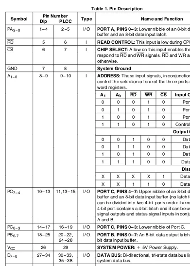
Table 1. Pin Description
Symbol Pin Number Type Name and Function
Dip PLCC
PA3–0 1 – 4 2 – 5 I/O PORT A, PINS 0 – 3:Lower nibble of an 8-bit data output latch/
buffer and an 8-bit data input latch.
RD 5 6 I READ CONTROL:This input is low during CPU read operations.
CS 6 7 I CHIP SELECT:A low on this input enables the 82C55A to
respond to RD and WR signals. RD and WR are ignored otherwise.
GND 7 8 System Ground
A1–0 8 – 9 9 – 10 I ADDRESS:These input signals, in conjunction RD and WR, control the selection of one of the three ports or the control word registers.
A1 A0 RD WR CS Input Operation (Read)
0 0 0 1 0 Port A - Data Bus
0 1 0 1 0 Port B - Data Bus
1 0 0 1 0 Port C - Data Bus
1 1 0 1 0 Control Word - Data Bus
Output Operation (Write)
0 0 1 0 0 Data Bus - Port A
0 1 1 0 0 Data Bus - Port B
1 0 1 0 0 Data Bus - Port C
1 1 1 0 0 Data Bus - Control
Disable Function
X X X X 1 Data Bus - 3 - State
X X 1 1 0 Data Bus - 3 - State
PC7–4 10 – 13 11,13 – 15 I/O PORT C, PINS 4 – 7:Upper nibble of an 8-bit data output latch/ buffer and an 8-bit data input buffer (no latch for input). This port can be divided into two 4-bit ports under the mode control. Each 4-bit port contains a 4-bit latch and it can be used for the control signal outputs and status signal inputs in conjunction with ports A and B.
PC0–3 14 – 17 16 – 19 I/O PORT C, PINS 0 – 3:Lower nibble of Port C.
PB0-7 18 – 25 20 – 22, I/O PORT B, PINS 0 – 7:An bit data output latch/buffer and an 8-24 – 28 bit data input buffer.
VCC 26 29 SYSTEM POWER:a5V Power Supply.
D7–0 27 – 34 30 – 33, I/O DATA BUS:Bi-directional, tri-state data bus lines, connected to 35 – 38 system data bus.
RESET 35 39 I RESET:A high on this input clears the control register and all ports are set to the input mode.
WR 36 40 I WRITE CONTROL:This input is low during CPU write
operations.
PA7–4 37 – 40 41 – 44 I/O PORT A, PINS 4 – 7:Upper nibble of an 8-bit data output latch/ buffer and an 8-bit data input latch.
NC 1, 12, No Connect
23, 34
82C55A
82C55A FUNCTIONAL DESCRIPTION
General
The 82C55A is a programmable peripheral interface device designed for use in Intel microcomputer sys-tems. Its function is that of a general purpose I/O component to interface peripheral equipment to the microcomputer system bus. The functional configu-ration of the 82C55A is programmed by the system software so that normally no external logic is neces-sary to interface peripheral devices or structures.
Data Bus Buffer
This 3-state bidirectional 8-bit buffer is used to inter-face the 82C55A to the system data bus. Data is transmitted or received by the buffer upon execution of input or output instructions by the CPU. Control words and status information are also transferred through the data bus buffer.
Read/Write and Control Logic
The function of this block is to manage all of the internal and external transfers of both Data and Control or Status words. It accepts inputs from the CPU Address and Control busses and in turn, issues commands to both of the Control Groups.
Group A and Group B Controls
The functional configuration of each port is pro-grammed by the systems software. In essence, the CPU ‘‘outputs’’ a control word to the 82C55A. The control word contains information such as ‘‘mode’’, ‘‘bit set’’, ‘‘bit reset’’, etc., that initializes the func-tional configuration of the 82C55A.
Each of the Control blocks (Group A and Group B) accepts ‘‘commands’’ from the Read/Write Control Logic, receives ‘‘control words’’ from the internal data bus and issues the proper commands to its as-sociated ports.
Control Group A - Port A and Port C upper (C7 – C4) Control Group B - Port B and Port C lower (C3 – C0)
The control word register can be both written and read as shown in the address decode table in the pin descriptions. Figure 6 shows the control word format for both Read and Write operations. When the control word is read, bit D7 will always be a logic ‘‘1’’, as this implies control word mode information.
Ports A, B, and C
The 82C55A contains three 8-bit ports (A, B, and C). All can be configured in a wide variety of functional characteristics by the system software but each has its own special features or ‘‘personality’’ to further enhance the power and flexibility of the 82C55A.
Port A.One 8-bit data output latch/buffer and one 8-bit input latch buffer. Both up’’ and ‘‘pull-down’’ bus hold devices are present on Port A.
Port B. One 8-bit data input/output latch/buffer. Only ‘‘pull-up’’ bus hold devices are present on Port B.
Port C.One 8-bit data output latch/buffer and one 8-bit data input buffer (no latch for input). This port can be divided into two 4-bit ports under the mode control. Each 4-bit port contains a 4-bit latch and it can be used for the control signal outputs and status signal inputs in conjunction with ports A and B. Only ‘‘pull-up’’ bus hold devices are present on Port C.
See Figure 4 for the bus-hold circuit configuration for Port A, B, and C.
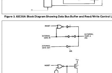
82C55A
231256 – 3
Figure 3. 82C55A Block Diagram Showing Data Bus Buffer and Read/Write Control Logic Functions
*NOTE: 231256 – 4
Port pins loaded with more than 20 pF capacitance may not have their logic level guaranteed following a hardware reset.
Figure 4. Port A, B, C, Bus-hold Configuration
82C55A
82C55A OPERATIONAL DESCRIPTION
Mode Selection
There are three basic modes of operation that can be selected by the system software:
Mode 0 Ð Basic input/output Mode 1 Ð Strobed Input/output Mode 2 Ð Bi-directional Bus
When the reset input goes ‘‘high’’ all ports will be set to the input mode with all 24 port lines held at a logic ‘‘one’’ level by the internal bus hold devices (see Figure 4 Note). After the reset is removed the 82C55A can remain in the input mode with no addi-tional initialization required. This eliminates the need for pullup or pulldown devices in ‘‘all CMOS’’ de-signs. During the execution of the system program, any of the other modes may be selected by using a single output instruction. This allows a single 82C55A to service a variety of peripheral devices with a simple software maintenance routine.
The modes for Port A and Port B can be separately defined, while Port C is divided into two portions as required by the Port A and Port B definitions. All of the output registers, including the status flip-flops, will be reset whenever the mode is changed. Modes may be combined so that their functional definition can be ‘‘tailored’’ to almost any I/O structure. For instance; Group B can be programmed in Mode 0 to monitor simple switch closings or display computa-tional results, Group A could be programmed in Mode 1 to monitor a keyboard or tape reader on an interrupt-driven basis.
231256 – 5 Figure 5. Basic Mode Definitions and Bus
Interface
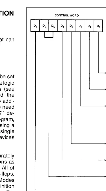
231256 – 6 Figure 6. Mode Definition Format
The mode definitions and possible mode combina-tions may seem confusing at first but after a cursory review of the complete device operation a simple, logical I/O approach will surface. The design of the 82C55A has taken into account things such as effi-cient PC board layout, control signal definition vs PC layout and complete functional flexibility to support almost any peripheral device with no external logic. Such design represents the maximum use of the available pins.
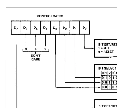
Single Bit Set/Reset Feature
Any of the eight bits of Port C can be Set or Reset using a single OUTput instruction. This feature re-duces software requirements in Control-based appli-cations.
When Port C is being used as status/control for Port A or B, these bits can be set or reset by using the Bit Set/Reset operation just as if they were data output ports.
82C55A
231256 – 7
Figure 7. Bit Set/Reset Format
Interrupt Control Functions
When the 82C55A is programmed to operate in mode 1 or mode 2, control signals are provided that can be used as interrupt request inputs to the CPU. The interrupt request signals, generated from port C, can be inhibited or enabled by setting or resetting the associated INTE flip-flop, using the bit set/reset function of port C.
This function allows the Programmer to disallow or allow a specific I/O device to interrupt the CPU with-out affecting any other device in the interrupt struc-ture.
INTE flip-flop definition:
(BIT-SET)ÐINTE is SETÐInterrupt enable (BIT-RESET)ÐINTE is RESETÐInterrupt disable
Note:
All Mask flip-flops are automatically reset during mode selection and device Reset.
82C55A
Operating Modes
Mode 0 (Basic Input/Output).This functional con-figuration provides simple input and output opera-tions for each of the three ports. No ‘‘handshaking’’ is required, data is simply written to or read from a specified port.
Mode 0 Basic Functional Definitions: # Two 8-bit ports and two 4-bit ports. # Any port can be input or output. # Outputs are latched.
# Inputs are not latched.
# 16 different Input/Output configurations are pos-sible in this Mode.
MODE 0 (BASIC INPUT)
231256 – 8
MODE 0 (BASIC OUTPUT)
231256 – 9
82C55A
MODE 0 Port Definition
A B GROUP A GROUP B
D4 D3 D1 D0 PORT A PORT C Ý PORT B PORT C
(UPPER) (LOWER)
0 0 0 0 OUTPUT OUTPUT 0 OUTPUT OUTPUT
0 0 0 1 OUTPUT OUTPUT 1 OUTPUT INPUT
0 0 1 0 OUTPUT OUTPUT 2 INPUT OUTPUT
0 0 1 1 OUTPUT OUTPUT 3 INPUT INPUT
0 1 0 0 OUTPUT INPUT 4 OUTPUT OUTPUT
0 1 0 1 OUTPUT INPUT 5 OUTPUT INPUT
0 1 1 0 OUTPUT INPUT 6 INPUT OUTPUT
0 1 1 1 OUTPUT INPUT 7 INPUT INPUT
1 0 0 0 INPUT OUTPUT 8 OUTPUT OUTPUT
1 0 0 1 INPUT OUTPUT 9 OUTPUT INPUT
1 0 1 0 INPUT OUTPUT 10 INPUT OUTPUT
1 0 1 1 INPUT OUTPUT 11 INPUT INPUT
1 1 0 0 INPUT INPUT 12 OUTPUT OUTPUT
1 1 0 1 INPUT INPUT 13 OUTPUT INPUT
1 1 1 0 INPUT INPUT 14 INPUT OUTPUT
1 1 1 1 INPUT INPUT 15 INPUT INPUT
MODE 0 Configurations
231256 – 10
82C55A
MODE 0 Configurations(Continued)
231256 – 11
82C55A
MODE 0 Configurations(Continued)
231256 – 12
Operating Modes
MODE 1 (Strobed Input/Output). This functional configuration provides a means for transferring I/O data to or from a specified port in conjunction with strobes or ‘‘handshaking’’ signals. In mode 1, Port A and Port B use the lines on Port C to generate or accept these ‘‘handshaking’’ signals.
Mode 1 Basic functional Definitions:
# Two Groups (Group A and Group B).
# Each group contains one 8-bit data port and one 4-bit control/data port.
# The 8-bit data port can be either input or output Both inputs and outputs are latched.
# The 4-bit port is used for control and status of the 8-bit data port.
82C55A
Input Control Signal Definition
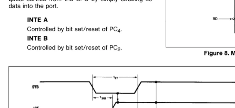
STB (Strobe Input). A ‘‘low’’ on this input loads data into the input latch.
IBF (Input Buffer Full F/F)
A ‘‘high’’ on this output indicates that the data has been loaded into the input latch; in essence, an ac-knowledgement. IBF is set by STB input being low and is reset by the rising edge of the RD input.
INTR (Interrupt Request)
A ‘‘high’’ on this output can be used to interrupt the CPU when an input device is requesting service. INTR is set by the STB is a ‘‘one’’, IBF is a ‘‘one’’ and INTE is a ‘‘one’’. It is reset by the falling edge of RD. This procedure allows an input device to re-quest service from the CPU by simply strobing its data into the port.
INTE A
Controlled by bit set/reset of PC4. INTE B
Controlled by bit set/reset of PC2.
231256 – 13
Figure 8. MODE 1 Input
231256 – 14
Figure 9. MODE 1 (Strobed Input)
82C55A
Output Control Signal Definition
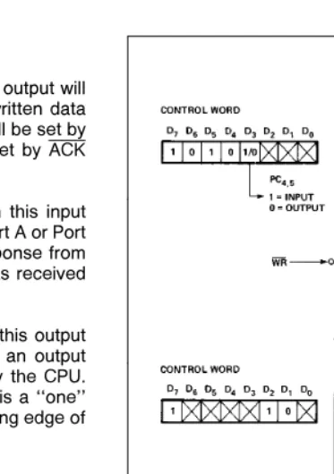
OBF (Output Buffer Full F/F).The OBF output will go ‘‘low’’ to indicate that the CPU has written data out to the specified port. The OBF F/F will be set by the rising edge of the WR input and reset by ACK Input being low.
ACK (Acknowledge Input).A ‘‘low’’ on this input informs the 82C55A that the data from Port A or Port B has been accepted. In essence, a response from the peripheral device indicating that it has received the data output by the CPU.
INTR (Interrupt Request).A ‘‘high’’ on this output can be used to interrupt the CPU when an output device has accepted data transmitted by the CPU. INTR is set when ACK is a ‘‘one’’, OBF is a ‘‘one’’ and INTE is a ‘‘one’’. It is reset by the falling edge of WR.
INTE A
Controlled by bit set/reset of PC6.
INTE B
Controlled by bit set/reset of PC2.
231256 – 15
Figure 10. MODE 1 Output
231256 – 16
Figure 11. MODE 1 (Strobed Output)
82C55A
Combinations of MODE 1
Port A and Port B can be individually defined as input or output in Mode 1 to support a wide variety of strobed I/O applications.
231256 – 17
Figure 12. Combinations of MODE 1
Operating Modes
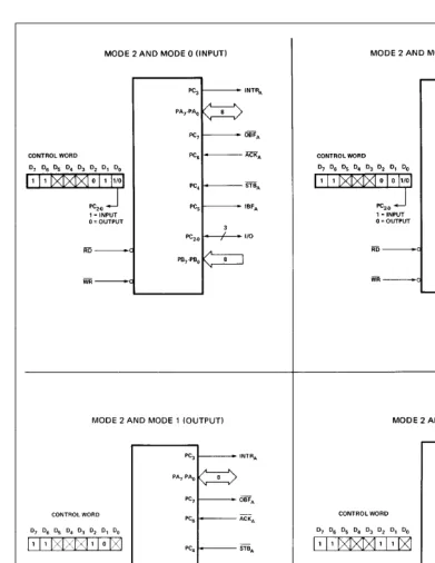
MODE 2 (Strobed Bidirectional Bus I/O).This functional configuration provides a means for com-municating with a peripheral device or structure on a single 8-bit bus for both transmitting and receiving data (bidirectional bus I/O). ‘‘Handshaking’’ signals are provided to maintain proper bus flow discipline in a similar manner to MODE 1. Interrupt generation and enable/disable functions are also available.
MODE 2 Basic Functional Definitions:
# Used in Group Aonly.
# One 8-bit, bi-directional bus port (Port A) and a 5-bit control port (Port C).
# Both inputs and outputs are latched.
# The 5-bit control port (Port C) is used for control and status for the 8-bit, bi-directional bus port (Port A).
Bidirectional Bus I/O Control Signal Definition INTR (Interrupt Request).A high on this output can be used to interrupt the CPU for input or output oper-ations.
Output Operations
OBF (Output Buffer Full).The OBF output will go ‘‘low’’ to indicate that the CPU has written data out to port A.
ACK (Acknowledge).A ‘‘low’’ on this input enables the tri-state output buffer of Port A to send out the data. Otherwise, the output buffer will be in the high impedance state.
INTE 1 (The INTE Flip-Flop Associated with OBF).Controlled by bit set/reset of PC6.
Input Operations
STB (Strobe Input). A ‘‘low’’ on this input loads data into the input latch.
IBF (Input Buffer Full F/F).A ‘‘high’’ on this output indicates that data has been loaded into the input latch.
INTE 2 (The INTE Flip-Flop Associated with IBF).
Controlled by bit set/reset of PC4.
82C55A
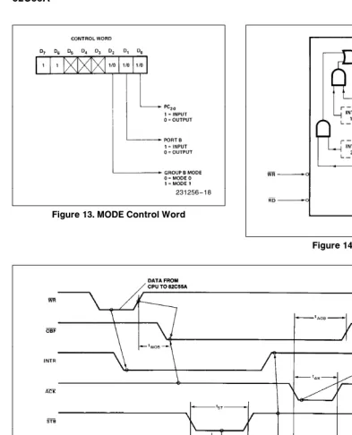
231256 – 18
Figure 13. MODE Control Word
231256 – 19
Figure 14. MODE 2
231256 – 20
Figure 15. MODE 2 (Bidirectional)
NOTE:
Any sequence where WR occurs before ACK, and STB occurs before RD is permissible. (INTReIBF#MASK#STB#RDaOBF#MASK#ACK#WR)
82C55A
231256 – 21
Figure 16. MODE(/4Combinations
82C55A
Mode Definition Summary
MODE 0 MODE 1 MODE 2
IN OUT IN OUT GROUP A ONLY
PA0 IN OUT IN OUT
Ý
PA1 IN OUT IN OUT
Ý
PA2 IN OUT IN OUT
Ý
PA3 IN OUT IN OUT
Ý
PA4 IN OUT IN OUT
Ý
PA5 IN OUT IN OUT
Ý
PA6 IN OUT IN OUT
Ý
PA7 IN OUT IN OUT
Ý
PB0 IN OUT IN OUT Ð
PB1 IN OUT IN OUT Ð
PB2 IN OUT IN OUT Ð
PB3 IN OUT IN OUT Ð MODE 0
PB4 IN OUT IN OUT Ð OR MODE 1
PB5 IN OUT IN OUT Ð ONLY
PB6 IN OUT IN OUT Ð
PB7 IN OUT IN OUT Ð
PC0 IN OUT INTRB INTRB I/O
PC1 IN OUT IBFB OBFB I/O
PC2 IN OUT STBB ACKB I/O
PC3 IN OUT INTRA INTRA INTRA
PC4 IN OUT STBA I/O STBA
PC5 IN OUT IBFA I/O IBFA
PC6 IN OUT I/O ACKA ACKA
PC7 IN OUT I/O OBFA OBFA
Special Mode Combination Considerations
There are several combinations of modes possible. For any combination, some or all of the Port C lines are used for control or status. The remaining bits are either inputs or outputs as defined by a ‘‘Set Mode’’ command.
During a read of Port C, the state of all the Port C lines, except the ACK and STB lines, will be placed on the data bus. In place of the ACK and STB line states, flag status will appear on the data bus in the PC2, PC4, and PC6 bit positions as illustrated by Figure 18.
Through a ‘‘Write Port C’’ command, only the Port C pins programmed as outputs in a Mode 0 group can be written. No other pins can be affected by a ‘‘Write Port C’’ command, nor can the interrupt enable flags be accessed. To write to any Port C output pro-grammed as an output in a Mode 1 group or to
change an interrupt enable flag, the ‘‘Set/Reset Port C Bit’’ command must be used.
With a ‘‘Set/Reset Port C Bit’’ command, any Port C line programmed as an output (including INTR, IBF and OBF) can be written, or an interrupt enable flag can be either set or reset. Port C lines programmed as inputs, including ACK and STB lines, associated with Port C are not affected by a ‘‘Set/Reset Port C Bit’’ command. Writing to the corresponding Port C bit positions of the ACK and STB lines with the ‘‘Set/Reset Port C Bit’’ command will affect the Group A and Group B interrupt enable flags, as illus-trated in Figure 18.
Current Drive Capability
Any output on Port A, B or C can sink or source 2.5 mA. This feature allows the 82C55A to directly drive Darlington type drivers and high-voltage displays that require such sink or source current.
82C55A
Reading Port C Status
In Mode 0, Port C transfers data to or from the pe-ripheral device. When the 82C55A is programmed to function in Modes 1 or 2, Port C generates or ac-cepts ‘‘hand-shaking’’ signals with the peripheral de-vice. Reading the contents of Port C allows the pro-grammer to test or verify the ‘‘status’’ of each pe-ripheral device and change the program flow ac-cordingly.
There is no special instruction to read the status in-formation from Port C. A normal read operation of Port C is executed to perform this function.
INPUT CONFIGURATION
D7 D6 D5 D4 D3 D2 D1 D0
I/O I/O IBFA INTEA INTRA INTEB IBFB INTRB
GROUP A GROUP B OUTPUT CONFIGURATIONS D7 D6 D5 D4 D3 D2 D1 D0
OBFA INTEA I/O I/O INTRA INTEB OBFB INTRB GROUP A GROUP B Figure 17a. MODE 1 Status Word Format
D7 D6 D5 D4 D3 D2 D1 D0
OBFAINTE1IBFAINTE2 INTRA
GROUP A GROUP B
(Defined By Mode 0 or Mode 1 Selection)
Figure 17b. MODE 2 Status Word Format
Interrupt Enable Flag Position Alternate Port C Pin Signal (Mode)
INTE B PC2 ACKB(Output Mode 1) or STBB(Input Mode 1)
INTE A2 PC4 STBA(Input Mode 1 or Mode 2)
INTE A1 PC6 ACKA(Output Mode 1 or Mode 2
Figure 18. Interrupt Enable Flags in Modes 1 and 2
82C55A
ABSOLUTE MAXIMUM RATINGS
*
Ambient Temperature Under BiasÀÀÀÀ0§C toa70§C Storage Temperature ÀÀÀÀÀÀÀÀÀb65§C toa150§C Supply Voltage ÀÀÀÀÀÀÀÀÀÀÀÀÀÀÀÀÀÀb0.5 toa8.0V Operating Voltage ÀÀÀÀÀÀÀÀÀÀÀÀÀÀÀÀÀa4V toa7V Voltage on any InputÀÀÀÀÀÀÀÀÀÀGNDb2V toa6.5V Voltage on any Output ÀÀGNDb0.5V to VCCa0.5V Power Dissipation ÀÀÀÀÀÀÀÀÀÀÀÀÀÀÀÀÀÀÀÀÀÀÀÀ1 Watt
NOTICE: This is a production data sheet. The specifi-cations are subject to change without notice.
*WARNING: Stressing the device beyond the ‘‘Absolute Maximum Ratings’’ may cause permanent damage. These are stress ratings only. Operation beyond the ‘‘Operating Conditions’’ is not recommended and ex-tended exposure beyond the ‘‘Operating Conditions’’ may affect device reliability.
D.C. CHARACTERISTICS
TAe0§C to 70§C, VCCe a5Vg10%, GNDe0V (TAe b40§C toa85§C for Extended Temperture)
Symbol Parameter Min Max Units Test Conditions
VIL Input Low Voltage b0.5 0.8 V
VIH Input High Voltage 2.0 VCC V
VOL Output Low Voltage 0.4 V IOLe2.5 mA
VOH Output High Voltage 3.0 V IOHe b2.5 mA
VCCb0.4 V IOHe b100mA
IIL Input Leakage Current g1 mA VINeVCCto 0V (Note 1)
IOFL Output Float Leakage Current g10 mA VINeVCCto 0V (Note 2)
IDAR Darlington Drive Current g2.5 (Note 4) mA Ports A, B, C Rexte500X Vexte1.7V
IPHL Port Hold Low Leakage Current a50 a300 mA VOUTe1.0V Port A only
IPHH Port Hold High Leakage Current b50 b300 mA VOUTe3.0V Ports A, B, C
IPHLO Port Hold Low Overdrive Current b350 mA VOUTe0.8V
IPHHO Port Hold High Overdrive Current a350 mA V
OUTe3.0V
ICC VCCSupply Current 10 mA (Note 3)
ICCSB VCCSupply Current-Standby 10 mA VCCe5.5V VINeVCCor GND Port Conditions If I/PeOpen/High
O/PeOpen Only With Data Buse
High/Low CSeHigh ReseteLow Pure Inputse
Low/High
NOTES:
1. Pins A1, A0, CS, WR, RD, Reset.
2. Data Bus; Ports B, C. 3. Outputs open.
4. Limit output current to 4.0 mA.
82C55A
CAPACITANCE
TAe25§C, VCCeGNDe0V
Symbol Parameter Min Max Units Test Conditions
CIN Input Capacitance 10 pF Unmeasured plns returned to GND CI/O I/O Capacitance 20 pF
fce1 MHz(5)
NOTE:
5. Sampled not 100% tested.
A.C. CHARACTERISTICS
TAe0§to 70§C, VCCe a5Vg10%, GNDe0V TAe b40§C toa85§C for Extended Temperature
BUS PARAMETERS
READ CYCLE
Symbol Parameter 82C55A-2 Units Test
Min Max Conditions
tAR Address Stable Before RD
v
0 ns tRA Address Hold Time After RDu
0 nstRR RD Pulse Width 150 ns
tRD Data Delay from RD
v
120 ns tDF RDu
to Data Floating 10 75 ns tRV Recovery Time between RD/WR 200 nsWRITE CYCLE
Symbol Parameter 82C55A-2 Units Test
Min Max Conditions
tAW Address Stable Before WR
v
0 nstWA Address Hold Time After WR
u
20 ns Ports A & B20 ns Port C
tWW WR Pulse Width 100 ns
tDW Data Setup Time Before WR
u
100 nstWD Data Hold Time After WR
u
30 ns Ports A & B30 ns Port C
82C55A
OTHER TIMINGS
Symbol Parameter 82C55A-2 Units Test
Min Max Conditions
tWB WRe1 to Output 350 ns
tlR Peripheral Data Before RD 0 ns
tHR Peripheral Data After RD 0 ns
tAK ACK Pulse Width 200 ns
tST STB Pulse Width 100 ns
tPS Per. Data Before STB High 20 ns
tPH Per. Data After STB High 50 ns
tAD ACKe0 to Output 175 ns
tKD ACKe1 to Output Float 20 250 ns
tWOB WRe1 to OBFe0 150 ns
tAOB ACKe0 to OBFe1 150 ns
tSIB STBe0 to IBFe1 150 ns
tRIB RDe1 to IBFe0 150 ns
tRIT RDe0 to INTRe0 200 ns
tSIT STBe1 to INTRe1 150 ns
tAIT ACKe1 to INTRe1 150 ns
tWIT WRe0 to INTRe0 200 ns see note 1
tRES Reset Pulse Width 500 ns see note 2
NOTE:
1. INTR
u
may occur as early as WRv
.2. Pulse width of initial Reset pulse after power on must be at least 50mSec. Subsequent Reset pulses may be 500 ns
minimum. The output Ports A, B, or C may glitch low during the reset pulse but all port pins will be held at a logic ‘‘one’’ level after the reset pulse.
82C55A
WAVEFORMS
MODE 0 (BASIC INPUT)
231256 – 22
MODE 0 (BASIC OUTPUT)
231256 – 23
82C55A
WAVEFORMS
(Continued)MODE 1 (STROBED INPUT)
231256 – 24
MODE 1 (STROBED OUTPUT)
231256 – 25
82C55A
WAVEFORMS
(Continued)MODE 2 (BIDIRECTIONAL)
231256 – 26
Note:
Any sequence where WR occurs before ACK AND STB occurs before RD is permissible. (INTReIBF#MASK#STB#RDaOBF#MASK#ACK#WR)
WRITE TIMING
231256 – 27
READ TIMING
231256 – 28
A.C. TESTING INPUT, OUTPUT WAVEFORM
231256 – 29
A.C. Testing Inputs Are Driven At 2.4V For A Logic 1 And 0.45V For A Logic 0 Timing Measurements Are Made At 2.0V For A Logic 1 And 0.8 For A Logic 0.
A.C. TESTING LOAD CIRCUIT
231256 – 30
*VEXTIs Set At Various Voltages During Testing To Guarantee The Specification. CLIncludes Jig Capacitance.
LAMPIRAN F
ADC0808/ADC0809
8-Bit µP Compatible A/D Converters with 8-Channel
Multiplexer
General Description
The ADC0808, ADC0809 data acquisition component is a monolithic CMOS device with an 8-bit analog-to-digital con-verter, 8-channel multiplexer and microprocessor compatible control logic. The 8-bit A/D converter uses successive ap-proximation as the conversion technique. The converter fea-tures a high impedance chopper stabilized comparator, a 256R voltage divider with analog switch tree and a succes-sive approximation register. The 8-channel multiplexer can directly access any of 8-single-ended analog signals. The device eliminates the need for external zero and full-scale adjustments. Easy interfacing to microprocessors is provided by the latched and decoded multiplexer address inputs and latched TTL TRI-STATE outputs.
The design of the ADC0808, ADC0809 has been optimized by incorporating the most desirable aspects of several A/D conversion techniques. The ADC0808, ADC0809 offers high speed, high accuracy, minimal temperature dependence, excellent long-term accuracy and repeatability, and con-sumes minimal power. These features make this device ideally suited to applications from process and machine control to consumer and automotive applications. For 16-channel multiplexer with common output (sample/hold port) see ADC0816 data sheet. (See AN-247 for more infor-mation.)
Features
n Easy interface to all microprocessors
n Operates ratiometrically or with 5 VDCor analog span
adjusted voltage reference
n No zero or full-scale adjust required
n 8-channel multiplexer with address logic
n 0V to 5V input range with single 5V power supply
n Outputs meet TTL voltage level specifications
n ADC0808 equivalent to MM74C949
n ADC0809 equivalent to MM74C949-1
Key Specifications
n Resolution 8 Bits
n Total Unadjusted Error ±1⁄2LSB and±1 LSB
n Single Supply 5 VDC
n Low Power 15 mW
n Conversion Time 100 µs
Connection Diagrams
Dual-In-Line Package
00567211 Order Number ADC0808CCN or ADC0809CCN
See NS Package J28A or N28A
Molded Chip Carrier Package
00567212 Order Number ADC0808CCV or ADC0809CCV
See NS Package V28A
Ordering Information
TEMPERATURE RANGE −40˚C to +85˚C
Error ±1⁄2LSB Unadjusted ADC0808CCN ADC0808CCV
±1 LSB Unadjusted ADC0809CCN ADC0809CCV
Package Outline N28A Molded DIP V28A Molded Chip Carrier
Absolute Maximum Ratings
(Notes 2, 1)If Military/Aerospace specified devices are required, please contact the National Semiconductor Sales Office/ Distributors for availability and specifications.
Supply Voltage (VCC) (Note 3) 6.5V
Voltage at Any Pin −0.3V to
(VCC+0.3V) Except Control Inputs
Voltage at Control Inputs −0.3V to +15V (START, OE, CLOCK, ALE, ADD A, ADD B, ADD C) Storage Temperature Range −65˚C to +150˚C Package Dissipation at TA=25˚C 875 mW Lead Temp. (Soldering, 10 seconds)
Dual-In-Line Package (plastic) 260˚C
Molded Chip Carrier Package
Vapor Phase (60 seconds) 215˚C
Infrared (15 seconds) 220˚C
ESD Susceptibility (Note 8) 400V
Operating Conditions
(Notes 1, 2) Temperature Range (Note 1) TMIN≤TA≤TMAXADC0808CCN,ADC0809CCN −40˚C≤TA≤+85˚C ADC0808CCV, ADC0809CCV −40˚C≤TA≤+85˚C Range of VCC(Note 1) 4.5 VDCto 6.0 VDC
Electrical Characteristics
Converter Specifications:VCC=5 VDC=VREF+, VREF(−)=GND, TMIN≤TA≤TMAXand fCLK=640 kHz unless otherwise stated.
Symbol Parameter Conditions Min Typ Max Units ADC0808
Total Unadjusted Error 25˚C ±1⁄2 LSB
(Note 5) TMINto TMAX ±3⁄4 LSB
ADC0809
Total Unadjusted Error 0˚C to 70˚C ±1 LSB
(Note 5) TMINto TMAX ±11⁄4 LSB
Input Resistance From Ref(+) to Ref(−) 1.0 2.5 kΩ
Analog Input Voltage Range (Note 4) V(+) or V(−) GND−0.10 VCC+0.10 VDC
VREF(+) Voltage, Top of Ladder Measured at Ref(+) VCC VCC+0.1 V
Voltage, Center of Ladder VCC/2-0.1 VCC/2 VCC/2+0.1 V
VREF(−) Voltage, Bottom of Ladder Measured at Ref(−) −0.1 0 V
IIN Comparator Input Current fc=640 kHz, (Note 6) −2 ±0.5 2 µA
Electrical Characteristics
Digital Levels and DC Specifications:ADC0808CCN, ADC0808CCV, ADC0809CCN and ADC0809CCV, 4.75≤VCC≤5.25V,
−40˚C≤TA≤+85˚C unless otherwise noted
Symbol Parameter Conditions Min Typ Max Units
ANALOG MULTIPLEXER
IOFF(+) OFF Channel Leakage Current VCC=5V, VIN=5V,
TA=25˚C 10 200 nA
TMINto TMAX 1.0 µA
IOFF(−) OFF Channel Leakage Current VCC=5V, VIN=0,
TA=25˚C −200 −10 nA
TMINto TMAX −1.0 µA
CONTROL INPUTS
VIN(1) Logical “1” Input Voltage VCC−1.5 V
VIN(0) Logical “0” Input Voltage 1.5 V
IIN(1) Logical “1” Input Current VIN=15V 1.0 µA
(The Control Inputs)
IIN(0) Logical “0” Input Current VIN=0 −1.0 µA
(The Control Inputs)
Electrical Characteristics
(Continued)Digital Levels and DC Specifications:ADC0808CCN, ADC0808CCV, ADC0809CCN and ADC0809CCV, 4.75≤VCC≤5.25V, −40˚C≤TA≤+85˚C unless otherwise noted
Symbol Parameter Conditions Min Typ Max Units
DATA OUTPUTS AND EOC (INTERRUPT)
VOUT(1) Logical “1” Output Voltage VCC= 4.75V IOUT= −360µA IOUT= −10µA
2.4 4.5
V(min) V(min) VOUT(0) Logical “0” Output Voltage IO=1.6 mA 0.45 V VOUT(0) Logical “0” Output Voltage EOC IO=1.2 mA 0.45 V
IOUT TRI-STATE Output Current VO=5V 3 µA
VO=0 −3 µA
Electrical Characteristics
Timing SpecificationsVCC=VREF(+)=5V, VREF(−)=GND, tr=tf=20 ns and TA=25˚C unless otherwise noted.
Symbol Parameter Conditions MIn Typ Max Units
tWS Minimum Start Pulse Width (Figure 5) 100 200 ns
tWALE Minimum ALE Pulse Width (Figure 5) 100 200 ns
ts Minimum Address Set-Up Time (Figure 5) 25 50 ns
tH Minimum Address Hold Time (Figure 5) 25 50 ns
tD Analog MUX Delay Time RS=0Ω(Figure 5) 1 2.5 µs
From ALE
tH1, tH0 OE Control to Q Logic State CL=50 pF, RL=10k (Figure 8) 125 250 ns t1H, t0H OE Control to Hi-Z CL=10 pF, RL=10k (Figure 8) 125 250 ns tc Conversion Time fc=640 kHz, (Figure 5) (Note 7) 90 100 116 µs
fc Clock Frequency 10 640 1280 kHz
tEOC EOC Delay Time (Figure 5) 0 8+2 µS Clock
Periods
CIN Input Capacitance At Control Inputs 10 15 pF
COUT TRI-STATE Output At TRI-STATE Outputs 10 15 pF
Capacitance
Note 1: Absolute Maximum Ratings indicate limits beyond which damage to the device may occur. DC and AC electrical specifications do not apply when operating the device beyond its specified operating conditions.
Note 2: All voltages are measured with respect to GND, unless othewise specified.
Note 3: A zener diode exists, internally, from VCCto GND and has a typical breakdown voltage of 7 VDC.
Note 4: Two on-chip diodes are tied to each analog input which will forward conduct for analog input voltages one diode drop below ground or one diode drop greater than the VCCn supply. The spec allows 100 mV forward bias of either diode. This means that as long as the analog VINdoes not exceed the supply voltage
by more than 100 mV, the output code will be correct. To achieve an absolute 0VDCto 5VDCinput voltage range will therefore require a minimum supply voltage of
4.900 VDCover temperature variations, initial tolerance and loading.
Note 5: Total unadjusted error includes offset, full-scale, linearity, and multiplexer errors. SeeFigure 3. None of these A/Ds requires a zero or full-scale adjust. However, if an all zero code is desired for an analog input other than 0.0V, or if a narrow full-scale span exists (for example: 0.5V to 4.5V full-scale) the reference voltages can be adjusted to achieve this. SeeFigure 13.
Note 6: Comparator input current is a bias current into or out of the chopper stabilized comparator. The bias current varies directly with clock frequency and has little temperature dependence (Figure 6). See paragraph 4.0.
Note 7: The outputs of the data register are updated one clock cycle before the rising edge of EOC.
Note 8: Human body model, 100 pF discharged through a 1.5 kΩresistor.
Functional Description
Multiplexer.The device contains an 8-channel single-ended analog signal multiplexer. A particular input channel is se-lected by using the address decoder.Table 1shows the input states for the address lines to select any channel. The address is latched into the decoder on the low-to-high tran-sition of the address latch enable signal.
TABLE 1.
SELECTED ADDRESS LINE ANALOG CHANNEL C B A
IN0 L L L
IN1 L L H
IN2 L H L
IN3 L H H
IN4 H L L
IN5 H L H
IN6 H H L
IN7 H H H
CONVERTER CHARACTERISTICS
The Converter
The heart of this single chip data acquisition system is its 8-bit analog-to-digital converter. The converter is designed to give fast, accurate, and repeatable conversions over a wide range of temperatures. The converter is partitioned into 3 major sections: the 256R ladder network, the successive approximation register, and the comparator. The conver