_________________________________________ * Corresponding author
IMPROVED REAL-TIME SCAN MATCHING USING CORNER FEATURES
H. A. Mohamed a,*, A. M. Moussa a,b, M. M. Elhabiby c, N. El-Sheimy a, Abu B. Sesay d a
Department of Geomatics Engineering, University of Calgary, Calgary, Alberta, Canada - (haytham.abdalla, amelsaye, elsheimy)@ucalgary.ca
b
Department of Electrical Engineering and Computer Engineering, Port-Said University, Egypt c
Public Works Department, Ain Shams University, Cairo, Egypt - [email protected] d
Department of Electrical and Computer Engineering, University of Calgary, Calgary, Alberta, Canada - [email protected]
Commission V, WG V/3
KEY WORDS: Scan Matching, SLAM, Laser Range Finder, Point Registration, Least Squares, ICP, Line Tracking, PCA ABSTRACT:
The automation of unmanned vehicle operation has gained a lot of research attention, in the last few years, because of its numerous applications. The vehicle localization is more challenging in indoor environments where absolute positioning measurements (e.g. GPS) are typically unavailable. Laser range finders are among the most widely used sensors that help the unmanned vehicles to localize themselves in indoor environments. Typically, automatic real-time matching of the successive scans is performed either explicitly or implicitly by any localization approach that utilizes laser range finders. Many accustomed approaches such as Iterative Closest Point (ICP), Iterative Matching Range Point (IMRP), Iterative Dual Correspondence (IDC), and Polar Scan Matching (PSM) handles the scan matching problem in an iterative fashion which significantly affects the time consumption. Furthermore, the solution convergence is not guaranteed especially in cases of sharp maneuvers or fast movement. This paper proposes an automated real-time scan matching algorithm where the matching process is initialized using the detected corners. This initialization step aims to increase the convergence probability and to limit the number of iterations needed to reach convergence. The corner detection is preceded by line extraction from the laser scans. To evaluate the probability of line availability in indoor environments, various data sets, offered by different research groups, have been tested and the mean numbers of extracted lines per scan for these data sets are ranging from 4.10 to 8.86 lines of more than 7 points. The set of all intersections between extracted lines are detected as corners regardless of the physical intersection of these line segments in the scan. To account for the uncertainties of the detected corners, the covariance of the corners is estimated using the extracted lines variances. The detected corners are used to estimate the transformation parameters between the successive scan using least squares. These estimated transformation parameters are used to calculate an adjusted initialization for scan matching process. The presented method can be employed solely to match the successive scans and also can be used to aid other accustomed iterative methods to achieve more effective and faster converge. The performance and time consumption of the proposed approach is compared with ICP algorithm alone without initialization in different scenarios such as static period, fast straight movement, and sharp manoeuvers.
1. INTRODUCTION
The capability to take decisions without human intervention is called autonomy (Haibin, 2014). Thus, to autonomously navigate a robot or unmanned vehicle in an indoor environment, this requires an accurate estimation of the vehicle’s navigation parameters (i.e. position, velocity and orientation). Vehicle localization can be a challenging task because GPS can fail to provide reliable position because of multipath problem, loss of line of sight and/or signal attenuation (Wang, 2014). Even if the GPS signal is received by any other means, the accuracy of the received measurements will not be appropriate for indoor navigation. Indoor localization approaches assume either known or unknown environment (Kai, 2003). The complexity of the localization problem is increased for completely unknown environment due to the absence of the environment representation.
Simultaneous localization and mapping (SLAM) is one of the basic techniques in addressing this problem (Machado, 2013). SLAM is based on constructing a map of the surrounding environment whilst at the same time estimating the vehicle’s position inside this environment. Mapping the unknown environment is a problem of interpreting the information gathered from the sensor(s) of the moving vehicle into a given representation. Therefore, the main concern is how to interpret the sensor(s) data and how to represent the current environment
as well. Consequently, this can be described by the following question “What does the surrounding environment look like?”. Scan matching is a key step in a lot of SLAM approaches. Typically, the relative parameters of the vehicle are estimated from the matching of the successive scans (Shu, 2013). Furthermore, constructing the map is performed from the scan matching as well. Many accustomed approaches have been proposed to perform the scan matching between the successive scans such as Iterative Closest Point (ICP) (Besl and McKay, 1992), Iterative Matching Range Point (IMRP) (Feng and Milios, 1994), Iterative Dual Correspondence (IDC) (Feng and Milios, 1994), and Polar Scan Matching (PSM) (Diosi and Kleeman, 2005). The first three algorithms are working in Cartesian coordinate system, whereas the PSM is using polar coordinate system. The fundamental difference between these algorithms is the method of finding the correspondences between the successive scan frames. The ICP algorithm assigns correspondences between points based on the shortest Euclidean distance. IMPR selects the correspondence with the same range as the reference point and within a defined region
Iteration is a common aspect in all these algorithms because of nonlinearity of the model. Thus, they are relatively time consuming. Furthermore, the solution convergence is not guaranteed especially at the cases of sharp rotation or fast movement, which motivates the use of other aiding sensor such as odometer, IMU into the matching process.
This paper proposes an automated real-time scan matching algorithm where the matching process is initialized using the detected corners. This initialization step aims to increase the convergence probability and to limit the number of iterations needed for convergence. The corner detection is preceded by line extraction from the laser scans. The presented method can be employed solely to match the successive scans and also can be used to aid other accustomed iterative methods to achieve more effective and faster converge. The proposed algorithm utilizes a sole 2D 36 °laser scan range finder for data collection.
This paper is organized as follows: Section 2 describes the overview of the proposed algorithm structure. The used methodology is explained in two phases, where Section 3 illustrates the first phase for linear matching, while the second phase, which is the corner registration, is demonstrated in Section 4. The experimental results are presented and discussed in Section 5, and finally the conclusion is given in Section 6.
2. OVERVIEW OF THE PROPOSED ALGORITHM
STRUCTURE
Figure 1. Overall structure of the proposed algorithm
Figure 1 shows the overall structure of the proposed algorithm. For every two successive scans, the proposed algorithm starts by extracting the lines from the reference and current point clouds. The extracted lines are matched after accepting mutual compatibility with the previous scan lines. The set of all intersections between extracted lines are detected as corners regardless of the physical intersection of these line segments from the scan. The detected corners are used to estimate the transformation parameters between the successive scan using
least squares. These estimated transformation parameters are used to calculate an adjusted initialization for scan matching process of the current scan point cloud. Finally, an iterative scan matching algorithm such as ICP is conducted between the adjusted current frame and the reference frame.
3. PHASE I: LINE MATCHING 3.1 Line Extraction
The used laser scanner range finder is RPLIDAR 36 °. Usually, the raw measurements of the laser scanner are 2D point cloud data represented as polar coordinates ��, �� in the laser scanner coordinate local frame (l-frame). Hence, the raw measurements of the laser scanner are converted to the Cartesian coordinates �, � .
Figure 2 shows the extracted lines of a point cloud data for one scan using the line tracking algorithm in the laser scanner l-frame. The line numbers represent their order in the scan, whilst the red asterisk shows the laser scanner position.
Figure 2. Point cloud data and its extracted lines using line tracking algorithm for one scan in the l-frame
The line tracking (LT) algorithm is applied to cluster the point cloud into groups (Leonardo, 2013). The line that fits each group is estimated using principle component analysis (PCA). By calculating the eigenvectors and eigenvalues of the covariance matrices of the point’s coordinates of each group in the data set, the eigenvector with the highest eigenvalue represents the principle direction of the group. While the second eigenvector represents the robustness of each line. The extracted lines of a small number of points less than a threshold (seven points) is excluded.
To evaluate the probability of line availability in indoor environments, various data sets, offered by different research groups, have been tested and the mean number of extracted lines per scan for these data sets is ranging from 4.10 to 8.86 lines of more than seven points. Figure 3 shows the tested data sets which include the MIT Killian Court, MIT CSAIL Building, Intel Research Lab Seattle, ACES Building at the University of Texas, and building 079 University of Freiburg respectively (Burgard, 2009).
(a) (b)
(c) (d)
(e)
Figure 3. Maps for different data sets are used. (a) MIT Killian Court (b) MIT CSAIL Building (c) Inteal Research Lab Seattle (d) ACES Building at the University of Texas (e) building 079
University of Freiburg
Figure 4 shows a histogram for the extracted lines count in the entire data set of the building 079 University of Freiburg.
Figure 4. Histogram of number of lines detected in the building 079 University of Freiburg data set
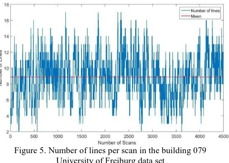
Figure 5 shows the total number of lines per scan, which is represented by the blue line, for the building 079 University of Freiburg data set. Further, the red dotted line presents the mean lines count.
Figure 5. Number of lines per scan in the building 079 University of Freiburg data set
Figure 6 demonstrates the execution time of the lines extraction per scan in the building 079 University of Freiburg data set.
Figure 6. Execution time of the lines extraction in the building 079 University of Freiburg data set
Table 1 lists the line availability and extraction time for different data sets. All the extracted lines are composed of more than seven points.
Data set Name
MIT Killian
MIT CSAIL
Intel Lab
ACES Building
Freiburg Building Number of
Scans 17481 1989 13632 7375 4496
Mean number of
lines
4.24 8.80 4.10 4.21 8.86
Percentage of less than three
lines
11.75 0.10 18.64 15.18 0.13
Mean Execution Time [ms]
3.71 8.93 3.45 4.03 7.41
Table 1. Line availability and extraction time for different data sets
3.2 Line Matching
The extracted lines in the current scan frame should be matched with the reference scan frame lines to enable the matching of the corners. Thence, the angle differences between all lines of the current scan frame are computed with all reference lines using the vector dot product. The matching candidate lines are chosen, from the current scan with respect to the reference scan, according to an angle threshold. Furthermore, the
orthogonal distance to each line is calculated from the laser scanner, which is the origin of the l-frame, and the intersection points between the orthogonal lines with all lines are computed as well. Thus, from the matched candidate lines, the line with the smallest difference of the orthogonal distance and the smallest Euclidean distance of the intersection points is selected to be the matched line in the current scan. Otherwise, there is no matching.
Figure 7. Two successive scans presenting the reference and current scans
Figure 7 demonstrates the matched lines, having same colour, in two successive scans. Each line is represented by an index number. The red asterisk shows the position of the laser scanner in the l-frame, while the black asterisks present the intersection points between the orthogonal lines from the laser scanner and each line in the scan frame.
3.3 Corners Calculation
Thereafter, the set of all intersections between matched lines are detected as corners unrelatedly of the physical intersection of these line segments in the scan. To account for the uncertainties of the detected corners, the covariance of the corners �� is estimated using the extracted lines variances. For each matched line, two boundary (deviation) lines are built around the matched line using the second eigenvalue which represents the precision of the line. The confidence region, for each corner, is computed from the intersections of these boundary lines.
Figure 8 depicts the confidence ellipse region. The green dashed lines present the boundary lines; it is scaled twenty five times. The red ellipses are the confidence regions. Subsequently, the covariance matrices are employed in the least squares registration step.
Figure 8. Confidence ellipse region
4. PHASE II: CORNERS REGISTERATION The detected corners and their covariance matrices, from phase one, are used to estimate the transformation parameters between the successive scan using weighted least squares. These estimated transformation parameters are used to calculate an adjusted initialization for scan matching process. Matching
corners is more consistent correspondence scheme that might lead to a better solution/convergence.
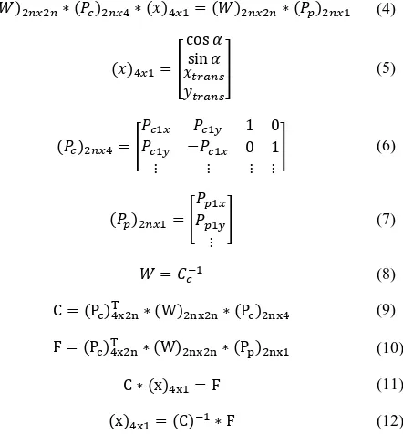
The successive corners relation can be expressed as given:
� ∗ �� �= �� � (1)
cos α ��+ sin α ��+ �� = �� (2)
− sin α ��+ cos α ��+ �� = �� (3)
where T = transformation matrix
P�= corners points from the current scan frame
Equation (1) is adjusted in order to minimize the weighted sum of the squares of the residual, and W is the point’s weight matrix, which is represented as given:
� � �∗ �� � ∗ = � � �∗ �� � (4)
Ultimately, the homogeneous transformation matrix is computed from the weighted least square using corners registration (Aghamohammadi, 2007).
� = [− sin � cos �cos � sin � ���� ] (13)
After approaching the adjusted current scan point cloud to the reference one, iterative algorithm for example ICP is utilized as a fine tuning step for the scan matching process.
Reference Scan Current Scan
5. EXPERIMENTAL RESULTS
The registration performance and time consumption of the proposed approach are compared with using the ICP algorithm alone without initialization in different scenarios such as static period, fast straight movement, and sharp manoeuvers.
The next figures present the three different scenarios. Figure 9 shows the scan matching results between two successive scans during a static period using the ICP and the proposed algorithm. The matching RMSEs between the matched points in the ICP and the proposed algorithm for the three scenarios are presented in Table 2.
The two algorithms have approximately the same registration performance during the static period because the probability of correct selection of the correspondences in the reference frame is approximately the same. Nevertheless, the proposed approach is slightly better than ICP.
Figure 9. Scan matching results during the static scenario from ICP and the proposed algorithm
Figure 10 demonstrates the scan matching error in the previous figure. Furthermore, the one sigma ellipse is representing the matching error in the x and y directions.
Figure 10. One sigma ellipse representing the scan matching error during the static scenario
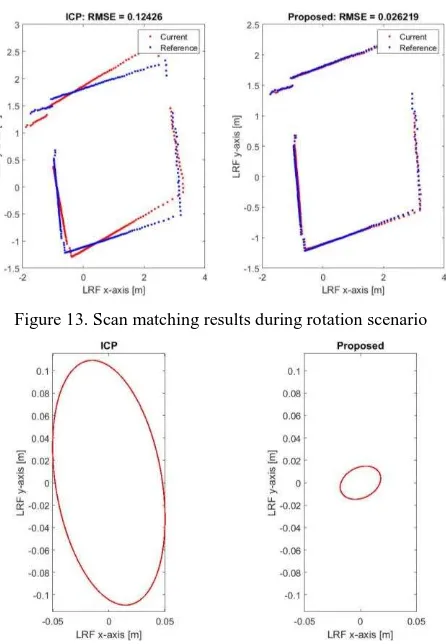
Figure 11 to Figure 14 illustrate the other two scenarios. Obviously, the ICP algorithm fails to converge due to the bad data association process, thus it could not coincide with the two successive scan frames accurately. On the other hand, the proposed algorithm succeeds to assign good correspondences because of matching corners is more reliable than using the entire point cloud. Thus, the two consecutive scan frames are almost corresponded as shown in Figure 11 and Figure 13.
Figure 11. Scan matching results during fast straight movement scenario
Figure 12. Scan matching error during the fast straight movement scenario
Figure 13. Scan matching results during rotation scenario
Figure 14. Scan matching error during the rotation scenario
From Table 2, it is clear that the proposed algorithm aids the ICP to converge especially during the fast movement and sharp rotation.
Matching RMSE [cm]
Algorithm Static Straight Rotation
Proposed 2.6209 1.7879 2.6219
ICP 2.6542 6.5976 12.426
Table 2. Matching RMSE comparison between the proposed algorithm and ICP
Figure 15 depicts the matching RMSEs for every scan in the data set and the mean is 5.85 and 9.64 cm for the proposed algorithm and ICP respectively.
Figure 15. The mapping RMSE for each scan in the data set
Table 3 shows that the proposed algorithm decreases the number of iteration of the ICP algorithm. Moreover, it reduces the time consumption as well.
Mean
Algorithm Number of iterations Time consumption [s]
Proposed 10.0663 0.0264
ICP 14.9669 0.0325
Table 3. Number of iterations and time consumption for the proposed and ICP algorithms
Figure 16 to Figure 18 depict the matching convergence during the three scenarios. It is clear that the proposed algorithm aided the ICP algorithm through several aspects. Firstly, the proposed algorithm starts in a good matching level in the three scenarios. Secondly, the matching convergence level is better during the fast straight movement and sharp rotation. Thirdly, the convergence time is faster in all scenarios even in the static one.
Figure 16. Matching convergence in one scan during the static period
Figure 17. Matching convergence in one scan during the fast straight movement period
Figure 18. Matching convergence in one scan during the rotation period
6. CONCLUSION
In this paper, an automated real-time scan matching algorithm is proposed, where the matching process is initialized using detected corners. This initialization step aims to increase the convergence probability and to limit the number of iterations needed for absolute convergence. The proposed algorithm can be employed solely to match the successive scans and also can be used to aid other accustomed iterative methods to achieve more effective and faster converge. The performance and time consumption of the proposed approach is compared with ICP algorithm in different scenarios such as static period, fast straight movement, and sharp manoeuvers. The RMS value of the neighbour points distance between scans after scan matching of the proposed algorithm in the three scenarios are 2.62, 1.78, and 2.62 cm respectively. On the other hand, the ICP achieves 2.65, 6.59, and 12.42 cm respectively. Furthermore, the number of iterations needed for convergence, comparing with using the ICP algorithm alone, is reduced by 32.7% and the consumption time is reduced by 18.7% as well. The performance of the ICP algorithm is improved when it is used with the proposed algorithm rather than when it is used alone, especially during the harsh conditions such as fast movements and sharp rotations.
These results indicate the significance of the proposed approach for scan matching through improving matching accuracy and optimizing the processing time, which qualify the approach for real time system implementations.
ACKNOWLEDGEMENTS
This work was supported by Dr. Naser El-Sheimy research funds from NSERC and Canada Research Chairs programs. Thanks also goes to the funding of the first author by the Egyptian government.
REFERENCES
A. A. Aghamohammadi, H. D. Taghirad, A. H. Tamjidi, and E. Mihankhah, 2007. Feature-Based Laser Scan Matching For Accurate and High Speed Mobile Robot Localization, In: 3rd European Conference on Mobile Robots (ECMR), Freiburg, Germany.
Haibin Duan, Pei Li, 2014. Bio-inspired Computation in Unmanned Aerial Vehicles. Springer Heidelberg New York Dordrecht London, pp. 6-11.
Machado S., David P., and P. Rocha, 2013. An Evaluation of 2D SLAM Techniques Available in Robot Operating System, In: the IEEE international Symposium on Safty, Security, and Rescue Robotics (SSRR), Linkoping, Sweden.
Besl, P.J. and H.D. McKay, 1992. "A method for registration of 3-D shapes", Pattern Analysis and Machine Intelligence, IEEE Transactions. 14(2): p. 239-256.
Feng Lu and Milios E.E., 1994. Robot pose estimation in unknown environments by matching 2D range scans, In: the IEEE Computer Society Conference on Computer Vision and Pattern Recognition (CVPR), vol., no., pp.935-938.
Fredy Tungadi and Lindsay Kleeman, 2007. Multiple Laser Polar Scan Matching with Application to SLAM, In: Australian Conference on Robotics and Automation (ACRA), Brisbane, Australia.
Diosi, A. and Kleeman, L., 2005. Laser Scan Matching in
polar coordinates with application to SLAM, In: the
IEEE/RSJ International Conference on Intelligent Robots and Systems (IROS), vol., no., pp. 3317-3322.
L. Shu, S, 2013. High Speed and Accurate Laser Scan
Matching using Classified Features, In: the IEEE
International Symposium on Robotics and Sensors Environments (ROSE), Washington DC, USA, pp. 61-66.
F. Wang, K. Wang, S. Lai, S. K. Phang, B. M. Chen, T. H. Lee, June, 2014. An Efficient UAV Navigation Solution for Confined but Partially Known Indoor Environments, In: the 11th IEEE International Conference on Control & Automation (ICCA), Taichung, Taiwan.
Kai Oliver Arras, 2003. Feature-Based Robot Navigation in Known and Unknown Environments. PhD Thesis, the faculty of Science and Technology Engineering, Lausanne federal polytechnic university, Lausanne, Switzerland, pp 1-3.
W. Burgard, C. Stachiniss, G. Grisetti, B. Steder, R. Kummerle, C. Dornhege, M. Ruhnke, A. Kleiner, and Juan D. Tardos, 2009. A Comparison of SLAM Algorithms Based on a Graph of Relations, In: the IEEE/RSJ International Conference on Intelligent Robots and Systems (IROS), St. Louis, MO, USA.
Leonardo R. Munoz, Moises G. Villanueva, and Carlos A. Lara Alvarez, 2013. An Extended Line Tracking Algorithm. In: the IEEE International Autumn Meeting on Power, Electronics and Computing (ROPEC), Mexico City, Mexico.