CLOSE RANGE DIGITAL PHOTOGRAMMETRY APPLIED TO TOPOGRAPHY AND
LANDSLIDE MEASUREMENTS
Wen-Cheng Liu a,b,*, Wei-Che Huanga,c a
Department of Civil and Disaster Prevention Engineering, National United University, Miaoli 36063, Taiwan b Taiwan Typhoon and Flood Research Institute, National Applied Research Laboratories, Taipei 10093, Taiwan
c
Ph.D. Program in Materials and Chemical Engineering, National United University, Miaoli 36063, Taiwan [email protected]
Commission V, WG V/5
KEY WORDS: Close range; photogrammetry, Direct linear transformation, Topography, Landslide, Image matching, Huoyen Shan
ABSTRACT:
Landslide monitoring is a crucial tool for the prevention of hazards. It is often the only solution for the survey and the early-warning of large landslides cannot be stabilized. The objective of present study is to use a low-cost image system to monitor the active landslides. We adopted the direct linear transformation (DLT) method in close range digital photogrammetry to measure terrain of landslide at the Huoyen Shan, Miaoli of central Taiwan and to compare measured results with e-GPS. The results revealed that the relative error in surface area was approximately 1.7% as comparing the photogrammetry with DLT method and e-GPS measurement. It showed that the close range digital photogrammetry with DLT method had the availability and capability to measure the landslides. The same methodology was then applied to measure the terrain before landslide and after landslide in the study area. The digital terrain model (DTM) was established and then was used to calculate the volume of the terrain before landslide and after landslide. The volume difference before and after landslides was 994.16 m3.
1. INTRODUCTION
Photogrammetry is a branch of technology, science, and art where reliable results are obtained by recording, measuring, explicating the emitted electromagnetic energy and topographic images given shape by physical objects and reflected beams from surrounding formed by them (Abdel-Aziz and Karara, 1971). In general, photogrammetry is divided into two categories: aerial and terrestrial photogrammetry. In aerial photogrammetry, images are acquired via overhead shots from an aircraft, providing topographic maps and land use details. In terrestrial photogrammetry, images are obtained at locations near or on the surface of the earth and provided detailed dimensional information of an object. When the object size and the camera-to-object distance are both less than 100 m, terrestrial photogrammetry is defined as close range photogrammetry. An approach where imagines are obtained around an object with highly convergent camera orientations, generally points towards the center of the object (Cooper and Ronson, 2000; Sheng and Gong, 2014). Moreover, close range photogrammetry offers the possibility of obtaining three-dimensional coordinates of an object from two-three-dimensional digital images in a rapid, accurate, reliable, flexible, and economical way. This makes it an ideal tool for precise industrial measurement (Fraser, 1993). Close range photogrammetric systems have been used successful for measurements in fluid physics experiments (Maas et al., 2002), underwater archeological surveying (Green et al., 2002), and monitoring the thermal deformation of steel beams (Fraser and Riedel, 2000), for mapping low relief fluvial geomorphic features ranging from 10 to 100 m2 (Heritage et al., 1998), for surveying of cultural heritage monuments and historical buildings (Mills and Barber, 2004; Arias et al., 2005; Yastikil, 2007; Yilmaz et al., 2007; Yilmaz et al., 2008; Liu et al., 2012;
Reinoso et al., 2014), and for modeling of mouldboard plough surfaces (Aguilar et al., 2005).
Travelletti et al. (2012) reported that three main categories of ground-based platforms allow continuous monitoring (Casagli et al., 2004; Delacourt et al., 2007). Three main categories of ground-based remote sensing techniques are used in landslide monitoring; Ground-Based Synthetic Aperture Radar Interferometry (GB-InSAR), Terrestrial photogrammetry (i.e. close range photogrammetry). The main advantages and disadvantages of these techniques were reviewed and presented. They documented that the implementation, operating, and equipment costs of close range photogrammetry are much lower than GB-InSAR and TLS. The technique includes acquiring digital RGB imagines represented using a matrix of intensity value recorded at each pixel of the camera from a spot very close to the ground (Jiang et al., 2008; Fraser, 2013; Tang and Fritsch, 2013). In the current condition, the application of terrestrial imagines for landslide monitoring is mostly related to the production of digital elevation models for image ortho-rectification, sediment budget analysis (Pesci et al., 2004; Cardenal et al., 2008), and the characterization of slope morpho-structure (Sturzenegger and Stead, 2009).
The short duration of field work measuring time is a remarkable feature of close range digital photogrammetry. Photogrammetric works are normally performed without any contact with the object. The objective of this work is to establish digital terrestrial model (DTM) using close range digital photogrammetry and e-GPS at the Huoyen Shan of central Taiwan and to ascertain the capability and reliability with close range digital photogrammetry. In the landslide area, the close range digital photogrammetry with direct linear transformation (DLT) and correlation coefficient methods for image matching were used to build DTMs before and after landslides. The volume of landslide was then calculated through the DTMs.
2. MATERIALS AND METHODS 2.1 Close Range Digital Photogrammetry
Close range digital photogrammetry measures objects directly from photographs or digital imagines captured with a camera at close range (Atkinson, 1996; Fraser, 1996). The basic model in close range digital photogrammetry is the central perspective projection. The primary coordinate system is positioned arbitrarily in object space, while the secondary system as its origin at the perspective camera center O, its z-axis coincides with the principal axis and is directed away from the imagine plane (Figure 1). The scale factor is set to unity (Atkinson, 1996; Arias et al., 2007).
Figure 1. The central perspective projection
In the primary system, we have the coordinates of the perspective center, O, and an object point in space A: (Xo, Yo, Zo) and (XA, YA, ZA), respectively. The projection of A, through O, in the imagine plane, expressed in the secondary system, gives the coordinates of point a: (
x
a,y
a,f), where f is theprincipal distance called effective focal length, between O and principal point, P’. Point A and a are called homologous. positive scalar quantity proportional to the object distance from A to O.
The reverse transform is given as
The third equation of the reverse transform above can be written explicitly in terms of the scaling and substituted in the other two equations, resulting in the collinearity equations:
)]
coordinates of that point (Mikhail et al., 2001).1 2 3 4 equations can be calculated by means of 6 control points whose coordinates are known in both systems (image coordinate system and object coordinate system).
2.3 Imagine Matching
Image matching is a group of techniques of finding corresponding features or image patches in two or more images taken of same scene from different viewing positions, at different times and/or using different sensors. Image matching is used for a large variety of applications such image registration, stereo parallax matching for generating of digital elevation models, particle image velocimetry, or displacement measurements (Brown, 1992; Westerweel, 1993; Zitova and Flusser, 2003). The cross-correlation algorithm is a similarity measure that is used in image matching to measure similarity between matching entities in one image and their corresponding entities in the other images. Therefore effective calculation of the cross-correlation coefficients is imperative for accurate image matching. An image at reference window over an area is taken and another image at search window over the same area is used to match the image (Figure 2).
Figure 2. Scheme of the reference image and search image Several successful research projects for image matching have used the equation given by Fujita et al. (1998) to calculate correlation coefficient (R):
1 1
row in the research window;
a
ij is the mean value of all pixels in the reference window;b
ij is the mean value of all pixels in the research window. The values of R range between 1 and 0. When the matching entities are exactly the same, the R value is 1. R =0 is an indication of no relationship between the matching entities. Even if there is not truly corresponding entity in the search image, there will always be some peak correlation coefficient. Therefore, it is necessary to decide a threshold forR value below which the match is rejected. Fast Fourier transformation was used to improve computational efficiency (Adrian, 1991; Raffel et al., 1998).
2.4 Site Description
The Huoyen Shan (Figure 3) located at the Miaoli County is natural conservation region in Taiwan. The characteristics of Huoyen Shan have massive gravel and small quantity of fine grain in the rock stratum. Because of the loose sand and soil in the glued material of rock stratum, it is subject to intense surface erosion to form gully as the high intensity rainfall. There are five sub-basins which have massive landslides in the Huoyen Shan.
The study sites (i.e. site A and site B) at the downstream of alluvial fan were selected for close range digital photogrammetry. The site A consists of large gravel and has two meters drop height at the middle region (Figure 4a). The areas at site A and site B is 20m x 80m and 20m x 30m, respectively. Comparing to site A, the slope of site B is much steeper. The present study is to set up DTM using close range digital photogrammetry and e-GPS at site A to make sure the capability of close range digital photogrammetry. Before and after landslides at site B (Figures 4b and 4c), the close range digital photogrammetry with direct linear transformation (DLT) and image matching were used to build DTMs before and after landslides. The volume of landslide was then calculated through the DTMs directly. The flowchart of methodology used in the present study is presented in Figure 5.
Figure 3. Map of study sites at the Huoyen Shan in Miaoli County
Figure 4. (a) The condition at study site A, (b) before landslide at study site B, and (c) after landslide at study site B
Figure 5. Flowchart of the methodology 3. RESULTS AND DISCUSSION 3.1 Control Point Measurement and Investigation
We selected 68, 42, and 41 ground control points at site A, before landslide at site B, and after landslide at site B, respectively. The method of total station and e-GPS were used to measure the coordinates of each control point. Each control point was measured three times with total station measurement. The root mean square errors in
x
,
y
,
andz
directions and total root mean square error were adopted for calculating the statistical errors of measured control points. The equations can be described as followings:2
1
( )
N
i avg i
m
x x
Rx
N
(5a)2
1
( )
N
i avg i
m
y y
Ry
N
(5b)2
1
( )
N
i avg i
m
z z
Rz
N
(5c)Decide and measure the locations of control points
Measure the topography of study sites by an e-GPS Take pictures of the study sites and
obtain the DLT parameters
Search the optimal window size of image matching
Perform image matching and compute the locations using DLT intersection
Build the Select the study
Make comparison of both measurements
2 1 m i i
R TR
m
, and
2 2 2
m m m m
R Rx Ry Rz (5d)
where Rxm, Ry , and m Rzm are the root mean square error in
,
x
y
,
andz
directions; a vgx , ya vg, and za vg are the mean values in
x
,
y
,
andz
directions; TR is the total root mean square error;n
is the number of measured times; andm
is the number of control points. The root mean square error ranges from 0 to 0.02m and TR is 0.0092m at site A. The root mean square error ranges from 0 to 0.04m and TR is 0.011 m before landslide at side B, while they are in range from 0 to 0.03m and 0.0103m after landslide at side B. We found that the measured errors of control point were acceptable.3.2 Comparison Between Close Range Photogrammetry and e-GPS
To monitor the landslide, a low-cost Canon EOS 400D digital camera was set up at the field. The characteristics of the camera acquisition systems are presented in Table 1. These pictures were also taken at sites A and B. The close range digital photogranmetry with DLT and imagine matching were used to reconstruct the DTMs at sites A and B. Debella-Gilo and Kaab (2011) reported that one limitation of the imagine correlation technique is directly linked to the correlation algorithm and the sub-pixel interpolation method. In this study, threshold value of correlation coefficient (
R
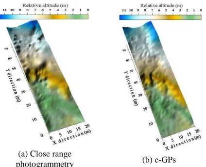
) is 0.7 adopted for imagine matching (Wanek and Wu, 2006).(a) Close range
photogrammetry (b) e-GPs
Figure 6. Construct the DTM at site A with (a) close range photogrammetry and (b) e-GPS
Figure 6 illustrates measured results with close range digital photogrammetry and e-GPS at site A. We got 4995 points at site A using close range digital photogrammetry to calculate the surface area which was 1608.5 m2 (Figure 6a). A total of 3268 points was yielded using e-GPS to calculate surface area which was 1580.9 m2 (Figure 6b). The related error of surface area with close range digital photogrammetry and e-GPS is 1.7%. It revealed that the measurement of surface area with close range digital photogrammetry was acceptable methodology. Travelletti et al. (2012) used a low-cost methodology to monitor the displacement of continuously active landslides from ground-based optical imagines analyzed with a normalized image correlation technique. They found that the camera monitoring allowed characterizing displacements of up to 3 m/day during an acceleration period. Their measured
results were in good agreement with previous knowledge on the landslide kinematics and in very good agreement with benchmark displacements measured by dGPS. Our measured results also revealed that the image systems exhibited the high potential for landslide monitoring.
Type of camera Canon EOS 400D digital camera Effective pixels 10.1 million
Image sensor RGB CMOS 22.2 x 14.8 mm
Image size 3888 x 2592 pixels
Focal length 35 mm
Sensitivity Automation (100~400 iso)
Shutter speed Automation (1/4000~30 sec) Table 1. Characteristics of the camera acquisition systems 3.3 Estimation of Landslide Volume
Matori et al. (2012) applied close range photogrammetric method to derive the DEMs on slope area. Their results found that DEMs with accuracy in elevation interpolation was in centimeters level, and accuracy in volume estimation was less than 0.5%. They also concluded that detection of landslide by using close range photogrammetric method was effective to apply for high risk and inaccessible slope are. After the landslide measurement had been validated with close range photogrammetry and e-GPS at site A, the methodology of close range photogrammetry was applied to measure the volume before and after landslides at site B. Figure 7 presents the DTMs before landslide and after landslide. The cloud points before and after landslides are composed of 2959 and 1237, respectively. The measured results indicated that the surface area and volume before landslide were 413.48 m2 and 2169.22 m3, respectively, while they are 383.19 m2and 1175.06 m3, after landslide. The volume difference between before and after landslides was 994.16 m3. The camera systems present powerful tool to monitor the land sliding region.
(a) Before landslide (b) After landslide Figure 7. Construct the DTM at site B with close range photogrammetry (a) before landslide and (b) after landslide
4. CONCLUSIONS
Close range photogrammetric techniques have been sown to be very useful tools for monitoring landslide in dangerous regions. Such techniques allow is to carry out exhaustive analyses of localization of most damaged areas. In the present study, the
close range digital photogrammetry with DLT method was applied to measure the landslide region in central Taiwan. In order to ascertain the proposal methodologies which have the capability to detect the landslide region, the close range photogrammetric techniques and e-GPS were adopted to measure the landslide region at side A. We found that the relative error for measuring surface area were 1.7%. It demonstrated that the close range digital photogrammetry with DLT method was useful for monitoring at landslide region. This method was then applied to measure the landslide volume at site B before and after landslides. The volume difference between before and after landslides was 994.16 m3.
The limitations of ground-based optical imagines are independent of the acquisition system. They are related to the meteorological and illumination conditions, the ground surface changes, and continuous monitoring through the image systems. These challenges should be more studied to resolve the issues in the future work.
ACKNOWLEDGEMENTS
The work was partially funded by the Minster of Science and Technology, Taiwan, under grant No. MOST 104-2625-M-239-002.
REFERENCES
Abdel-Aziz, Y. I., Karara, H. M., 1971. Direct linear transformation from comparator coordinates into object space coordinates in close range photogrammetry. Proceedings of the ASP/UI Symposium on Close-Range Photogrammetric System, Falls Church, VA, pp. 1-18.
Aguilar, M. A., Aguilar, F. J., Aguera, F., Carvajal, F., 2005. The evaluation of close-range photogrammetry for modelling of mouldboard plough surfaces. Biosystems Engineering, 90(4), pp. 397-407.
Adrian, R., 1991. Particle-image techniques for experimental fluid mechanics. Annual Review of Fluid Mechanics, 23(1), pp. 261-304.
Arias, P., Herraez, J., Lorenzo, H., Ordonez, C., 2005. Control of structural problems in cultural heritage monuments using close-range photogrammetry and computer methods. Computers & Structures, 83(21-22), pp. 1754-1766.
Arias, P., Ordonez, C., Lorenzom H., Herraez, J., Armesto, J., 2007. Low-cost documentation of traditional argo-industrial buildings by close-range photogrammetry. Building and Environment, 42(4), pp. 1817-1827.
Atkinson, K. B., 1996. Close range photogrammetry and machine vision. Whittles Publishing, Scotland.
Brown, L. G., 1992. A survey of image registration techniques.
ACM Computing Surveys, 24(4), pp. 325−376.
Cardenal, J., Mata, E., Perez-Garcia, J. L., Delgado, J., Andex, M. A., Gonzalez, A., Diazde-Teran, J. R. 2008. Close-range digital photogrammetry techniques applied to landslide monitoring. International Archives of Photogrammetry, Remote Sensing and Spatial Information Sciences, 37, Part B8.
Casagli, N., Farina, P., Leva, D., Tarchi, D., 2004. Application of ground-based radar interferometry to monitor an active rock
slide and implication on the emergency management. In: Evans, S. G., Scarascia-Mugnozza, G., Strom, A., Hermanns, R. L. (eds.), Landslides from Massive Rock Slope Failure, Proceedings of NATO Advances Research Workshop on Massive Rock Slope Failure-New Models for Hazard Assessment, Celano, Italy, Springer, Berlin, pp. 351-360. Cooper, M. A.R., Robson, S., 2000. Theory of close range photogrammetry. In: Close Range Photogrammetry and Machine Vision, Whittles, Roseleigh House, Latheronwheel, Caithness, KW56DW, Scotland, UK, pp. 9-50.
Debella-Gilo, M., Kaab, A., 2011. Sub-pixel precision image matching for measuring surface displacements on mass movements using normalized cross-correlation. Remote Sensing of Environment, 115(1), pp. 130-142.
Delacourt, C., Allemand, P., Berthier, E., Raucoules, D., Casson, B., Grandjean, P., Pambrun, C., Varel, E., 2007. Remote-sensing techniques for analysing landslide kinematics: a review. Bulletin de Societe Geologique, 178(2), pp. 89-100. Fraser, C. S., 1993. A resume of some industrial applications of photogrammetry. ISPRS Journal of Photogrammetry and Remote Sensing, 48(3), pp. 12-23.
Fraser, C. S., 1996. Network design, close range photogrammetry and machine vision. In: Atkinson, K. (Ed.), Whittles, Caithness, U.K., pp. 256-279.
Fraser, C. S., 2013. Automatic camera calibration in close range photogrammetry. Photogrammetric Engineering and Remote Sensing, 79(4), pp. 381-388.
Fraser, C. S., Riedel, B., 2000. Monitoring the thermal deformation of steel beams via vision metrology. ISPRS Journal of Photogrammetry and Remote Sensing, 55(4), pp. 268-276. Fujita, I., Muste, M., Kruger, A., 1998. Large-scale particle image velocimetry for flow analysis in hydraulic engineering applications. Journal of Hydraulic Research, 38(3), pp. 397-414.
Greeen, J., Matthews, S., Turanli, T., 2002. Underwater archaeological surveying using PhotoModeler, Virtualmapper: different applications for different problems. International Journal of Numerical Archaeology, 31(2), pp. 283-292. Heritage, G. L., Fuller, I. C., Charlton, M. E., Brewer, P. A., Passmore, D. P., 1998. CDW photogrammetry of low relief fluvial features: accuracy and implications for reach-scale sediment budgeting. Earth Surface Processes and Landforms, 23(13), pp. 1219-1233.
Jiang, R., Jauregui, D. V., White, K., 2008. Close-range photogrammetry applications in bridge measurement: literature review. Measurement, 41(8), pp. 823-834.
Liu, J. W., Jiang, Z. Q., Sun, X., Hu, H., 2012. Integration of close range photogrammetry and structured light scanner for cultural heritage documentation. Advanced Materials Research, 468-471, 1966-1969.
Maas, H. G., Virant, M., Becker, J., Bosemann, W., Gatti, L., Henrichs, A., 2002. Photogrammetric methods for measurements in fluid physics experiments in space. Acta Astronautica, 50(4), pp. 225-231.
Mikhail, E. M., Bethel, J. S., McGlone, J. C., 2001. Introduction to modern photogrammetry. John Wiley and Sons, Inc.
Mills, J. P., Barber, D., 2004. Geomatics techniques for structure surveying. ASCE Journal of Surveying Engineering,
130(2), pp. 56-64.
Matori, A. N., Mokhtar, M. R. M., Cahyono, B. K., Yusof. K. B., 2012. Close-range photogrammetric data for landslide monitoring on slope area. IEEE Colloquium on Humanities Science on Engineering Research, Kata Kinabala, Malaysia. Pesci, A., Baldi, B., Bedin, A., Casula, G., Cenni, N., Fabris, M., Loddo, F., Mora, P., Bacchetti, M., 2004. Digital elevation models for landslide evolution monitoring: application on two areas located in the Reno River Valley (Italy). Annals of Geophysics, 47(4), pp. 1339-1353.
Raffel, M., Willert, C., Kompenhans, J., 1998. Particle image velocimetry: a practical guide. New York, N.Y., Springer. Reinoso, , J. F., Moncayo, M., Barrera, D., 2014. Close-range photogrammetry applied to the documentation of cultural heritage using telescopic and wide-angle lenses. The Imaging Science Journal, 62(7), pp. 387-394.
Sturzenegger, M., Stead, D., 2009. Close-range digital photogrammetry and terrestrial laser scanning for discontinuity characterization on rock cuts. Engineering Geology, 106(3-4), pp. 163-182.
Sheng, L., Gong, Z. B., 2014. A novel mesh subdivision algorithm for dense reconstruction from multi-image based on preliminary model. The Imaging Science Journal, 62(1), pp. 16-26.
Tang, R., Fritsch, D., 2013. Correlation analysis of camera self-calibration in close range photogrammetry. The Photogrammetric Record, 28(141), pp. 86-95.
Travelletti, J., Delacourt, C., Allemand, P., Malet, J. P., Schmittbuhl, J., Toussaint, R., Bastard, M., 2012. Correlation of multi-temporal ground-cased optical imagines for landslide monitoring: application, potential and limitation. ISPRS Journal of Photogrammetry and Remote Sensing, 70, 39-55.
Wanek, J. M., Wu, C. H., 2006. Automated trinocular stereo imaging system for three-dimensional surface wave measurements. Ocean Engineering, 33(5-6), pp. 723-747. Westerweel, J., 1993. Digital particle image velocimetry: theory and application. Delft, Delft University Press.
Yastikli, N., 2007. Documentation of cultural heritage using digital photogrammetry and laser scanning. Journal of Cultural Heritage, 8(4), pp. 423-428.
Yilmaz, H. M., Yakar, M., Gulec, S. A., Dulgerler, O. N., 2007. Importance of digital close-range photogrammetry in documentation of cultural heritage. Journal of Cultural Heritage, 8(4), pp. 428-433.
Yilmaz, H. M., Yakar, M., Yildiz, F., 2008. Documentation of historical caravansaries by digital close range photogrammetry.
Automation in Construction, 17(4), pp. 489-498.
Zitová, B., Flusser, J., 2003. Image registration methods: a survey. Image and Vision Computing, 21(11), pp. 977-1000.