Publication Date: 2015-11-18
Approval Date: 2015-07-17
Posted Date: 2015-06-18
Reference number of this document: Testbed11 Referenceable Grid Harmonization Engineering Reportr1
Reference URL for this document: http://www.opengis.net/doc/PER/t11-referenceable-grid
Category: Public Engineering Report
Editors: Eric Hirschorn, Peter Baumann
OGC Testbed11 Referenceable Grid Harmonization
Engineering Report
Copyright © 2015 Open Geospatial Consortium.
To obtain additional rights of use, visit http://www.opengeospatial.org/legal/.
Warning
This document is not an OGC Standard. This document is an OGC Public Engineering Report created as a deliverable in an OGC Interoperability Initiative and is not an official position of the OGC membership. It is distributed for review and comment. It is subject to change without notice and may not be referred to as an OGC Standard. Further, any OGC Engineering Report should not be referenced as required or mandatory technology in procurements.
Document type: OGC® Engineering Report Document subtype: NA
License Agreement
Permission is hereby granted by the Open Geospatial Consortium, ("Licensor"), free of charge and subject to the terms set forth below, to any person obtaining a copy of this Intellectual Property and any associated documentation, to deal in the Intellectual Property without restriction (except as set forth below), including without limitation the rights to implement, use, copy, modify, merge, publish, distribute, and/or sublicense copies of the Intellectual Property, and to permit persons to whom the Intellectual Property is furnished to do so, provided that all copyright notices on the intellectual property are retained intact and that each person to whom the Intellectual Property is furnished agrees to the terms of this Agreement.
If you modify the Intellectual Property, all copies of the modified Intellectual Property must include, in addition to the above copyright notice, a notice that the Intellectual Property includes modifications that have not been approved or adopted by LICENSOR. THIS LICENSE IS A COPYRIGHT LICENSE ONLY, AND DOES NOT CONVEY ANY RIGHTS UNDER ANY PATENTS THAT MAY BE IN FORCE ANYWHERE IN THE WORLD.
THE INTELLECTUAL PROPERTY IS PROVIDED "AS IS", WITHOUT WARRANTY OF ANY KIND, EXPRESS OR IMPLIED, INCLUDING BUT NOT LIMITED TO THE WARRANTIES OF MERCHANTABILITY, FITNESS FOR A PARTICULAR PURPOSE, AND NONINFRINGEMENT OF THIRD PARTY RIGHTS. THE COPYRIGHT HOLDER OR HOLDERS INCLUDED IN THIS NOTICE DO NOT WARRANT THAT THE FUNCTIONS CONTAINED IN THE INTELLECTUAL PROPERTY WILL MEET YOUR REQUIREMENTS OR THAT THE OPERATION OF THE INTELLECTUAL PROPERTY WILL BE
UNINTERRUPTED OR ERROR FREE. ANY USE OF THE INTELLECTUAL PROPERTY SHALL BE MADE ENTIRELY AT THE USER’S OWN RISK. IN NO EVENT SHALL THE COPYRIGHT HOLDER OR ANY CONTRIBUTOR OF
INTELLECTUAL PROPERTY RIGHTS TO THE INTELLECTUAL PROPERTY BE LIABLE FOR ANY CLAIM, OR ANY DIRECT, SPECIAL, INDIRECT OR CONSEQUENTIAL DAMAGES, OR ANY DAMAGES WHATSOEVER RESULTING FROM ANY ALLEGED INFRINGEMENT OR ANY LOSS OF USE, DATA OR PROFITS, WHETHER IN AN ACTION OF CONTRACT, NEGLIGENCE OR UNDER ANY OTHER LEGAL THEORY, ARISING OUT OF OR IN CONNECTION WITH THE IMPLEMENTATION, USE, COMMERCIALIZATION OR PERFORMANCE OF THIS INTELLECTUAL PROPERTY. This license is effective until terminated. You may terminate it at any time by destroying the Intellectual Property together with all copies in any form. The license will also terminate if you fail to comply with any term or condition of this Agreement. Except as provided in the following sentence, no such termination of this license shall require the termination of any third party end-user sublicense to the Intellectual Property which is in force as of the date of notice of such termination. In addition, should the Intellectual Property, or the operation of the Intellectual Property, infringe, or in LICENSOR’s sole opinion be likely to infringe, any patent, copyright, trademark or other right of a third party, you agree that LICENSOR, in its sole discretion, may terminate this license without any compensation or liability to you, your licensees or any other party. You agree upon termination of any kind to destroy or cause to be destroyed the Intellectual Property together with all copies in any form, whether held by you or by any third party. Except as contained in this notice, the name of LICENSOR or of any other holder of a copyright in all or part of the Intellectual Property shall not be used in advertising or otherwise to promote the sale, use or other dealings in this Intellectual Property without prior written authorization of LICENSOR or such copyright holder. LICENSOR is and shall at all times be the sole entity that may authorize you or any third party to use certification marks, trademarks or other special designations to indicate compliance with any LICENSOR standards or specifications.
This Agreement is governed by the laws of the Commonwealth of Massachusetts. The application to this Agreement of the United Nations Convention on Contracts for the International Sale of Goods is hereby expressly excluded. In the event any provision of this Agreement shall be deemed unenforceable, void or invalid, such provision shall be modified so as to make it valid and enforceable, and as so modified the entire Agreement shall remain in full force and effect. No decision, action or inaction by LICENSOR shall be construed to be a waiver of any rights or remedies available to it.
Contents
Page6.2 A GMLCOV ReferenceableGrid Element that Generalizes Both ReferenceableGridByVectors and ReferenceableGridByArray ... 15
6.2.1 Analysis ... 15
6.2.2 Change Request ... 15
6.3 A GMLCOV ReferenceableGrid Element for Remote Sensing Systems ... 16
6.3.1 Analysis ... 16
6.3.2 Change Request ... 17
6.4 Extend Usability of Coverage Identifiers ... 18
6.4.1 Analysis ... 18
6.4.2 Change Request ... 18
6.5 Integrated Handling of Space/Time and Other Axes ... 18
6.5.1 Analysis ... 18
6.5.2 Change Request ... 20
6.6 GMLCOV Document Name Change ... 21
6.6.1 Analysis ... 21
6.6.2 Change Request ... 22
6.7 Resolve Confusion about Discrete versus Continuous Coverages ... 22
6.7.2 Change Request ... 23
6.8 Additional Requests ... 23
7 Summary ... 24
Annex 1: UML model for coverages ... 26
Annex 2: GMLCOV ReferenceableGridBySensorModel Example of Use ... 31
Abstract
This Engineering Report is a deliverable of the Testbed-11 Urban Climate Resilience (UCR) Thread. The UCR Thread responds to the urgent need to make climate
information and related data readily available for the public and government decision makers to prepare for changes in the Earth’s climate. An important set of a data sources that will play an important role in detecting changes due to climate effects are a wide array of remote imaging systems.
In the most straightforward case, systems collect light reflected from the ground through a 2-dimensional collection grid of CCD sensors, which in turn forward the values meas-ured into an image. When an additional “georeferencing” transformation is available, the position of each grid value can be traced back to the reflection point; in this case, the grid and the associated image are said to be “georeferenceable”. Often, a grid (now seen as a data structure) contains explicit information on how to obtain the location of each grid point (such as grid origin and resolution). Sometimes, though, the georeferencing inform-ation is hidden in complex mathematical models. Methods for obtaining the geolocinform-ation of grid points refer to the techniques described in ISO 19130, such as sensor models, functional fit models, and spatial registration using control points1. In other cases, such as
climate data sets, location is given through the simulation model. A longstanding goal of OGC and supporting organizations is the development of a common standard supporting the “georeferenceable grid” in its full generality.
Note, however, that remote sensing is but one particular application domain for gridded data (an example for a further category being climate data), and 2-D imagery is just a special case (an example for further dimensions being 3-D image timeseries and 4-D weather forecasts). Furthermore, gridded data embed themselves into a larger information category, termed coverages. The term “coverage”, as per ISO 19123 and OGC Abstract Topic 6, includes regular and irregular grids, point clouds, and general meshes. Care has to be taken, therefore, to establish standards that are both general enough to be applicable to the whole category and sufficiently easy in use for every particular special case. After years of effort by government, industry, and academic organizations, a set of OGC standards have arisen that can in-principle be used to process data taken on a georefer-enceable grid. However, specifications have emerged in different places (such as GML 3.2.1, GML 3.3, SensorML 2.0, GMLCOV 1.0, as well as format encodings like GML-JP2 2.0) and with different particular goals in mind; therefore, both harmonization and completion of definitions are required, leading to Change Requests for the OGC coverage definition. Towards this goal, this Engineering Report makes several suggestions.
1 OGC 05-015, “Imagery Metadata”, page 7
Business Value
OGC coverages, building upon GMLCOV 1.0, are heavily used in practice for regularly gridded data in multiple spatio-temporal dimensions and on hundreds of Terabytes2. The
goal of this Engineering Report is to establish a clear-cut, comprehensive definition of spatio-temporal irregular grids. It is expected that industry and government organizations will find great value in the support and use of these OGC standards, leading to a higher level of interoperability in geospatial imagery products and services, as well as further application domains of irregular grids
2 For one example, see: P. Baumann, P. Mazzetti, J. Ungar, R. Barbera, D. Barboni, A. Beccati, L. Bigagli, E. Boldrini,
Keywords
Copyright © 2015 Open Geospatial Consortium. 1
Testbed11 Referenceable Grid Harmonization Engineering
Report
1 Introduction
1.1 Scope
This OGC® document is applicable to OGC® standards addressing referenceable grids, specifically: GMLCOV 1.0.
This OGC® document clarifies and establishes guidelines for software implementations making use of OGC® standards for referenceable grids.
1.2 Document contributor contact points
All questions regarding this document should be directed to the editors or the contributors:
Name Organization
Eric Hirschorn KEYW
Peter Baumann Jacobs University Bremen, rasdaman GmbH Lucio Colaiacomo EUSC SatCen, Spain
1.3 Future work
The Change Requests described in this document will be worked out in detail, and their application to existing OGC standards will be pursued in the OGC Technical Committee. 1.4 Foreword
Attention is drawn to the possibility that some of the elements of this document may be the subject of patent rights. The Open Geospatial Consortium shall not be held respon-sible for identifying any or all such patent rights.
2 References
The following documents are referenced in this document. For dated references, sub-sequent amendments to, or revisions of, any of these publications do not apply. For un-dated references, the latest edition of the normative document referred to applies. OGC 08-131r3, The Specification Model — A Standard for Modular Specifications
OGC 06-121r9, OGC® Web Services Common Standard
OGC 07-011, OpenGIS® Abstract Specification Topic 6: Schema for coverage geometry and functions
OGC 07-036, OpenGIS® Geography Markup Language (GML) Encoding Standard
OGC 07-112r3, GML 3.2.1 change request – Add implementation of ISO 19123 CV_ReferenceableGrid to GML
OGC 09-091r1, GML 3.2.1 change request – Add ReferencedGridByTransformation OGC 10-129r1, OGC® Geography Markup Language (GML) – Extended schemas and
encoding rules (GML 3.3)
OGC 09-146r2, OGC® GML Application Schema - Coverages
OGC 08-085r4, GML in JPEG 2000 (GMLJP2) Encoding Standard Part 1: Core
OGC 12-108, OGC® GML Application Schema – Coverages – JPEG2000 Coverage Encoding Extension
OGC 09-110r4, OGC® WCS 2.0 Interface Standard – Core: Corrigendum
OGC 10-140r1, OGC® Web Coverage Service 2.0 Interface Standard – Earth Observation Application Profile
OGC 11-135, OGC® Name Type Specification – CRSs
OGC 13-102r2, OGC® Name Type Specification – Time and Index Coordinate Reference System Definitions
OGC 12-000, OGC® SensorML: Model and XML Encoding Standard
3 Terms and definitions
3.1 Referenceable grid
As per ISO 19123, “a referenceable grid is associated with a transformation that can be used to convert grid coordinate values to values of coordinates referenced to an external coordinate reference system”.
3.2 Distorted grid
Terminology introduced in this ER, to be used to denote an enumeration of direct posit-ions, such as in an array. In such grid constructposit-ions, there are no built-in constraints that can imply a set of underlying well-defined grid axes, and so such grids often take on a “distorted” appearance. The axis sets of any two distorted grids within a complete grid specification must be disjoint.
4 Conventions
4.1 Abbreviated terms
AP Application Profile
CRS Coordinate Reference System
DWG Domain Working Group
ER Engineering Report
GML Geographical Markup Language
ISO International Organization for Standardization O&M Observations and Measurements
SensorML Sensor Markup Language SWE Sensor Web Enablement SWG Standards Working Group WCS Web Coverage Service
5 ReferenceableGridOverview
5.1 Concepts
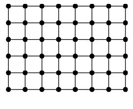
When capturing spatially extended phenomena such as (portions of) the Earth’s surface, many devices collect data in a gridded fashion. Data captured naturally are mapped to multi-dimensional arrays in a programming language sense.
In such an array, the position of each grid point is given by an integer coordinate – the mapping to real-world coordinates we address later. This naturally establishes a neigh-borhood between array points: every point has exactly two neighbors in each dimension, except for those at the “boundary” of the array that have only one. Each grid point locat-ion in the grid we call a “direct positlocat-ion”.
The result is a grid with distance 1 between neighbors. This is good enough to do some calculations (such as computing a vegetation index) or aggregation (such as computing cloud percentage), but it does not yet relate to the “real world”. This is where Coordinate Reference Systems (CRSs) come into play describing the “meaning” of coordinates through a reference system and a datum. Actually, to achieve a unified view, the bare grid itself, with its integer indexes, can be seen as bearing an “Index CRS”3 with a unit of
measure of “1” along each axis and its datum being the origin, i.e.: (0,…,0). Such coverages can be represented by the GML 3.2.1 and GMLCOV 1.0 type Grid4. We call
them “non-referenced – the reason will become obvious below. Figure 1 shows a sample situation with grid points where neighbors are connected through a line.
Figure 1: 2-D grid (GML 3.2.1)
If a coverage is placed on the Earth, the coverage can have an associated Projected CRS (such as those defined by an EPSG code). In such cases, the coverage is said to be referenced (in case of the Earth: georeferenced). Now that a coverage can have two CRSs, a relation needs to be established between both, consisting of a transformation that maps points expressed in one CRS into the other. For our purposes, we classify these according to the type and amount of data needed to describe the transformation.
The next case is a linear dependency between Index and Projected CRS. This is the case, for example, with ortho-rectified imagery and for many types of climate simulation
3 Earlier this was called “Image CRS” in OGC; however, this terminology has been abandoned as coverages tended to
become multidimensional and take data beyond imagery descriptions.
4 Actually, a Grid on principle can also carry projected coordinates. However, due to ambiguities pointed out first by
output data. Due to the linear mapping, neighboring points in the grid have not only constant distances in the Index CRS, but also in the Projected CRS. For some
n-dimensional coverages, this allows the mapping to conveniently be represented by an n-D origin vector, together with a scalar number along each CRS axis, called the resolution of the grid. We call such homogeneous grids “regular”; in GML 3.2.1 and GMLCOV 1.0 such constructs are designated by the term RectifiedGrid. Figure 2 shows the general case of a rectified grid where the spacings are constant, but can themselves be vectors; this allows one to represent mappings belonging to the family of affine transformations.
Figure 2: Regular (“rectified”) 2-D grid (GML 3.2.1)
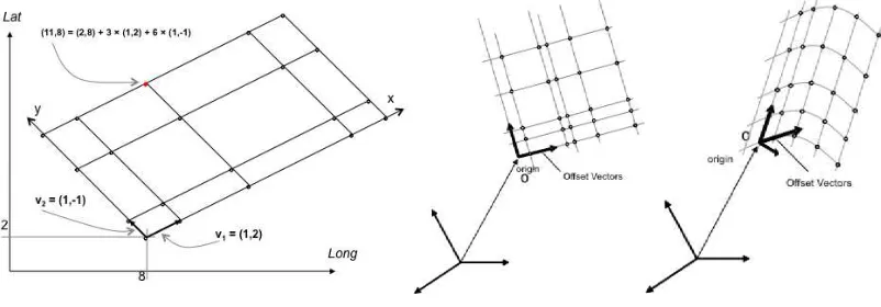
Next, we generalize this to grids that do not have regular spacing. wWe collectively term these “irregular grids”. According to ISO 19123, an irregular grid can result from the application of an associated transformation to an initial simple grid. By means of this transformation, the grid is known as a ‘referenceable grid’. This terminology subsequent-ly has been adopted by GML and the OGC in general.
Figure 3: Irregular 2-D grids (GML 3.3):
rectilinear (left), oblique (center), curved embedding (right)
In such cases, the spacing along each axis is independent from all other axes. In other words, one can advance along one axis in the individual stepping of this particular axis and find the direct points on that axis, regardless of how the spacing along other axes are defined. There are cases where this independence is given up. Figure 4 shows a situation where the direct positions cannot be determined by a linear formula based on each axis. In the end, the coordinate of every direct position needs to be listed explicitly. In terms of data structures, this means that the grid contains an array of coordinates. We call such an irregular grid “distorted”. More specifically: a grid is said to be distorted in a subset of the grid’s axes if the coordinates of the direct points along this axis subset all need to be enumerated individually. For a single axis, this is equivalent to an irregularly spaced grid axis because the points remain on the axis. For a set of m>1 axes combined in a distorted subset (we call such a subset a “distorted grid”), this means that an m-dimensional array is needed to represent the coordinates of direct locations.
Figure 4: “Distorted” 2-D grid (GML 3.3)5
Up to now, cases have been considered where the mapping between Index CRS and Pro-jected CRS has been given by a known formula. Any application can interpret (and, hence, transform) coordinates based on the coverage type and the ancillary information accompanying the grid. Sometimes, however, the transformation is given by a complex algorithm that depends on the type of sensing device and other physical parameters in a way that is too complex to represent in the coverage data structure. This includes the re-alm of OGC SensorML 2.0 Standard. SensorML allows for complex sensor models to be described.
Note that there is a hierarchy of increasing generality among these grid types. If we write “<” for “is less general than”, we obtain the following chain of grid types:
Grid
< Rectified Grid
< Irregular Referenceable Grid < “Distorted” Referenceable Grid < SensorModel Grid
Obviously, a less general grid type can be expressed by a more general variant. For example, a Rectified Grid can be modeled equivalently through a distorted Referenceable Grid by simply computing all the regular grid points and storing them in the distorting array. Clearly, though, this entails quite some inefficiency in terms of the size such a grid (and corresponding coverage) will occupy. Therefore, it makes sense to support the “simpler” grid types. An additional reason is that having classes of increasing complexity allows implementations to decide individually how far they want to go in the support of grid variants.
Finally, sometimes there are more stages of transformation required between the bare grid array and the “real-world” location. Examples include images taken from an air-plane: the CCD device has its own Engineering CRS, which relates the airplane’s CRS, which finally relates to Earth. By concatenating coordinate reference frames, the location of a pixel on Earth can be determined. The GML 3.3 ReferenceableGridByTransformat-ion element was created in part to support this kind of operatReferenceableGridByTransformat-ion (via the gml:Concaten-atedOperation subelement); however, such a transformation cannot be combined with the other mechanisms when constructing a grid. Further, it lacks some integrity constraints that are essential for traversal of such a coverage, most importantly: a rule that demands that coordinates along a timeseries are increasing with each step.
Obviously, several of the above grid types (except the SensorModel variant) are supported in GML 3.3, which specifically adds ReferenceableGridByVectors, ReferenceableGridByArray, and ReferenceableGridByTransformation to the
referenceable grid types (see below for a discussion of the relevant history). Although GML 3.3 extends the grid ecosystem with important cases, as we discuss next, GML
5 Note that the curved connection lines are misleading: they implicitly suggest an interpolation that actually is not
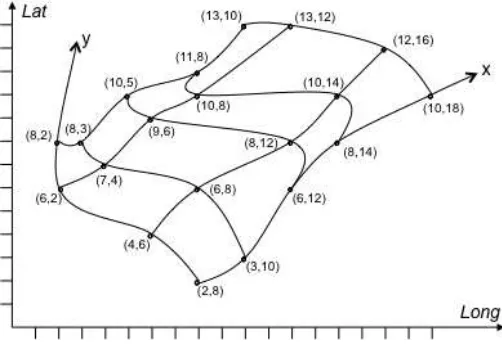
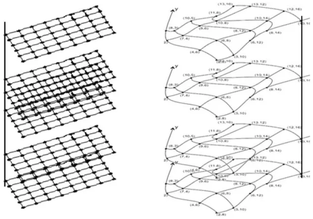
treats a subset of the cases of interest. Specifically, GML 3.3 categorizes at the level of the complete grid. However, as our discussion shows, this categorization should rather be done on the level of the individual axes that are used to construct a grid. If we consider grids from this perspective, we find indeed that all of the above grid types actually define a corresponding set of axis types of increasing complexity: starting from non-referenced, to referenced with equidistant spacing, to variable spacing, to “distorted” axes, to those arising from concatenating transformations, and finally to algorithmically-defined axes. To illustrate this, here is an example that occurs frequently in practice (Figure 5 left, Fig-ure 6 left): “An orthorectified satellite image timeseries datacube has the following axes:
- Lat/Long, which both are regular;
- Time, which is irregular.”
Here is another, more involved, example showcasing a higher-dimensional grid involving several such axis types (Figure 5 right, Figure 6 right; note that the distortion direction upwards is in a spatial direction, whereas the vertical axis denotes time and so is in a different direction – an effect due to the limitations of drawing 4-D spaces in 2-D):
“A timeseries datacube over non-orthorectified satellite imagery has the following axes:
- Lat/Long, which are irregular and “distorted” (and actually need a potentially
complex and opaque georeferencing algorithm to determine concrete grid cell positions, and are equivalently represented by enumeration through a 2-D array);
- Time, which is regular (but obviously independent from Lat/Long and height);
- Height, which is irregular (but obviously independent from Lat/Long and time).”
Figure 6: Sample grids combining regular and irregular axes (left) and irregular axes and “distorted” grids (right); time axis is vertical
Therefore, the unifying conceptual model we propose for grids and gridded coverages is established as follows:
- A coordinate axis (as defined by GML 3.2.1 gml:CoordinateSystemAxisType) is one of the following types:
o Index axis: only integer array coordinates [OGC 13-102r2],
o Referenced axis with constant spacing,
o Referenced axis with variable spacing, or
o Referenced axis with algorithmically given spacing.
- Any subset of at least two “Referenced Axes with variable spacing” in a grid may be combined to form “distorted grids” whereby a distorted grid is defined as follows: for all its axes, the direct position coordinates are given by an explicit enumeration (such as in an array); the axis sets of any two distorted grids within a complete grid specification must be disjoint;
- Over such coordinate axes, a single CRS can be built using the mechanisms defined in the adopted OGC CRS Name Type Specification [OGC 11-135]; - A grid’s overall CRS may derive from a concatenation of several transformations
based on CRSs as above, or from externally defined CRSs (such as EPSG CRSs or Engineering CRSs), as introduced by GML 3.3 ReferenceableGridByTrans-formation;
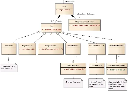
Figure 7 shows a UML model for this concept. In this document, we provide a set of Change Requests to GMLCOV 1.0 with the objective of achieving the model introduced so far and to also break the model down to concrete representation level.
Figure 7: UML model6 for generalized grids
(excerpt from overall coverage model, derived from GMLCOV)
5.2 History
Harmonization issues that involve support of referenceable grids have arisen between related OGC standards that were to a large extent independently developed by OGC working groups for the GML, WCS, and SWE standards, at around the same time period. Despite some collaboration between the relevant working groups, duplicated elements and incomplete implementations resulted. Attempting to spot the origins of this lack of
harmony, we find that all groups contributing coverage work have claimed to ground their efforts on ISO 19123 (which is identical to OGC Abstract Topic 6 [OGC 07-011]). However, as an abstract model, ISO 19123 contains sufficient degrees of freedom to allow diverging, non-interoperable implementations7.
As a result of these groups recognize the potential for diverging implementations. A close collaboration between the WCS SWG (as the lead) and the GML SWG started in 2010 to establish a common OGC coverage model. At the same time collaboration with the SensorML / O&M SWGs began, but at a lesser role. The outcome of this collaboration was adopted in 2012 as OGC’s unified coverage model, documented in “GML 3.2.1 Application Schema – Coverages” [OGC 09-146r2]. This standard was nicknamed GML-COV – a concise, interoperable coverage model whose implementations can be conform-ance tested down to the level of single pixel values. The GMLCOV model extends GML 3.2.1 with a data type description for the coverage cells (“pixels”, “voxels”) called “range type”, so as to give applications a complete set of metadata required for parsing the cov-erage. This definition was adopted from the SWE Common standard of a DataRecord (which is used there for describing the data type of an observation), thereby bridging SWE and non-SWE worlds in OGC. The outcome is the structure depicted by the UML diagram below (Figure 8).
7 Therefore, ISO TC211 WG6 in 2015 has decided to rename 19123 to 19123-1 and accompany it with 19123-2 based
Figure 8: GMLCOV UML model [OGC 09-146r2]
ReferenceableGridCoverage implementation work begins with the adoption of two Change Requests by the OGC members, namely [OGC 07-112r3] and [OGC 09-091r1]. These two Change Requests extend and clarify the coverage definition pertaining to the referenceable grid that, while not implemented in GML 3.2.1, was taken into GMLCOV. While both GML 3.2.1 and GMLCOV 1.0 support the grid coverage types of
GridCoverage and RectifiedGridCoverage, only GMLCOV supports ReferenceableGridCoverage:
● GridCoverage - the original one coverage type, due to some ambiguities not
recommended for georeferenced grids today;
● RectifiedGridCoverage – for equidistant grids, such as ortho-imagery;
● ReferenceableGridCoverage – for various types of irregular grids.
In the GML 3.3 standards document [OGC 10-129r1] section 10.8, the decision of the GML SWG not to include such a definition is described: “[GMLCOV] provides an ele-ment ReferenceableGridCoverage as a GML impleele-mentation of [ISO 19123 eleele-ment] CV_DiscreteGridPointCoverage where the domain is one of the GML implementations of CV_ReferenceableGrid specified in this clause. Since such an element is provided al-ready in that GML application schema for coverages, no new coverage element is provid-ed in this standard.” This decision by the GML SWG removprovid-ed the possibility of harmon-ization issues arising due to duplicate ReferenceableGridCoverage elements.
GMLCOV [OGC 09-146r2] support for ReferenceableGridCoverage includes restrictions on how a ReferenceableGrid element should follow a ReferenceableGridCoverage ele-ment, in the GMLCOV conformance class test A.1.14 “Correct structure of reference-able grid coverage”:
Test purpose: A coverage of ReferenceableGridCoverageshall have a
domain geometry that is a subtype of AbstractReferenceableGrid.
Test method: Check the XML type of the root element of the instance
document under test.
● If type is ReferenceableGridCoverage:
o check whether the document’s domainSet element is in the substitution group of AbstractReferenceableGrid.
● Otherwise, pass test.
development related to GMLCOV ReferenceableGridCoverage must consider and be in compliance with this test, unless a Change Request targets it. However, this reasonable-sounding conformance test is fraught with ambiguity and harmonization implications. The development in GMLCOV of a variety of coverage descriptions has enabled GML-COV to transcend GML in one sense as it establishes clear-cut ways of representing a coverage in other data formats. Fortunately, the usefulness of the GMLCOV coverage de-scriptions, in large part due to their extensibility, has led to a growing list of OGC stand-ards defining such mappings of coverages into formats that include GeoTIFF, JPEG2000, GMLJP2, and NetCDF.
All this work (plus any eventual further work on coverages) was by agreement between WCS SWG and the GML SWG to be merged into the anticipated GML 4.0. However, the GML SWG later on changed plans and instead established GML 3.3 as an extension to GML 3.2.1. This decision was done without involvement of the WCS SWG. This had the consequence that some decisions on how to support ReferenceableGridCoverage definitions in a unified way were left unresolved.
The GML SWG has thus left the development of coverage definitions to GMLCOV. A crucial advance was made when GMLCOV was enhanced to provide a mechanism for extending the coverage definition that made possible the development of application profiles such as MetOcean and Earth Observation (EO). Specifically, by extending the gmlcov:metadata element of the coverage definition with the gmlcov:Extension element, an AP can define an element based on gmlcov:Extension that contains any number of application-specific metadata parameters that can be understood by standard WCS implementations. The GMLCOV 1.0 schema complies with the following statement in its standards document [09-146r2] section 6.1 (Overview section),
“The abstract coverage definition is augmented with an extensible slot for metadata. The intended use is to define concrete metadata structures and their semantics in extensions or application profiles.”
This mechanism is designed to work with WCS 2.0 DescribeCoverage responses, as described in conformance class test A.1.22 in the WCS 2.0 Core standard document [OGC 09-110r4]. The metadata parameters in the GMLCOV coverage are thus incorporated into a wcs:coverageDescription that can be understood by essentially all WCS implementations. An assessment of this mechanism for support of the
ReferenceableGrid for the SensorModel case is of interest.
While the GMLCOV activity also developed a framework for grid descriptions (based on GML 3.2.1, upon which the complete WCS suite developed) related work was
Reference Systems by elements based on gml:Transformation, or alternatively based on gml:ConcatenatedOperation). In the meantime, GMLCOV did not develop any of its own concrete ReferenceableGrid elements from gmlcov:AbstractReferenceableGrid.
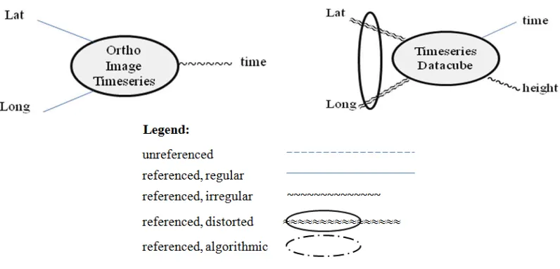
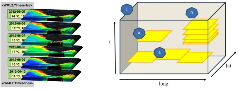
Finally, an independent development started within the Hydrology Domain Working Gorup, where WaterML 2.0 extended its timeseries concept from sequences over scalar values (such as temperature or NOx concentration at some point location) to sequences of images (Figure 9 left) over one location. This resembles a special case of 3-D coverages that very much correspond to the WCS Earth Observation Application Profile [OGC 10-140r1], where stacks of satellite image time slices form a special case of “Stitched Mosaics” (Figure 9 right, case D).
Figure 9: Irregular timeseries in WaterML 2.0 (left) and EO-WCS (right)
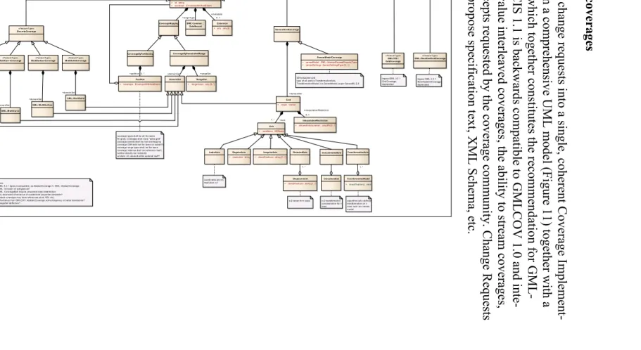
6 GMLCOV Changes Proposed
The following is a list of changes is proposed for GMLCOV with the aim of establishing a comprehensive treatment of gridded coverages. Changes are sketched only (based on the concepts expanded upon in previous sections) and therefore require a detailed elabor-ation on specificelabor-ation text additions (such as additional conformance classes) as well as XML Schema work.
6.1 Harmonization of AbstractReferenceableGrid
6.1.1 Analysis
We have analyzed whether or not a gmlcov:ReferenceableGridCoverage can be followed by one of the 3 GML 3.3 gmlrgrid:ReferenceableGrid elements. The answer appears to be “no”, because of the details in the GMLCOV compliance test A.1.14, which describes the expected structure of ReferenceableGridCoverage. We propose modifying this com-pliance test to remove ambiguities.
Benefits of this CR would include:
The use of native GMLCOV-based ReferenceableGrid elements in the domainSet of gmlcov:ReferenceableGridCoverage would not result in GMLCOV A.1.14 compliance test failure.
Application Profiles based on GMLCOV 1.0 would no longer in effect be re-quired to create their own ReferenceableGrid elements based on
gmlcov:AbstractReferenceableGrid. 6.1.2 Change Request
GMLCOV currently has no concrete ReferenceableGrid elements. Therefore, a Change Request should be formulated to add all concrete ReferenceableGrid elements in GML 3.3 to GMLCOV 1.0 in a coherent fashion while at the same time generalizing them along the concepts described in Section 5.1 (see Change Request in Section 6.2). Recommendation: Update the GMLCOV compliance test A.1.14 to require gmlcov:ReferenceableGridCoverage elements to only use gmlcov:AbstractRefer-enceableGrid -based elements in the domainSet.
Recommendation: Change GMLCOV compliance test A.1.14 to explicitly state the namespace of AbstractReferenceableGrid, which is currently not made explicit, in order to remove ambiguity.
6.2 A GMLCOV ReferenceableGrid Element that Generalizes Both ReferenceableGridByVectors and ReferenceableGridByArray
6.2.1 Analysis
Notably, missing from the three GML 3.3 ReferenceableGrid definitions is a fully general combination of the various grid types (such as a grid where some axes are defined
ByVector and some ByArray). In addition, in some cases grids can only be expressed inefficiently, such as those containing both regular and irregular axes8. Further, to the best knowledge of the authors there is no implementation existing that supports these GML 3.3 types.
6.2.2 Change Request
Recommendation: Add a GeneralGridCoverage structure as presented in Annex 1 to GMLCOV. This structure (which includes and generalizes GML 3.3) allows one to represent and combine all known axis types. All definitions in XML Schema should be self-contained, with reference to GML 3.2.1 only through AbstractCoverage, so that readers of the specification find all coverage-related definitions in one place.
8
For backwards compatibility, GridCoverage and RectifiedGridCoverage should be kept, but deprecated.
6.3 A GMLCOV ReferenceableGrid Element for Remote Sensing Systems
6.3.1 Analysis
A ReferenceableGridCoverage with a SensorML 2.0-based ReferenceableGrid coordinate transformation should typically involve two inputs: a sensor model description containing free variables plus a separate set of variable instantiations. Clearly the sensor model de-scription itself substitutes for the usual domain set of a coverage, which leaves open the question of where to put the model instantiation, i.e., the variable assignments.
One option is to put these into the metadata field of a coverage. However, this has several disadvantages. Firstly, the metadata section is semantically not interpreted when a cover-age is read, so the model is not closed any longer. Secondly, the two ingredients required for deriving direct position coordinates are sitting at different places in a coverage, some-thing which is not elegant or desirable. Therefore, this choice has been abandoned. A second alternative is to put both the sensor model and its instantiation into the domain set. Here a coverage reader can find all location-determining information in one place, which is considered an asset. Of course, the domain set definition has to be extended with a new, radically different alternative, but this is the case for the first option as well. Recommendation: The second option should be detailed into a concrete Change Request adding a SensorML 2.0 -based alternative to the coverage domain.
Figure 10: Relationships between OGC standards using the proposed ReferenceableGridBySensorModel element
6.3.2 Change Request
We propose a ReferenceableGridBySensorModel element for GMLCOV 1.0 that would enable access to the SensorML 2.0 elements SimpleProcess, AggregateProcess, and PhysicalSystem, using a mandatory subelement “sensorModel”.
The element may be processed for instantiation parameters, which can be specified with a dependent SensorML 2.0 –based description using subelement “sensorInstance”.
The following XML Schema snippet defines a ReferenceableGridBySensorModel ele-ment that defines the transformation from the coordinates of the image pixels to ground coordinates:
<element name="ReferenceableGridBySensorModel"
type="gmlcov:ReferenceableGridBySensorModelType" substitutionGroup="gmlcov:AbstractReferenceableGrid"/>
<complexType name="ReferenceableGridBySensorModelType"> <complexContent>
<extension base="gmlcov:AbstractReferenceableGridType"> <sequence>
<element name="sensorModel"
type="sml:AbstractProcessPropertyType" maxOccurs="unbounded"/>
<element name="sensorInstance"
type="sml:AbstractProcessPropertyType" minOccurs="0"
maxOccurs="unbounded"/> </sequence>
</extension> </complexContent> </complexType>
Note that there is no upper limits on the number of sensor models and instances. This is allowed to make it possible to provide alternate sets of sensor models. For example, for a frame camera sensor one may provide a physics-based sensor model or instead a so-called “replacement model” where the details of the sensor are missing. The dependent SensorML document is required to use the sml:typeOf element to specify a primary sensor model document and by doing so keep the connection between the pair of SensorML documents clear.
6.4 Extend Usability of Coverage Identifiers
6.4.1 Analysis
As per GML 3.2.1, coverage identifiers are of type xml:ID which (as per W3C definition) is based on NCName which restricts them essentially to variable names in programming languages (digits, alphabetic characters, underscore).
However, users frequently want to have coverage names that convey some meaning in the context and, therefore, demand punctuation (such as “:”), blanks, and national char-acters. Therefore, the coverage identifier type should be extended to allow for any type of string.
6.4.2 Change Request
Recommendation: Change the coverage identifier type from NCName to xs:string. However, it is unclear at this time how to achieve this in a backwards compatible way and without revising GML 3.2.1.
6.5 Integrated Handling of Space/Time and Other Axes
6.5.1 Analysis
In GML, handling of space and time is separated. This concerns not only the place where coordinates are stored in an XML document, but also affects fundamental modeling; for example, the Coordinate Reference System (CRS) does not include time. Further, GML supports time coordinates in a separate place, but only as a single time dimension – hence, multiple time axes, something repeatedly required by atmospheric and oceanographic modelers, is not possible. Here is the relevant GML 3.2.1 schema: <complexType name="EnvelopeType">
<choice> <sequence>
<element name="lowerCorner" type="gml:DirectPositionType"/> <element name="upperCorner" type="gml:DirectPositionType"/> </sequence>
<element ref="gml:pos" minOccurs="2" maxOccurs="2“/> <element ref="gml:coordinates"/>
</choice>
<attributeGroup ref="gml:SRSReferenceGroup"/> </complexType>
Shortcomings:
CRSs in GML 3.2.1 relate only to the spatial part (such as EPSG) and do not include time axes.
Only one time axis is foreseen by GML.
GMLCOV, therefore, uses a more general approach. The gml:pos elements can be any type of coordinates, be they spatial (horizontal or vertical), temporal, or any other (“ab-stract”) axis. An example for a Lat/Long/time datacube is described by the following GMLCOV snippet9:
<gmlcov:GridCoverage … > <gml:boundedBy>
<gml:Envelope srsName=" http://www.opengis.net/def/crs-compound? 1=http://www.opengis.net/def/crs/EPSG/0/4326& 2=http://www.opengis.net/def/crs/OGC/0/AnsiDate“ axisLabels="Lat Long Time" uomLabels="deg deg sec" srsDimension=“3"> <gml:lowerCorner>1 1 123456890</gml:lowerCorner>
This space/time modeling makes use of a compound CRS as standardized in the OGC CRS Name Type Specification [OGC 11-135]. The value of the srsName attribute is a URI that combines, by concatenation, the Lat and Long axes provided by EPSG 4326 with the time axis provided by AnsiDate; each of those are CRSs in turn, their definition can be obtained by accessing the OGC CRS resolver listening at
http://www.opengis.net/def/. This way, any CRSs and axes can be combined into a new
ad-hoc CRS. WCS allows subsetting on all coordinate axes.
Further attributes in the gml:Envelope are redundant, as the CRSs referenced provide this information. For efficiency reasons, though, some relevant information is provided locally in the coverage, thereby easing the life of applications. These are the list of axis labels (needed, e.g., for subsetting through WCS), the units of measure for each axis, and a count of the number of dimensions this coverage spans. GML elements gml:lowerCorn-er and gml:uppgml:lowerCorn-erCorngml:lowerCorn-er provide the boundary coordinates of the covgml:lowerCorn-erage. Obviously, gml:axisLabels unambiguously specifies coordinate sequence in lower and upper corner coordinates, and gml:srsDimension specifies how many coordinate items the lower and upper corner elements must contain.
While this allows for a concise description of space/time coverages, and even covers the case of multiple time axes, another issue remains: Listing time coordinates only in the unit of measure given (such as seconds since epoch, i.e.: January 1, 1970) is unwieldy. Preferably, a human-readable calendar syntax as given by ISO 8601 should be possible,
9
for example “2015-04-02T14:20+1:00”. However, GML only allows numbers as coord-inates. GML proponents argue that content mixing strings (such as ISO 8601 dates) and numbers can make parsing difficult. However, this difficulty is rather caused by the co-ordinate modeling in the first place: putting structure on the content rather than enclosing atomic values in tags as foreseen by XML.
6.5.2 Change Request
Recommendation: Allow any type and dimensionality of coordinates, by introducing an additional alternative EnvelopeWithAxisExtent that is based on gml:Envelope of GML 3.2.1:
<element name="axisExtent" maxOccurs="unbounded"> <attribute name="axisLabel" type="xs:string">
<attributeGroup ref="gml:SRSReferenceGroup"/> </complexContent>
</complexType>
The following XML snippet is an instance example for use within GMLCOV: <EnvelopeWithCRS srsName="http://www.opengis.net/def/crs-compound? 1=http://www.opengis.net/def/crs/EPSG/0/4326& 2=http://www.opengis.net/def/crs/OGC/0/ansiDate" axisLabels="Lat Long ansiDate" uomLabels="deg deg day" srsDimension="3"> <axisExtent axisLabel=“Lat”>
<lowerBound>1</lowerBound> <upperBound>3</upperBound> </axisExtent>
<axisExtent axisLabel=“Long”> <lowerBound>4</lowerBound> <upperBound>5</upperBound> </axisExtent>
<axisExtent axisLabel=“ansiDate”>
<upperBound>2012-03-11</upperBound > </axisExtent>
</ EnvelopeWithCRS>
This example makes use of the ISO 8601 notation of time. Another alternative (under ex-ploration by the OGC Temporal DWG) is to use terminology defined by some calendar, for example:
<axisExtent axisLabel=“geological”> <lowerBound>Devonian</lowerBound> <upperBound>Cretaceous</upperBound> </axisExtent>
Such an integrated spatio-temporal modeling has several advantages, and in particular supports use cases arising from space/time datacubes:
● allows any coordinates, esp. numbers, strings ● supports use case of multiple time axes ● explicit axis sequencing
● Safe with respect to axis handling ● Simple parsing
Together with a corresponding adaptation of the domainSet handling of coordinate values, this is proposed to become part of GMLCOV 1.1,
Credits: original idea by Max Martinez, discussion contribution by Mathias Mueller and Chris Little; work has been supported by European Union funded projects PublicaMundi
and EarthServer-2.
6.6 GMLCOV Document Name Change
6.6.1 Analysis
The title “GML 3.2.1 Application Schema – Coverages” [OGC 09-146r2] of GMLCOV is historically motivated: At adoption time the document was expected to become part of future GML 4.0. In fact, this naming has caused considerable confusion. First, there is an unwarranted binding of GMLCOV to GML version 3.2.1; consequently, for users it is not clear at all whether GML 3.3 concepts are embraced by GMLCOV, as formally there is a different namespace for GML 3.3. Also, this contradicts the OGC Modular Specification [08-131r3] approach of expressing specification dependencies.
Additionally, GML 4.0 plans have been abandoned meantime, so the main original reason for the naming is not relevant any longer.
Finally, ISO with its adoption of GMLCOV has requested to resolve the unclear title by changing it into something like “coverage implementation model” in the course of adopt-ing it as ISO 19123-2, sequentially next to the abstract model of ISO 19123, which will be known in future as ISO 19123-1.
6.6.2 Change Request
Recommendation: Rename GMLCOV 1.0 to “OGC Coverage Implementation Schema 1.0”, nicknamed CIS. Further, additional changes should be done inside the document to establish coherence:
Rename requirements/conformance class “gml-coverage” to “coverage”;
Adjust phrasing in multipart to allow further Part 1 encodings, such as JSON;
Change of the XML namespace identifier from “gmlcov” to “cis”;
Change Requirement 1 from “Any XML document instantiating a concrete subtype of Coverage …“ to “Any coverage document instantiating a concrete subtype of Coverage …”;
Any further adjustment found necessary.
6.7 Resolve Confusion about Discrete versus Continuous Coverages
6.7.1 Analysis
ISO 19123 distinguishes Discrete Coverages from Grid Coverages. A Discrete Coverage, roughly speaking, can be a point cloud or n-dimensional mesh. Grid Coverages again are subdivided into Discrete Grid Coverages (that cannot be interpolated) and Continuous Grid Coverages (that can be interpolated). From experience, this is a highly confusing situation for users. GML 3.2.1 continues this tradition of separation of discrete from cont-inuous coverages.
Years ago, Arliss Whiteside observed that the difference between discrete and continuous coverages consists only in an added interpolation method: a continuous coverage consists of a discrete coverage plus an interpolation method describing how values between direct positions can be obtained. Consequently, in GMLCOV 1.0 the type AbstractContinuous-CoverageType is only a stub that is not intended for use. Again, this has caused confusion and has led to assumptions of GMLCOV not supporting interpolation.
6.7.2 Change Request
Recommendation: Add an element for interpolation restriction to gmlcov:AbstractDis-creteCoverageType (resp. the new suggested type Grid, see Annex 1) along the following line:
<element name=”interpolationRestriction” type=”InterpolationRestrictionType”> <complexType name="InterpolationRestrictionType">
<complexContent> <sequence>
<element name=”allowedInterpolation” type=”anyURI” minOccurs=”0” maxOccurs=”unbounded”/>
</sequence> </complexContent> </complexType>
Content of the URI element is an URL identifier indicating some interpolation method. Example:
<interpolationRestriction> <allowedInterpolation>
http://www.opengis.net/def/interpolation/OGC/1/nearest-neighbor </allowedInterpolation>
<allowedInterpolation>
http://www.opengis.net/def/interpolation/OGC/1/linear </allowedInterpolation>
<interpolationRestriction> Interpretation is as follows:
If no interpolationRestriction element is present, then any interpolation method is applicable to the coverage on hand.
In presence of an interpolationRestriction element, only those interpolation meth-ods may be meaningfully applied whose identifiers appear in an allowedInterpol-ation element.
6.8 Additional Requests
● An integrated, comprehensive tutorial for Referenceable Grid Coverages should be written for GMLCOV to allow for a compact, comprehensive, and understand-able treatment of the subject. Establishing such a non-normative companion docu-ment for coverage types and their use will contribute to further take-up of OGC standards by users and other standardization bodies (such as ISO).
Recommendation: Add a gridDimension attribute to indicate the geometric dim-ension of the underlying grid. For example, a set of heights on a Lat / Long grid would have (x/y/z) coordinates, hence srsDimension=3, but effectively still remain a plane, hence gridDimension=2.
Knowing both dimension values is important for an application to simplify pars-ing of an incompars-ing coverage, regardless of the encodpars-ing used.
In case both values coincide (such as in non-referenced grids) this distinction is not needed, of course.
● Composite Coverages: stakeholders repeatedly have requested support for nested coverages that are composed of coverages as well. The goal is to allow the treat-ing of them as streat-ingle coverages, i.e. to allow GetCoverage requests on them. To allow this, specific consistency constraints need to hold in order not to violate the coverage definition.
● Referencing of sub-coverages should be done by coverage id, not through direct embedding.
It is recommended, therefore, to extend the coverage definition to support coverages composed from other (same type) coverages.
● Coverages should be extended to allow streaming by (i) supporting an “inter-leaved” presentation and by (ii) allowing “header” data such as gml:boundedBy be empty. The approach should be different from WaterML, which does not support streaming because the GML document never closes (similar difficulties can be expected in a JSON encoding and any other nested format). Rather, refer-encing should be done through coverage id so that each incoming stream item forms a self-contained unit that can be processed independently from other (in particular: later) items.
As the above concept of composite coverages allows one to model this situation, the requirement for streaming is strongly tied to composite coverage support. Further, the coverage descriptions become more general in the sense that stream-ing is not limited to the time axis (as in WaterML), but is possible along any axis (such as height or bathymetry) and even with streams not aligned to any axis at all.
7 Summary
O TransormationModel is a SensorModel as per SensorML20
legacyML21 or grids: coverages shall have "same grid" coverage extents shall be non-overlapping coverage CSR shall be the same (or subset?) coverage range types shall be the same
- GML 3.2.1 types incompatible, as AbstractCoverage != GML::AbstractCoverage - UML: inclusion of subtypes ok?
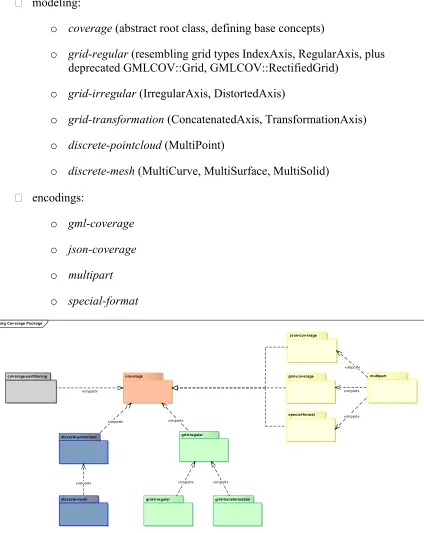
modeling:
o coverage (abstract root class, defining base concepts)
o grid-regular (resembling grid types IndexAxis, RegularAxis, plus
deprecated GMLCOV::Grid, GMLCOV::RectifiedGrid)
o grid-irregular (IrregularAxis, DistortedAxis)
o grid-transformation (ConcatenatedAxis, TransformationAxis)
o discrete-pointcloud (MultiPoint)
o discrete-mesh (MultiCurve, MultiSurface, MultiSolid)
encodings:
o gml-coverage
o json-coverage
o multipart
o special-format
pkg Cov erage Package
cov erage
grid-regular
grid-irregular grid-transformation discrete-pointcloud
discrete-mesh
gml-cov erage multipart
special-format j son-cov erage
cov erage-partitioning
« mport» « mport»
« mport»
« mport»
« mport»
« mport» « mport»
« mport» « mport»
Figure 12: Proposed coverage model modularization (draft)
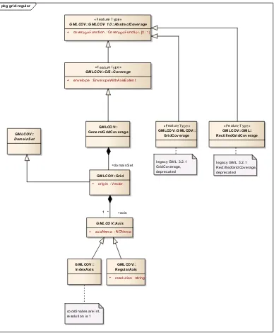
The UML schema in Figure 13 describes class grid-regular essentially consisting of the index grid and regular grid cases, plus the legacy classes GMLCOV::GridCoverage and GMLCOV::RectifiedGridCoverage:
Figure 13: Proposed regular grid model (draft)
GMLCOV:: DistortedAxis
GMLCOV::IrregularAxis
directPositions :stri1..*]
GMLCOV::Displacement
directPositions :stri1..*]
GMLCOV::Axis
axisme :me GMLCOV::Grid
origin :Vector
1* axis
1 *
Figure 15 shows the point cloud model. Essentially, it says: a point cloud coverage is a coverage consisting of domain set, range set, range type, and any set of potential meta-data. Note that the two specializations only facilitate the embedding in the overall cov-erage model and do not constitute any (complicating) variants in the point cloud itself.
class Cov erage Types CIS 1.1 (draft)
GMLCOV 1.0::AbstractCoverage
!eatur"#y$"%
CIS::Coverage
& id :string
& envelope :Envel'$"(ithAxisExtent
!eatur"#y$"%
MultiPointCov erage
!eatur"#y$"%
DiscreteCoverage
RangeSet
& rangeValue :any) ,-./ 3 SWE Common ::
DataRecord
Extension
& any :any),-./3
CoverageMapping
Cov erageByDomainAndRange
DomainSet
GML::MultiPoint
&metadata ,..1 &r
456"#ype
&rangeSet &domainSet
&domainSet
Annex 2: GMLCOV ReferenceableGridBySensorModel Example of Use
The following example XML document defines a referenceable grid coverage10 with a
2D input grid and a SensorML 2.0 –based coordinate transformation of any pixel in the input grid to a 3-D output location. Both of the SensorML documents for the sensor model and corresponding sensor instantiation are given as xlink references for
readability, although the SensorML documents could alternatively be specified in-line. <gmlcov:ReferenceableGridCoverage gml:id="GMLCOV_0"
xmlns="http://www.opengis.net/gml/3.2"
xmlns:gmlcov="http://www.opengis.net/gmlcov/1.0" xmlns:gml="http://www.opengis.net/gml/3.2" xmlns:sml="http://www.opengis.net/sensorml/2.0" xmlns:swe="http://www.opengis.net/swe/2.0" xmlns:xlink="http://www.w3.org/1999/xlink"
xmlns:xsi="http://www.w3.org/2001/XMLSchema-instance" xsi:schemaLocation="http://www.opengis.net/gmlcov/1.0 http://schemas.opengis.net/gmlcov/1.0/gmlcovAll.xsd"> <domainSet>
<gmlcov:ReferenceableGridBySensorModel gml:id="RefGrid_0" dimension="2" srsDimension=”3”> <limits>
</gmlcov:ReferenceableGridBySensorModel> </domainSet>
Here is the sensor model as described in csmFrame.html, which is taken from the
SensorML 2.0 Request For Comments (RFC) package. The document describes a partial set of parameters from the Frame Sensor Model Metadata Profile Supporting Precise Geopositioning (document NGA.SIG.0002_2.1):
10 To keep concerns separated, this still relies on the current GMLCOV structure and does not yet reflect the changes
<sml:SimpleProcess gml:id="CSM_FrameCamera2"
<gml:description>Community Sensor Model (CSM) for Frame Camera</gml:description> <gml:identifier codeSpace="uid">urn:net:swe:process:csmFrameCamera2</gml:identifier> <gml:name>CSM Frame Camera</gml:name>
<sml:inputs> <sml:InputList>
<sml:input name="pixelGridCoordinates">
<swe:Vector referenceFrame="urn:ogc:def:crs:CSM:pixelGridCRS"> <swe:coordinate name="r">
<swe:label>k3</swe:label>
The SensorML 2.0 –based document with the instantiation parameters for the sensor model, myHDCamera.html, is also taken from the SensorML 2.0 RFC:
<sml:SimpleProcess gml:id="myKCM-HD-camera"
An example of an instance of the Community Sensor Model for precise geolocation of the HD UAV-borne video KCM-HD camera
</gml:description>
<gml:identifier codeSpace="uid">urn:myDomain:swe:csm:KCM-HD</gml:identifier> <sml:typeOf xlink:title="urn:net:swe:process:csmFrameCamera2"
xlink:href="http://www.sensors.ws/examples/sensorML-2.0/xml/CSM_FrameCamera2"/> <sml:configuration>
<sml:Settings>
<sml:setValue ref="parameters/csmParams/focalLength">51.5465</sml:setValue>
<sml:setValue ref="parameters/csmParams/focalLength/quality">5.512e-003</sml:setValue>
<sml:setValue ref="parameters/csmParams/pixelGridCharacteristics/rowSpacing">0.0074</sml:setValue> <sml:setValue ref="parameters/csmParams/pixelGridCharacteristics/columnSpacing">0.0074</sml:setValue> <sml:setValue ref="parameters/csmParams/principalPointCoordinates/x0">-0.1608</sml:setValue>
<sml:setValue ref="parameters/csmParams/principalPointCoordinates/x0/quality">4.353e-003</sml:setValue> <sml:setValue ref="parameters/csmParams/principalPointCoordinates/y0">0.0979</sml:setValue>
<sml:setValue ref="parameters/csmParams/principalPointCoordinates/y0/quality">5.059e-003</sml:setValue> <sml:setValue ref="parameters/csmParams/affineDistortionCoefficients/a1">0.0</sml:setValue>
<sml:setValue ref="parameters/csmParams/affineDistortionCoefficients/b1">-4.94883e-025</sml:setValue> <sml:setValue ref="parameters/csmParams/affineDistortionCoefficients/b1/quality">1.419e-016</sml:setValue> <sml:setValue ref="parameters/csmParams/affineDistortionCoefficients/c1">0</sml:setValue>
<sml:setValue ref="parameters/csmParams/affineDistortionCoefficients/a2">0</sml:setValue>
<sml:setValue ref="parameters/csmParams/affineDistortionCoefficients/b2">-1.42380e-025</sml:setValue> <sml:setValue ref="parameters/csmParams/affineDistortionCoefficients/b2/quality">1.419e-016</sml:setValue> <sml:setValue ref="parameters/csmParams/affineDistortionCoefficients/c2">0</sml:setValue>
<sml:setValue ref="parameters/csmParams/radialDistortionCoefficients/k1">3.34076e-005</sml:setValue> <sml:setValue ref="parameters/csmParams/radialDistortionCoefficients/k1/quality">1.036e-006</sml:setValue> <sml:setValue ref="parameters/csmParams/radialDistortionCoefficients/k2">1.64705e-007</sml:setValue> <sml:setValue ref="parameters/csmParams/radialDistortionCoefficients/k2/quality">1.735e-008</sml:setValue> <sml:setValue ref="parameters/csmParams/radialDistortionCoefficients/k3">2.10952e-022</sml:setValue> <sml:setValue ref="parameters/csmParams/radialDistortionCoefficients/k3/quality">1.419e-016</sml:setValue> <sml:setValue ref="parameters/csmParams/decenteringCoefficients/p1">-2.30790e-025</sml:setValue> <sml:setValue ref="parameters/csmParams/decenteringCoefficients/p1/quality">1.419e-016</sml:setValue> <sml:setValue ref="parameters/csmParams/decenteringCoefficients/p2">-4.27963e-025</sml:setValue> <sml:setValue ref="parameters/csmParams/decenteringCoefficients/p2/quality">1.419e-016</sml:setValue> </sml:Settings>
Revision history
Date Release Editor Primary
clauses modified
Description
2015-02-06 0.1.0 Eric Hirschorn All Initial draft and outline 2015-06-08 0.2.0 Peter Baumann All Refinement, further CRs 2015-06-09 0.2.1 Eric Hirschorn All Consolidation of CRs
2015-06-16 1.0.0 All All Final edits, brush-ups