A. Scholtz a, *, C. Kaschwich a, A. Krüger a, K. Kufieta a, P. Schnetter a, C.-S. Wilkens a, T. Krüger a, P. Vörsmann a a Technische Universität Braunschweig, Institute of Aerospace Systems, Hermann-Blenk-Str. 23, 38108 Braunschweig,
Germany - (a.scholtz, c.kaschwich, arne.krueger, karl.kufieta, p.schnetter, c-s.wilkens, thomas.krueger, p.voersmann)@tu-braunschweig.de
KEY WORDS: Carolo P 360, Subvento, Surveillance, UAS, Modular UAV Design, Integrated Navigation, Autopilot
ABSTRACT:
Project SUBVENTO is a joint research project of the research facility Technische Universität Braunschweig and the industry partner BBR - Baudis Bergmann Rösch Verkehrstechnik GmbH in close cooperation with the German Federal Agency for Technical Relief (THW). The Project is funded within the European Regional Development Fund (EFRE) allocated by the European Union. Therein an integrated system for the fast and automated remote detection of heat sources using an infrared camera is being developed. For a precise detection of fires or persons a very accurate navigation system including the algorithms and the hardware is required. Furthermore additional sensors like a multispectral camera applicable in small unmanned aerial vehicles (UAVs) should be implemented. Since the mentioned sensor equipment exceeds the current UAVs’ payload limit, a new Carolo type aircraft with a wingspan of 3.6 m is designed. It has an increased payload capability and an extended flight time. This is possible due to an optimized aerodynamic layout and a high efficient propulsion system.
Das Projekt SUBVENTO ist ein Verbund-Forschungsprojekt der Technischen Universität Braunschweig sowie dem Industriepartner BBR - Baudis Bergmann Rösch Verkehrstechnik GmbH und wird in enger Zusammenarbeit mit dem Deutschen Technischen Hilfswerk (THW) durchgeführt. Das Projekt wird über den Europäischen Fond zur regionalen Entwicklung (EFRE) durch die Europäische Union gefördert. In diesem Projekt wird ein integriertes System zur schnellen und automatischen Detektion von Hitzequellen mittels einer Infrarotkamera entwickelt. Zur genauen Positionsbestimmung der Feuer oder Personen ist ein präzises Navigationssystem, bestehend aus den Navigationsalgorithmen und der verwendeten Hardware, nötig. Des Weiteren sollen zusätzliche für Unbemannte Flugzeuge (UAVs) geeignete Sensoren, wie beispielsweise eine Multispektralkamera integriert werden. Da dieses Sensorpaket die Nutzlast der bisher verfügbaren Flugzeuge der Carolo Familie übersteigt, wird ein neues Muster mit einer Spannweite von 3,6 m entwickelt. Durch eine verbesserte aerodynamische Auslegung und ein effizientes Antriebssystem wird die Flugzeit und Nutzlastkapazität gesteigert.
1. INTRODUCTION
An example for scientific applications with unmanned aerial systems (UASs) is the new project SUBVENTO. The intention of this project is the development of an integrated system for fast and automated remote sensing of heat sources. For this purpose, an infrared camera shall be implemented into a small unmanned aerial vehicle. Using such a system the German Federal Agency for Technical Relief (THW) will be enabled to obtain a fast overview of an operation area. An essential part for the realisation of this system is the automated flying UAS for which a highly integrated and precise autopilot system is necessary. Due to this task new autopilot hardware with increased processing power will be developed. This includes sophisticated navigation algorithms and the data fusion of the GPS and the inertial measurement unit (IMU). With this solution it is possible to find geographic referenced positions of heat sources for example.
The combination of an infrared camera and the additional sensors for detection of hazardous substances exceeds the payload limit of all existing UAVs of the Carolo family of the Technische Universität Braunschweig. For this reason a new type of aircraft, the Carolo P 360, is developed. It shall provide increased payload capacity and allow for simplified integration of additional subsystems and sensor packages, such as an
emergency landing system, while having the same or better endurance and flight performance. To achieve this task a new layout and an optimized aerodynamic design is required. Furthermore the reliability of all additional subsystems must be proven in experiments.
2. INTEGRATED NAVIGATION
2.1 System Architecture
The dimensional limitations on-board a small UAV require the use of sensors based on microelectromechanical systems (MEMS). These are used for the whole Carolo family. The low-cost acceleration and gyroscopic sensors operate at a frequency of 100 Hz but suffer from highly drifting signals. For the compensation of this disadvantage, long-term stable measure-ments of a single-frequency (L1) receiver for the Global Positioning System (GPS) are used. In this way position, velocity and attitude can be determined at the rate of the inertial measurement unit (IMU) with a better precision than with a stand-alone GPS receiver.
Different concepts for the fusion of sensor data as from GPS and IMU measurements exist, see (Farrell & Barth, 1999). The simplest and therefore most common integration is the so called loose coupling. These systems use the position and velocity
information of the GPS to aid the IMU measurements. This approach has the problem that the GPS aiding fails as soon as signals from less than four GPS satellites, which are necessary for a GPS-only navigation solution, are received.
Tight coupling avoids this problem by fusing GPS raw data with IMU measurements. This means, that measurements for pseudo range, delta range, and also carrier phase are used directly in the aiding process. In this way even measurements from one or two satellites have a positive effect on the quality of the navigation solution. On this account a tightly coupled closed-loop system is used for the sensor data fusion. Closed-loop means that the corrected navigation solution from the INS is fed back to the navigation filter to correct the GPS measurements and that the data from the navigation filter is used to correct acceleration and gyroscopic sensor errors (see Figure 1).
Figure 1. Tightly Coupled Closed-Loop System, (NAVCEN, 1996)
2.2 Navigation Hardware
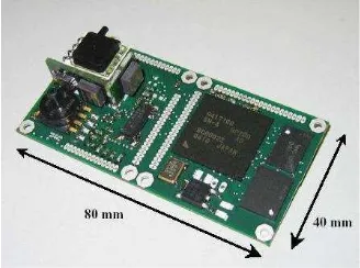
The Carolo type aircraft are equipped with the Miniature Integrated Navigation and Control (MINC) system, see Figure 2. The MINC board incorporates a MEMS inertial measurement unit, sensors for static and total pressure, a GPS receiver and the on-board computer with the dimensions 80 x 40 x 15 mm³. The total mass including an external GPS antenna is 45 g. The measurement block, which is called TrIMU (left part of Figure 2), is fully equipped with three orthogonal angular rate sensors and two dual axis acceleration sensors covering the x-axis twice with different sensitivities.
Figure 2. MINC Autopilot System
2.3 Navigation Filter
The so called Kalman filter, introduced in (Kálmán, 1960), has become a quasi-standard for accomplishing the data fusion of inertial and satellite navigation. The MINC system is based on a time discrete, linear, closed-loop, tightly coupled error state
Kalman filter, see (Winkler & Vörsmann, 2007). The error state architecture allows the estimation of a non-linear process with a linear Kalman filter.
The utilised state vector consists of 17 states for errors in position, velocity, attitude, gyro bias, accelerometer bias, and GPS receiver clock error drift.
The Kalman filter works in two phases - prediction and correction. The prediction is executed at the IMU's measure-ment frequency of 100 Hz. Parallel to the prediction process, the navigation solution is calculated using the IMU measure-ments. These are processed via a so-called strapdown algorithm, which allows the computation of navigation data from body-fixed inertial sensors, see (Kayton & Fried, 1997).
The correction process is started when new GPS measurements have arrived. During this update, the received measurements are processed. The filter uses measured values of pseudo ranges, delta ranges, and time differenced carrier phase corresponding to the number of received satellites. The use of the time differenced carrier phase instead of the carrier phase measurement has the advantage, that it is not necessary to solve the phase ambiguity, see (Farrell, 2001).
For the post-processing of e.g. during flight recorded image or meteorological data it is crucial to have reliable and accurate data of position and attitude available. On-board the aircraft the above mentioned Kalman filter is used for the sensor data fusion of INS and GPS. At each time step the information from all previous measurements is utilised to generate a precise navigation solution. During the post-processing subsequent to the flight measurement data from before and after the gathering of each measurement is available. Thus, during the post-processing it is possible to use information from previous and future measurements for the sensor data fusion and generation of navigation data. For this purpose a so called Rauch-Tung-Striebel (RTS) smoother is used, see (Rauch et al., 1965).
Besides the increase in precision the application of the smoother has several advantages. The effect of the transient oscillation, which can be observed during the beginning of a linear Kalman filter operation, can be reduced due to the use of future data. Additionally it is possible to bridge GPS outages for a certain amount of time during the post-processing.
2.4 Navigation System Performance
lin. Kalman filter RTS smoother
roll angle 0.4 ° 0.3 °
pitch angle 0.4 ° 0.3 °
yaw angle 0.9 ° 0.5 °
Table 1. 1-σ-Accuracy of the Attitude Reference System
In order to determine the accuracy of the navigation algorithm flight experiments have been done using an IMU with fibre optical gyros (type iMAR iVRU-FC) as a reference. The results of the attitude determination are shown in Table 1 with a 1-σ -accuracy. It can be seen that it is possible to calculate a navigation solution of sufficient accuracy using the MEMS based IMU of the MINC autopilot system. Furthermore the results show a significant increase in accuracy due to the use of the RTS smoother.
To increase the processing power and for an easier programming the ILR currently develops a new, autopilot system for unmanned aerial systems. The system consists of a Main Computing Unit (MCU) and the Main Sensor Unit (MSU) which can be extended with numerous Mini Satellite Endpoints (MSE). The principal components, MCU and MSU are plugged together to form a system sized 40 x 70 x 15 mm³, weighting around 50 g including an optional Wifi antenna or 40 g without Wifi. The system offers 10 Servo channels, two USB-Ports, CAN-Bus, GPS and telemetry connections. The power consumption is between 1 Watt to 2 Watts depending on the processor clock rate and an extra of 0.5 Watt for Wifi.
Figure 3. The Autopilot System
3.2 Main Sensor Unit
The Main Sensor Unit abbreviated MSU, which amongst other sensors contains a 9-degree of freedom IMU can be mounted on top of the MCU with a flick of the wrist. The MSU offers angular rates, accelerations and a static as well as a dynamic pressure sensor, furthermore a magnet-field sensor is provided. As such the MSU provides all measurements required for conventional automatic flight control functions. Four customizable potential dividers give the possibility to measure additional analog signals.
3.3 Main Computing Unit
The MCU contains two processors: one smaller processor handles data acquisition and provides the CAN bus interface to remote satellite endpoints. The second, more powerful processor offers a computing power of 800 MHz in a SIMD (Single Instruction Multiple Data) core suitable for complex control-algorithms or even for image processing.
An Ubuntu-realtime operating system running on the main MCU processor allows usage of most plug-and-play devices such as USB-UMTS (GSM) sticks or a webcam. Due to the ability to connect the MCU to the Internet, libraries like openCV or a webserver can be downloaded directly. At the same time the operating system offers a guaranteed maximum realtime-latency of less than 120 µs.
3.4 Satellite Endpoints
Tiny (30 x 30 mm²) extension modules are connected via CAN-Bus to the MCU and can be placed anywhere in the aircraft. The satellite modules offer additional servo and A/D ports for sensors.
Figure 4. Schematic of the System with MSU, MSU and MSE
3.5 Programming
Conceptionally, all interfaces and all processors on the MCU or MSE can be programmed via Simulink-Realtime-Workshop with a one-mouseclick solution. In particular, a software library for every required processor feature and interface, sensor and hardware component is being developed in terms of a Simulink Blockset Library. For example a CAN-Message can be moved via drag-n-drop from the library into the model. As depicted in Figure 5 a MCU program consists of Simulink Blocksets which represent the on-board communication ports and peripherals such as sensors or servos. All remaining auto pilot functions are also implemented using Simulink Blocksets.
Figure 5. Functions Test Program of the MCU
4. THE NEW CAROLO P 360
4.1 Current Aircraft
Since 2001 micro and mini unmanned aircraft are developed at the Institute of Aerospace Systems. The latest of the Carolo family is the one-engined Carolo P 200 (see Figure 6) and the twin-engined Carolo T 200 with a wingspan of 2 m and a maximum take-off weight of 7 kg including 1.5 kg of payload.
The maximum endurance is more than one hour at a cruising speed of 22 m/s. These UASs are typically used for remote sensing applications (Krüger et al., 2010) and for meteorological measurements in meteorological mini aerial vehicle (M²AV) configuration.
4.2 Aircraft Concept
The all new Carolo P 360 further increases the payload limit and enhances the handling on the ground. Due to its modular design a convenient pack size and transportability are achieved. The system is fast reassembled with a minimum of required tools. The P 360 is able to carry an emergency landing system and an adaptive jettisonable undercarriage. The main technical design restrictions are listed in Table 2.
Table 2. Design Restrictions of the Carolo P 360 (Scholtz, 2009)
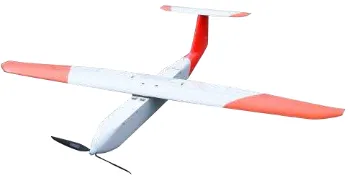
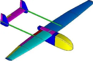
The restriction to a smaller transport size compared to the Carolo P 200 makes a modular aircraft concept necessary. The UAV should be able to transport a meteorological sensor package for turbulence and wind measurements. For this payload, a free airflow from the front is required, which leads to a twin engine or a pusher configuration. A single engine solution is preferred, because of the higher efficiency. The result of the requirements is a conventional aircraft with a centre payload and engine part, a wing with a moderate aspect ratio and two tailbooms with standard tail (Figure 7).
Figure 7. Concept of the new Carolo P 360
An additional requirement is the fast and easy exchange of the payload. This is especially important for the use under ever changing requirements in the academic domain. Therefore a modular payload bay is developed. The whole fuselage front is removable and can be exchanged within few minutes. This also could be interesting for other customers, which like to design their own payload bay. Just the mounting points, the delivered connector for energy and communication with the autopilot system and the moment around this frame to keep the centre of gravity are defined. Figure 8 shows modular payload bays
The most-widely used meteorological sensor package is calibrated for an airspeed of 22 m/s. For this reason, this is the design velocity of the Carolo P 360. It was planned from the beginning of this project to design an aircraft with the possibility to optimize the aerodynamic wing configuration for all existing values of the lift coefficient CL. The wing is therefore equipped with 3 flaps for each side. In this way, it is possible to adjust the circulation distribution for every speed close to the optimal elliptic distribution. The reason for this is that the drag coefficient CD (Eqn. 1) is minimized, which is influenced by the minimum drag coefficient CD0, the induced drag coefficient CDI and the parasite drag coefficient CDP.
DP reach values between 0 < e ≤ 1. The aspect ratio AR is a design parameter and depends on the maximum wing span and the
An additional advantage of the flaps is their dual use as striking airbrake, which reduces the required size of the landing field. The local lift coefficient distribution is also very important, because it gives an impression of the aircrafts handling. Therefore the local lift coefficient, which is predominantly influenced by the wing shape and the airfoil loft, should be nearly constant in the centre wing area and decrease smoothly towards the wing tip. With such a distribution the UAV is still controllable at stalling conditions. Figure 9 shows the diagram for the design velocity and an aircraft weight of 22 kg. Therein it is perceivable, that the local lift coefficient homogenously disturbed along the inner wing area. The curve decreases at the outer 20 % of the wingspan only. This indicates a docile stall behaviour.
Parameter value
maximum take-off weight 25 kg
maximum payload mass 2.5 kg
operation temperature -20°C to +45°C
transport size longest part < 1.6 m
Endurance electric 45 min, combustion 2 h
cruising speed 20 - 30 m/s
maximum wind speed 15 m/s
maximum assembly time 15 minutes
Figure 9. Distribution of Local Lift Coefficient with XFLR5 (Drela & Youngren, 2003)
The choice of the airfoil loft is also very important to increase the flight performance. The airfoils must fulfil different tasks. They have to work efficiently with flaps, provide a very high maximum lift coefficient and a smooth stalling behaviour. The airfoil family HQ-W fits these constraints very well and is chosen for the new Carolo P 360. The combination of this airfoil loft and the accurate wing shape design delivers a maximum simulated glide ratio of 32 for a trimmed configuration at a velocity of 25 m/s. In this simulation only the aerodynamic surfaces where used. In first flight experiments a stationary decent is performed. The altitude H (blue curve) and airspeed Vx (red curve) over the time are shown in Figure 10.
Figure 10. Diagram of In-Flight Measurement of Altitude and Airspeed
The functions of the linear regression for the altitude (Eqn. 3) and airspeed (Eqn. 4) are as follows:
m
36
,
497
m/s
92
.
1
t
H
(3)m/s
04
,
24
m/s²
5
5
E
t
V
x (4)
V
H
E
x (5)Using equation 5 the resulting glide ratio during this flight is calculated to 12.5, which is much lower than the theoretical value. The reason for this is the additional drag of the fuselage
including landing gear, propeller and the tailbooms. Typical values for this type of aircraft are between 10 and 12, so that this result represents the good aerodynamic efficiency of the P 360. During the next month the aircraft flight performance will be quantified with more detailed measurements including energy consumption.
5. APPLICATIONS
5.1 Project ANDROMEDA
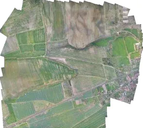
A typical application of our previous UAS, which was developed during the project ANDROMEDA, is to take aerial photographs created by an automated flying mini aerial vehicle (MAV). These photographs are available immediately after the flight and can be inserted into a geographic reference frame. A result of this flights and postprocessings is depicted in Figure 11, which shows a rectified picture mosaic composed of 250 photographs.
Figure 11. A ANDROMEDA 250 Photograph Mosaic (Krüger et al., 2010)
5.2 Project SUBVENTO
This knowledge is further used in the project SUBVENTO, which is the first application of the new Carolo P360 drone. The main task of this project is autonomous fire recognition and surveillance. Recording and observing selected fire parameters and communicating them to the designated fire departement offers an advantage in controlling wildfires. Therefore the drone is equipped with an MIRICLE KS 110 K infrared camera (see Table 3). Its primary component is a micro-bolometer array which is capable of measuring the temperature of an object due to the change of electrical resistance that is generated by the received thermal energy of that object. The captured video stream is transmitted to the ground control station, where it is processed.
parameter value
focal length 14.95 mm
aperture f / 1.3
horizontal view hfov = 35.6° vertical view vfov = 27.1°
array size 384 x 288
detector alpha silicon bolometer spectral range 8 - 12 µm
consumption max. 3.5 W
power supply 3.3 - 5 V
weight 200 g
5.3 Further Applications
In addition to the thermal camera mentioned before the first P 360 delivered to a customer is equipped with a 12 channel multispectral camera Mini MCA (see Figure 12) and a payload computer for image storage and synchronisation of both cameras.
Figure 12. Tetracam Mini MCA 12
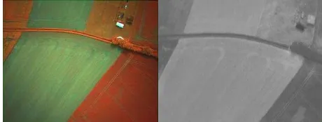
This aircraft is used by the Leibniz Centre for Agricultural Landscape Research (ZALF), Müncheberg. Figure 13 shows two pictures taken during a test flight. One false colour photo-graph made of a combination of three channels, and a thermal image. Differences in the image section are caused by different opening angels of both cameras.
Figure 13. In-Flight Multispectral and Thermal Images
6. CONCLUSION
The all new aircraft family Carolo P 360 had to be developed to increase the payload and flight performance to a new level. This UAV is currently equipped with the MINC autopilot system. In the near future, the new autopilot system presented in section 3 will be implemented to increase the processing power and to offer a much easier programming. This in combination with elaborated navigation algorithms will deliver a highly precise guidance system, suitable for geo-referencing payload information in flight. As typical payloads the used infrared camera as detector for heat sources and a multispectral camera for research purposes are presented. Furthermore, the optimized aerodynamic design of the aircraft is presented which lead to an UAV with convenient handling characteristics in the air as well as on the ground. The combined efforts are necessary to achieve the requirements of the upcoming tasks for the use as a fire detection aircraft.
REFERENCES
Farrell, J. L. and Barth, M., 1999. The Global Positioning System and Inertial Navigation. McGraw-Hill, New York, USA.
Farrell, J. L., 2001. Carrier Phase Procssing Without Integers. Proceedings of Institute of Navigation 57th Annual Meeting/CIGTF 20th Biennial Guidance Test Sympoisum, Albuquerque, New Mexico, USA, pp. 423-428.
Kálmán, R. E., 1960. A New Approach to Linear Filtering and Prediction Problems. Transaction of SME – Journal of Basic Engineering, 82(2), pp. 35-45.
Kayton, M. and Fried, W. R., 1997. Avionics Navigation Systems. Second Edition, John Wiley & Sons, Inc., New York, USA.
NAVCEN, 1996. NAVSTAR GPS User Equipment Introduction, United States Coast Guard Navigation Center, www.navcen.uscg.gov/pubs/gps/gpsuser/gpsuser.pdf (accessed 19 Jul. 2011)
Rauch, H. E., Tung, F., Striebel, C. T., 1965. Maximum Likelihood Estimates of Linear Dynamic Systems. AIAA Journal, 3(8), pp. 1445-1450.
Winkler, S. and Vörsmann, P., 2007. Multi-Sensor Data Fusion for Small Autonomous Unmanned Aircraft. European Journal of Navigation, 5(2), pp. 32-41.
Scholtz, A., 2009. Design and Construction of a UAV-Prototype with Emergency Landing System. Diploma Thesis F 0828 D, Institute of Aerospace Systems, TU Braunschweig
Drela, M., Youngren, H., 2003. XFLR5 Aerodynamic Layout Program, Massachusetts Institute of Technology, USA, http://xflr5.sourceforge.net/xflr5.htm (accessed 12 May 2008)
Krüger, T., Wilkens, C.-S., Reinhold, M., Selsam, P., Böhm, B., Vörsmann, P., 2010. Ergebnisse des ANDROMEDA-Projektes - Automatische Luftbildgewinnung mit Unbemannten Klein-flugzeugen. Deutscher Luft- und Raumfahrtkongress, Paper ID 161314
ACKNOWLEDGMENTS
Project SUBVENTO is funded within the European Regional Development Fund (EFRE) allocated by the European Union. Participating institutions of project SUBVENTO are the research facility Institute of Aerospace Systems of Technische Universität Braunschweig and the industry partner BBR - Baudis Bergmann Rösch Verkehrs-technik GmbH in close cooperation with the German Federal Agency for Technical Relief (THW).