PREPARATION OF THE DIGITAL ELEVATION MODEL FOR ORTHOPHOTO CR
PRODUCTION
Z. Švec a, K. Pavelkaa
a Czech Technical University in Prague, Faculty of Civil Engineering, Thákurova 7, Prague 6, 166 2ř, Czech Republic - [email protected]
Commission III, WG III/1
KEY WORDS: Airborne Laser Scanning, Digital Elevation Model, Orthorectification, Surface Modelling, True Orthophoto
ABSTRACT:
The Orthophoto CR is produced in co-operation with the Land Survey Office and the Military Geographical and Hydrometeorological Office. The product serves to ensure a defence of the state, integrated crisis management, civilian tasks in support of the state administration and the local self-government of the Czech Republic as well. It covers the whole area of the Republic and for ensuring its up-to-datedness is reproduced in the biennial period. As the project is countrywide, it keeps the project within the same parameters in urban and rural areas as well. Due to economic reasons it can´t be produced as a true ortophoto because it requires large side and forward overlaps of the aerial photographs and a preparation of the digital surface model instead of the digital terrain model. Use of DTM without some objects of DSM for orthogonalization purposes cause undesirable image deformations in the Orthophoto. There are a few data sets available for forming a suitable elevation model. The principal source should represent DTMs made from data acquired by the airborne laser scanning of the entire area of the Czech Republic that was carried out in the years 2009-2013, the DMR4G in the grid form and the DMR5G in TIN form respectively. It can be replenished by some vector objects (bridges, dams, etc.) taken from the geographic base data of the Czech Republic or obtained by new stereo plotting. It has to be taken into account that the option of applying DSM made from image correlation is also available. The article focuses on the possibilities of DTM supplement for ortogonalization. It looks back to the recent transition from grid to hybrid elevation models, problems that occurred, its solution and getting some practical remarks. Afterwards it assesses the current state and deals with the options for updating the model. Some accuracy analysis are included.
1. INTRODUCTION
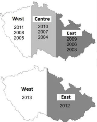
Since 2003, every year the Czech Geodetic and Cadastral Office (ČÚZK) announces public a tender for aerial survey photos of one of the three (see Fig 1.) regions (East, Central, West), Czech Republic (from r. 2012 in two zones only). Aerial survey photos process Surveying Department of Land Survey Office in Pardubice (2/3 of the territory, the southern part) and the Military Geography and Hydrometeorology Office (VGHMÚ ) Dobruška (1/3 of the territory, the northern part). Captured photographs are used primarily for creating periodic orthophotos of the Czech Republic (CR) and also for evaluating stereophotogrammetric changes and a more accurate definition of selected elements such as the actualization of contour altimetry model of the Fundamental Base of Geographic Data (ZABAGED). During the realization of periodic photography of the Czech Republic several parameters have been changed (see Tab. 1).
Figure 1: Aerial mapping periods and parts, the Czech Republic
Table 1. Parameter of aerial survey photography for the creation orthophotos of the Czech Republic (CR)
Period Camera Radiometric resolution Pixel size [m] Scale of survey photos Photographing period
2003–2008 analogue 3 x 8 bits (RGB) 0,5 1 : 23 000 3 years
2009 analogue 3 x 8 bits (RGB) 0,25 1 : 18 000 3 years
2010–2011 digital 3 x 8 bits (RGB) 0,25 1 : 32 000 3 years
since 2012 digital 3 x 8 bits (RGB) 0,25 1 : 32 000 2 years
The product “Orthophoto of the CR” is georeferenced in coordinate system S-JTSK and then is distributed by the Land Survey Office in map sheets of the State Map 1: 5,000. The main users of Orthophotos are the Czech Office for Surveying, Mapping and Cadastre and Ministry of Defence, where “Ortofoto of the CR” is used as a primary source for updating departmental databases, geographic information, and updating and creating state map series (Schickler, 1998). Other users are mainly the Ministry of Agriculture (the basis for the evaluation of basic production units in the system LPIS for agricultural parcel identification, next use in forestry and water management), Ministry of Environment (registration of special interest elements of nature protection in geographic information systems), provincial and municipal local authorities (an important basis for land use planning and designing).Since 2009, the Orthophoto of the CR is defined as one of the basic geographic products in the Czech Republic, published under the rules of INSPIRE in the European geographic infrastructure. For a variety of applications, the absolute positional accuracy of orthophotos is crucial. The following examples may be mentioned:
detection of gross and systematic errors of cadastral maps using their drawings overlap with orthophoto (this especially applies for digitized cadastral maps with risk of systematic shift of entire blocks of parcels)
the use of orthophotos as a basis for designing comprehensive land consolidation,
use as one of the layers of Digital Maps of Public Administration,
basis for digital processing of the territorial plan,
layering of specialized geographic information systems, which are used by construction authorities, Integrated Rescue System and others.
Georeferencing has the biggest influence on the absolute orthophoto positional accuracy quality (selection the number and distribution of control points, calculation of the elements of exterior orientation by the digital automatic aerotriangulation), furthers the parameters of aerial photography and the accuracy of the digital elevation model used for the orthogonalization. All these factors have evolved considerably due to significant changes in 2010. It was therefore necessary to carry out a comprehensive research or survey, resulting in a realistic estimation of the absolute positional accuracy of the “Orthophoto of the CR” created in 2010 and 2011 (for Central and West zones).
2. CREATING OF THE “ORTOPHOTO OF THE CR” AFTER 2010
2.1 Digital aerial survey photographing with VexcelUltraCam aerial camera
Since 2010, specialized firms supply to the Land Survey Office digital aerial photos taken by VexcelUltraCam X (136 megapixels) and VexcelUltraCamXp (196 megapixels) cameras. A high geometric resolution in the panchromatic range was achieved using a composition of nine sub-images. During software image processing, records of each sub images are transformed into the final image using connecting points automatically searched in overlapped areas. UltraMap processing software was used to search for connecting points of the cross correlation algorithm with an accuracy of 0.1 pixel. In the course of the primary image processing of the subimages, various cameras lens distortion was removed, such as local anomalies of geometric images (using parameters from the original calibration
camera protocols). Determining elements of internal orientation of individual cameras, the company Vexcel performs in the laboratory using a spatial calibration field. All elements (focal length, position of the principal image point and Lens Distortion) are determined with a standard deviation of 2 microns. To ensure the correct elements of internal orientation, calibration valid up to one year is required. In compliance with the prescribed procedure for processing, the geometrical quality of the supplied aerial survey photos practically does not affect the accuracy of created orthophoto.
2.2 Georeferencing of aerial survey photos
Georeferencing of aerial photographs consists of determining the elements of external orientation at moment of their acquisition. For each photograph, these elements consist of three coordinates of projection centre (X0, Y0, H0) in a positional and height reference system (in our case the Czech coordinates system S-JTSK and the Baltic altitude system BPV), and three angled elements of image rotation (ω, φ, κ) linked to the axes of these systems. After the introduction of the INS for civilian use, which was recorded during a survey flight to approximate external orientation elements, the following technological processes were used in photogrammetry:
direct georeferencing - using elements of external orientation of the apparatus INS (GNSS / IMU) - this method is the least accurate, in addition to random errors in the results of photogrammetric evaluation large systematic errors could be present,
the calculation of the automatic (digital) aerotriangulation (AAT) with a minimal default number of control points - this procedure delivers more accurate measurement based on on-board INS devices, but does not eliminate systematic errors and controlling of achieved absolute precision of external orientation elements,
the calculation of AAT with an optimum amount of default control points in a suitable configuration (minimum 1 point to 40 km2), where some control points are not included in the calculation of the AAT, but they are used to objective assessment of absolute positional accuracy achieved in the corresponding block of AAT.
Georeferencing of aerial photographs for the creation of the product “Ortofoto of the Czech Republic” is strictly used process ad c) guaranteeing the highest precision and control determining of exterior orientation elements. For the calculation of AAT in the standard block, dimensions of 40 x 50 km around 50 default control points are used.
2.3 Ortogonalization of aerial survey photos
Since 2010 the Land Surveying Office and VGHMÚ has been using for the orthogonalization of aerial survey photographs the recently created digital terrain model of the Czech Republic , 4th generation (4G DMR); it was generated from airborne laser scanning created from 2009-2013.The production technology and accuracy characteristics of the model are described in detail in Control field measurements that showed that complete model mean elevation error reached mH = 0.07 m to 0.34 m, depending on the type of surface and land cover. The maximum residual radial displacements caused by inaccuracy of the digital terrain model in the corners of ortogonalized photos has been occurred. Their size can be determined using the following equation:
�� [�] = � [�] . �� �2 (1)
Where ΔH is the absolute elevation error of the digital terrain model and α is camera´s maximal viewing angle. At maximum viewing angle UltraCam X and UltraCamXp cameras (63.6°) shift in corner of the orthogonalised photos can reach 0.62 ΔH. Given the 60% longitudinal and 25% lateral overlap of aerial survey photos for the resulting mosaic of orthophotos only the central part of the image can be used (specifically about 40% in the flight direction and 75% across the flight direction). The maximum residual radial displacement in such a defined part of the image then reaches maximally 0.41 ΔH.
3. EXPLORATION OF ABSOLUTE POSITIONAL ACCURACY OF THE “ORTHOPHOTO OF THE CR”
FROM PERIOD 2010-11
Absolute positional orthophoto accuracy expresses its cumulative effects of systematic and random errors. Its values are derived from the coordinate’s differences of check points measured geodetically with high accuracy (their coordinates are considered as "correct") and the coordinates of the identical points on the orthophoto obtained by auto guiding of cursor on the georeferenced orthophoto.
3.1 Selecting of check points
To obtain a credible results of checkpoints several sources were used:
Points with mean coordinate error of mxy<0.14 m selected by superimposition of digital cadastral maps and orthophotos of four cadastral areas in city of Pilsen (it was mainly the corners of buildings). From original 451 points they were evaluated 301 (due to a different configuration of images - on images from 2011 some checkpoints used in 2008 were invisible or poorly identifiable).
Points measured by GNSS technology (using RTK) with a mean coordinate error mxy<0.14 meters (electric pylons heels, middle of ameliorative controlling shafts, corners of buildings, etc.). The accuracy of accepted points being characterized by mentioned mXY, but due the used modern and accurate GNSS technology can be assumed mxy ≈ 0.02 m. The same applies for other points measured by modern GNSS. Points are spread out in 10 cadastral areas in Middle and West zones. From original 323 points measured in 2006 only 240 were evaluated. Trigonometry points and net densification points indicated by
white crosses, originally used as a default ground control points or checkpoints in the calculation of AAT. Checkpoints constitute about 10% points, which also applies for other sets of points used in AAT. Points evenly cover the southern part of the territory (2/3 of the area) zones Centre (375 points) and West (292 points).
Signalized points newly measured by GNSS technology with a mean coordinate error mxy<0.14 m; originally they were used as default ground control or checkpoints in the calculation of AAT. 95 points in the Middle of the West zone has been measured.
Naturally identifiable points (road markings, road surface interface, etc.), newly measured by GNSS technology, with a mean coordinate error mxy<0.14 m, originally used as a default or ground control checkpoints for AAT.
122 points have been measured, which evenly covering the northern part of the West zone. When using the default control points for analysis accuracy, we cannot talk about the “absolute positional accuracy” of the survey. These points have already formed the "skeleton" of calculating AAT and therefore can be affected by the error of external orientation elements determining only minimally. Results obtained on these points can be
understood as the sum of all the other errors, especially the influence of inaccuracies in the DTM. The advantage of their use, however, consists in the fact that they uniformly cover all computing blocks and (without additional measurements in the field) it is possible because of their analysis to obtain general information from the whole of the area. The geometric interpretation quality of detailed points is mainly dependent on the resolution orthophotos (the size of the picture element (pixel) in the area and sharpness). They used uniquely identifiable points (mean error guiding mp ≈ 0.7 pixel). Therefore, the whole set of checkpoints assume mp ≤ 0.7 pixel (the Orthophoto of the CR mp ≤ 0.1Ř m. At all checkpoints, coordinate differences ΔY, ΔX (between the values determined from orthophotos and geodetic measurements) and statistical indicators have been calculated. Coordinate differences in all controlled files evaluated in 2012 showed normal distribution. From a total of 541 checkpoints, coordinate differences exceeded the value of one meter in only one case. There was no significant systematic error demonstrated, and the value of systematic errors in most cases did not exceed 0.1 meters. There was a significant reduction of standard coordinate errors in The Orthophoto of the CR occurred in digital aerial images with a geometric resolution of 0.25 meters (on 34% compared to the test orthophoto with resolution of 0.25 m from the test site imaging on analogue film in 2008 (see Tab. 2).
This fact is confirmed in Tab. 3, summarizing the results of testing the absolute positional accuracy of the Orthophoto of the CR, carried out from digital aerial photographs taken in 2010 and 2011 in the 10 test cadastral areas. The average value of standard coordinate error reaches 0.19 m, corresponding to 0.8 pixel size orthophoto.
Until 2009 (inclusive), for orthogonalization of aerial photographs, a digital elevation model of the relief in the form of a 10 meter grid altitude points was derived from altimetry of the ZABAGED®. Since 2010 it has already been used with a more accurate DMR 4G as a 5-meter grid data derived from airborne laser scanning (Tab. 4).
In order to further the verification of the absolute positional accuracy of the Orthophoto of the CR 90, new checkpoints in the eastern half of the Czech Republic were newly measured in November 2012 by the Land Survey Office. Points were measured by GNSS technology - RTK with mxy<0.04 m. Coordinates of their images on the orthophoto were measured by cursor pointing independently by two Land Survey Office employees. Results of the analysis (see Tab. 5) demonstrate the very high absolute positional accuracy of the product in the eastern half of the Czech Republic and confirmed by the results achieved by the previous analyses of accuracy.
4. IMPROVEMENT OF ORTHOPHOTO
Orthorectification of aerial photographs comprise the process of the elimination of geometrical deformations caused by the central projection and vertical distances of terrain via digital elevation model. Until 2010, DTM derived from the digital terrain model of the Fundamental Base of Geographic Data of the Czech Republic, in the grid 10 x 10 m, was applied for orthorectification. Since 2010, a much more precise product processed from airborne laser scanning (DMR 4G) has been available. Therefore, urgent demands for the replenished DMR 4G have arisen. There are 2 forms of the model. The first one, known as the digital terrain model (DTM) represents the earth surface made by natural forces without any object and vegetation on it, and it is used for “classic” orthophoto production. Conversely, the Digital surface model (DSM) contains moreover
upper superficies of all objects on it (roofs, vegetation, etc.) and it serves as true orthophoto generation. Aerial photographs capture terrain relief inclusive of all objects in the DSM at the moment of the exposure. So, during a “classic” orthophoto interpretation, we have to mind that all objects out of the DTM (except of elements in nadir) are projected with position errors (e.g. corner of vertical wall would have different position in the roof level than in the ground level). As the correct projection of some these components are required, it has to be replenished into DTM (Rau;Chen, 2002; Amhar et al., 1998, Faltynova et al., 2013).
5. DMR 4G
Firstly, acquired data was processed to the point cloud with a density of 1.6 points per square meter. Then the points that occurred out of the terrain relief were filtrated. The grid 5 x 5 m with orientation corresponds to a chosen coordinate reference system (UTM or S-JTSK) was prepared, and from each cell only
the lowest point was kept inside, because it was most likely that the point lay on the ground and did not result as a reflection of vegetation or any other object. Finally, altitudes of all grid nodes are interpolated from the narrowed point set. DMR 4G can be visualized e.g. in the form of shaded relief (Fig 2.) (Belka et. al, 2012). The accuracy specification is contained in Technical report of DMR 4G (Pavelka et al., 2014).
Reduction of standard coordinate error on 34% 0,23 m = 0,9 pixel
Table 1. Reduction of standard coordinate error (Plzeň test locality in 200Ř and 2011)
Locality Year Number of
Table 3. Absolute positional accuracy verification of the Orthophoto of the CR with pixel dimensions of 0.25 meters in selected cadastral areas (cameras VexcelUltraCam X a Xp, 2010 and 2011)
DTM Number of
DECREASING OF STANDARD COORDINATE ERROR on 14 % Decreasing on 20 %
Table 4. Decreasing of standard coordinate error with better DTM
Operator cY
Table 5. Testing of absolute position accuracy of the Orthophoto of the CR
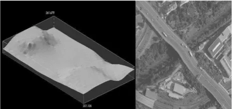
Figure 2. DMR 4G visualized as a shaded relief (left) and illustration of aerial photograph orthorectified via DMR 4G
before replenishment by models of bridges (right)
6. PROPOSAL OF DMR 4G IMPROVEMENT
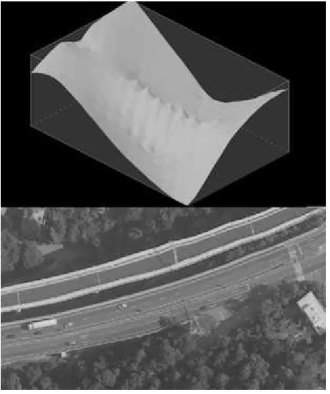
At first, conception based on a change of the altitude of current grid points was carried out. All modifications were processed by stereo plotting. The operator checked the model in the form of technical contour lines and the changes in altitude of model points while software automatically set a cursor on nodes of the grid. The handicap of the method lies on the fact that the edges of every object can´t be captured exactly. During the ortogonalization, altitude was interpolated from adjacent points. So, if the edge of objects like bridges occurred out of the points of grid, due to substantial vertical distances of the grid neighbouring points, the deformations of the image were found (Fig 3.). Instead of the changing of altitudes of grid nodes, by the 3D lines and 3D polygons we can exactly define the edges of all objects, especially the man-made ones. Simply inserting vector objects affects the DTM only at the vicinity of its perimeter. Therefore, additional information about object space delimitation and the removal of the DTM points situated inside of the ground plan of the object is required. This task may be easily and automatically achievable in the case of polygons. However, 3D lines have to be arranged manually or converted to polygons. Furthermore, we have to assure sharp changes of altitude on the edge of the object ground plan. Otherwise, a gentle change of the altitude can cause the deformation of orthorectified images in the outer neighbourhood of the object. It is often handled by the creation of the new vector element that is close fitting to the original vector object. Instead of the implemented object, the new element holds the altitude of DTM.
Figure 3. DMR 4G replenished by changing altitudes of model points (up) and its impact to the orthorectified aerial photograph
(down)
Actually, only 2 sources embrace the suitable object of interest covering the whole Czech Republic. The first one is the military Digital landscape model 1: 25 000 managed by the Geographical and Hydrometeorological Office, which incorporates the bridges and similar objects in the form of 3D lines of their lateral edges at that part of area and in the grid in the rest of the territory. The second source is the Fundamental Base of Geographic Data of the Czech Republic (ZABAGED®) - altimetry, which has been preferred due to a more appropriate form for the set purposes. Since 2005, original ZABAGED® - altimetry has been improved by 3D polygons of bridges, body of dams etc. via stereo plotting of aerial photographs acquired within the periodical aerial photography of the Czech Republic. Before the modelling, some topological errors of the ZABAGED® - altimetry had to be fixed. About 10 000 polygons were not enclosed (probably because of the incorrect use of the snap function). The problem has been solved by the automatic process in ArcGIS software via Feature to Polygon function. All line features that have end vertexes of a distance of less than 1 meter have been enclosed. After this alternation, only 50 features had to be edited manually. Further, all grade-separated intersections (only approximately 10 events for whole territory) had to be prepared to the fit form. The Czech Office for Surveying, Mapping and Cadastre workplaces use Inpho OrthoMaster for the ortogonalization of aerial photographs. The software allows processing of all commonly used DTM formats. Before orthogonalization, it converts several formats to its binary native format DTM. In processing vast datasets, it can be long-standing (one 40 x 50 km block lasts about 1 hour), therefore DTM as input format is prioritized Inpho DTM Toolkit has been used for the combination raster and vector datasets for DTM files. The output model was created by the Surface Modelling function. Enclosed polygons were placed in the Object shapes class and grid points to the Mass Points class. The polygons delimiting the top of objects were vertically projected to the original terrain by definition of the boundary for removing terrain points inside. Afterwards, an interpolation algorithm computed the altitude of the boundary from the terrain (fig 4.).
Figure 4. DMR 4G replenished by a bridge from ZABAGED® - altimetry (left) and aerial photograph orthorectified by this model (right)
Figure 6. Deformations or spatial discrepancies on orthogonalized photographs. Inaccurate object position (left),
inaccurate object altitude (midst) and dissension object with DTM (right)
For DMR 4G replenishment, the same procedure for the true orthophoto creation has been used. It encompasses some particularities. Disguised regions without image information in the orthogonalized photographs occur due to the central projection and the sharpness of elevation changes of the DSM. The regions are filled up by images from the other photographs which cover the same area. Therefore, large photograph overlaps (up to 90% for the forward and 80% to the side overlap) are advised. As the imaging with those parameters are markedly high-priced, it is usually carried out only in built-up areas. The project of the periodical aerial photography of the Czech Republic plan the 25% side overlap and the 60% forward overlap. Probably 10% of objects therefore are without image information from any photograph. In general, it is a matter of small spaces, which can be easily retouched.
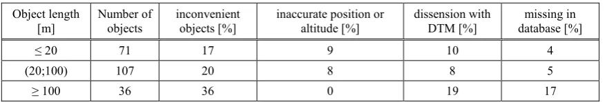
7. EXPERIMENTAL RESULTS
Large numbers of aerial images have been orthorectified for the verification of the proposed method and data source. Experimental sets contained 214 objects of interest. As a convenience, we only evaluated objects that didn't surpass deformations or spatial discrepancies larger than 2 pixels (0.5 m in object space). The analysis confirmed that 80% of the objects fulfilled conditions for immediate replenishment to DMR 4G by
the proposed method (Tab. 6). Another 20% of the objects should be acquired or rectified by stereo plotting. The most frequent deficiency was the inaccurate position or altitude of an object (Fig 6.), dissension object and DTM (it means that vector object was not vectored to the crossing with DTM). Some objects have not been in the database yet (actualization are carried out in 3-year periods). The results are captured in the Table 1.
8. CONCLUSION
Aerial photography, large format digital cameras, and the use of DMR 4G data generated from the airborne laser scanning certainly contribute to further increase the absolute accuracy of the Orthophoto of the CR. Absolute positional accuracy error of this product, depending on location, reaches around 20 cm. This value represents a practical limit of the absolute positional accuracy orthophoto. Merely a further increase in resolution, i.e. reducing the pixel size does not lead, without costly measures, to an improvement in the absolute position accuracy of orthophoto, but only improves the interpretability details. The Land Survey Office currently doesn’t plans to transition to a true orthophoto; for the future, the main objective is the achieved quality keeping of the Orthophoto of the CR. This requires:
more accurate values exterior orientation elements, measured during the photo-flight and proven by calibrated devices GNSS and IMU; free of systematic errors,
optimal use of artificially signalised control points for calculating AAT
local update the digital terrain model used for orthogonalization, possibly using digital elevation model 5th generation (after 2015).
The proposed method of DMR 4G replenishment has been presently applied at the Czech Land Survey Office and at the Military Geographical and Hydrometeorological Office during the production of the Ortophoto of the Czech Republic. Specifically, all aerial photographs covering the zones West and Centre have been orthogonalized by a hybrid DTM, which was created by the replenishment of DMR 4G by objects from ZABAGED® - altimetry. The model from zone East has been improved immediately since its completion in the year 2014. The frequency of deformations and spatial discrepancies obtained by the analysis of experimental samples has been confirmed during the processing. All faults are located during the checking up of the orthogonalized photographs. Inconvenient objects are then rectified by stereo plotting from current photographs. The method doesn´t cause any problems (except complications with insufficient overlaps) if the correct dataset is handled.
ACKNOWLEDGEMENT
Data was provided by Czech Land Survey Office.
REFERENCES
Amhar, F., Jansa, J., Ries. C., 1998. The Generation of the True-Orthophotos Using a 3D Building Model in Conjunction with a Conventional DTM. The Int. Archive of Phot. and R.S. Vol. 32, Part 4, Stuttgart, Germany, pp. 16-22.
Belka,L. et al., 2012. Technicka Zprava K Digitalnimu Modelu Reliefu 4 Generace DMR 4G, Technical Report, Czech Land Survey Office, Pardubice, Czech Republic, pp.1-11
Faltynova, M., Pavelka, K., Novy, P. , 2013. Mapping and visualisation of a part of medieval road - Via Magna, 13th International Multidisciplinary Scientific Geoconference and EXPO, SGEM 2013, Volume 2, Albena, Bulgaria, pp. 633-638
Pavelka, K., ezníček, J. , Faltýnová, M., 2014. Using of Airborne laser scanning for historical mining documentation. In 14th International Multidisciplinary Scientific Geoconference SGEM 2014 - Informatics, Geoinformatics and Remote Sensing - Conference Proceedings Volume II - Geodesy & Mine Surveying. Sofia: STEF92 Technology Ltd., vol. 2, p. 653-660. ISSN 1314-2704. ISBN 978-619-7105-11-7.
Rau, J.Y., Chen, N.Y., 2002. True Orthophoto Generation of Built-Up Areas Using Multi-View Images, PE&RS, Vol. 68, No6, USA, pp. 581-588.
Schickler, W., 1998. Operational Procedure for Automatic True Orthophoto Generation, The Int. Archive of Phot. and R.S., Vol. 32, Part 4, Stuttgart, Germany, pp. 527–532.
Švec, Z. , Matoušková, E., Pavelka, K., 2014. Improvement of the digital terrain model of the Czech Republic of the 4th generation for the aerial photographs orthorectification. 14th International Multidisciplinary Scientific Geoconference SGEM Object length
Table 6. Results of analysis for verifying suitability of ZABAGED® - altimetry as a data source for DMR 4G replenishment
2014, Conference Proceedings vol. III. Sofia: STEF92 Technology Ltd., art. no. 24, p. 191-198. ISSN 1314-2704. ISBN 978-619-7105-12-4
Švec, Z., Faltýnová, M. Pavelka, K. 2014. Digital aerotriangulation with vertical datum scale modification respects national horizontal coordinate system. 14th International Multidisciplinary Scientific Geoconference SGEM 2014, Conference Proceedings vol. III. Sofia: STEF92 Technology Ltd., art. no. 19, p. 153-160. ISSN 1314-2704. ISBN 978-619-7105-12-4.