GENERATION OF HIGH RESOLUTION AND HIGH PRECISION
ORTHORECTIFIED ROAD IMAGERY FROM MOBILE MAPPING SYSTEM
M. Sakamoto*, K. Tachibana, H. Shimamura
PASCO CORPORATION, 2-8-11 Higashiyama, Meguro-ku, Tokyo, 153-0043, Japan - (moittu9191, kainka9209,
hairdu9189)@pasco.co.jp
Commission V, ICWG V/I
KEY WORDS: Orthoimage, Mobile, Mapping, Colour, Adjustment, Laser scanning, Point Cloud, Close Range
ABSTRACT:
In this paper, a novel technique to generate a high resolution and high precision Orthorectified Road Imagery (ORI) by using spatial information acquired from a Mobile Mapping System (MMS) is introduced. The MMS was equipped with multiple sensors such as GPS, IMU, odometer, 2-6 digital cameras and 2-4 laser scanners. In this study, a Triangulated Irregular Network (TIN) based approach, similar to general aerial photogrammetry, was adopted to build a terrain model in order to generate ORI with high resolution and high geometric precision. Compared to aerial photogrammetry, there are several issues that are needed to be addressed. ORI is generated by merging multiple time sequence images of a short section. Hence, the influence of occlusion due to stationary objects, such as telephone poles, trees, footbridges, or moving objects, such as vehicles, pedestrians are very significant. Moreover, influences of light falloff at the edges of cameras, tone adjustment among images captured from different cameras or a round trip data acquisition of the same path, and time lag between image exposure and laser point acquisition also need to be addressed properly. The proposed method was applied to generate ORI with 1 cm resolution, from the actual MMS data sets. The ORI generated by the proposed technique was more clear, occlusion free and with higher resolution compared to the conventional orthorectified coloured point cloud imagery. Moreover, the visual interpretation of road features from the ORI was much easier. In addition, the experimental results also validated the effectiveness of proposed radiometric corrections. In occluded regions, the ORI was compensated by using other images captured from different angles. The validity of the image masking process, in the occluded regions, was also ascertained.
* Corresponding author.
1. INTRODUCTION
In recent years, a technology to gather high-density geographic spatial information by using Mobile Mapping System (MMS) has attracted attention and is in practical use (Manandhar et al., 2001, Ishikawa et al., 2006). MMS is a multiple sensor system equipped in vehicles by combining positioning sensors such as GPS/IMU and an odometer, digital still cameras, videos, and laser scanners for spatial data collection. In road infrastructure management, MMS has been practically used and its applicability in public survey of a large scale mapping has also been verified (Kim et al., 2006, Imanishi et al., 2011).
The spatial information acquired by MMS is in the form of digital images with Exterior Orientation Parameters (EOP) and three-dimensional point cloud that reflects the shape of geographical features. Conventionally, the Orthorectified Road Imagery (ORI) is generated by using either of the following two techniques. In the first technique, ORI is generated by assigning the colour information obtained from the still camera images or video camera images to the georeferenced point cloud obtained by laser scanning of the same region. However, the low spatial resolution is the main drawback of the ORI generated by this technique. In the second technique, ORI is generated by projecting and merging the imagery through projective transformation or affine transformation by assuming a short section of the road as a plane (Visintini, 2007). The ORI
generated from this technique suffers from an inferior geometric precision and/or an inclined ground objects (features) as a result of the inaccurate terrain modelling. Hence, in this study, a Triangulated Irregular Network (TIN) based approach, similar to general aerial photogrammetry, was adopted to build a terrain model in order to generate ORI with high resolution and high geometric precision. Compared to the general aerial photogrammetry, there are several issues which are needed to be addressed when generating ORI from MMS. For example, ORI is generated by merging multiple time sequence images of a short section. Therefore, the influence of occlusion due to stationary objects, such as telephone poles, trees, footbridges, or moving objects, such as vehicles, pedestrians are very significant. Moreover, influences of light falloff at the edges of cameras, tone adjustment among images captured from different cameras or a round trip data acquisition of the same path, and time lag between image exposure and laser scanned point acquisition also need to be addressed properly.
The ORI generated by the proposed technique is more clear, occlusion free and with higher resolution. Therefore, it can be utilized not only as a background image for digital mapping but also for inspection of road conditions like crack detection, management of road facilities such as manholes, digitizing or automatic extraction of road edges, sidewalk, pavement-marking and so on.
2. CONFIGURATION OF MMS AND USED DATASET
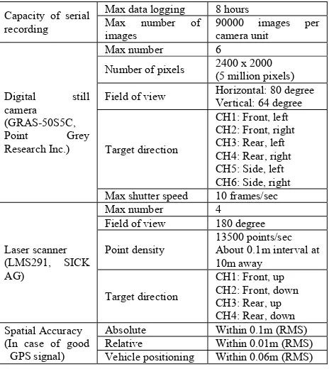
To generate the ORI, spatial data acquired from the “MMS-S220” and “MMS-X640” which were developed by Mitsubishi Electric Corp., were used in this study. These MMSs were equipped with multiple sensors such as GPS/IMU, odometer, 2-6 digital cameras and 2-4 laser scanners. The appearance and main specifications of “MMS-X640” are shown in Figure 1 and Table 1, respectively. In the generation of ORI, following spatial information acquired by MMS is utilized.
- Trajectory information of vehicle (time series position and attitude in world coordinate system)
- Interior orientation parameters of cameras
- Geometric alignment of cameras (position and attitude in coordinate system of GPS/IMU)
- Images captured by digital still cameras
- Three-dimensional laser point cloud acquired by laser scanners
Figure 1. System configuration of MMS
Capacity of serial recording
Max data logging 8 hours Max number of images
90000 images per camera unit
Number of pixels 2400 x 2000 (5 million pixels)
Field of view Horizontal: 80 degree Vertical: 64 degree
Target direction
CH1: Front, left CH2: Front, right CH3: Rear, left CH4: Rear, right CH5: Side, left CH6: Side, right Max shutter speed 10 frames/sec
Laser scanner About 0.1m interval at 10m away
Target direction
CH1: Front, up CH2: Front, down CH3: Rear, up Relative Within 0.01m (RMS)
Vehicle positioning Within 0.06m (RMS)
Table 1. Main specification of “MMS-X640”
3. METHODOLOGY OF ORI GENERATION
3.1 Process Flow
The process flow of ORI generation is shown in Figure 2. Details of processing are described as below.
Figure 2. Process flow of ORI generation
3.2 Filtering of Laser Scanned Point Cloud
When generating ORI, at first the laser points which do not represent the road surface is necessary to remove. For example, the point cloud which represents stationary structures, such as telephone poles, electric wires, signals, road information boards, guardrails and footbridges, or moving objects such as vehicles or pedestrians are removed. Moreover, the data acquisition timing between camera image and laser point cloud is not synchronized. Therefore, exact correspondence of camera images and shape of ground features, especially moving objects, cannot be obtained. Also, for the stationary objects which are unrelated to road surface, it is difficult to reproduce the shape exactly only from laser point cloud. In order to solve these problems, filtering of laser scanned point cloud and image masking process as described below are applied.
Under the premise that the MMS vehicle passes only through a road region, a short section of road surface plane is estimated by using point cloud in the trajectory area (defined as St) of MMS vehicles. With the point pi(xi, yi, zi), i=1,
L
,N (N is the number of point cloud which satisfies eq. (1)) in the area St, road surface plane is calculated with least-squares method by eq. (2).{
}
Filtering of laser scannedpoint cloud
Radiometric correction of input images
Approximation of road surface by TIN generation
Merge process of ORIs Image masking
Generation of time series intra-camera ORI
As the first-step, point cloud with the vertical interval which exceeds a given threshold is removed, where a threshold value is approximately set to the level difference of a road and a sidewalk. This process is applied for each point in the larger area of St, and will roughly retain only those laser scanned points which form a road surface and a sidewalk. Furthermore, in the second-step, for each pi, the point pm which satisfies eq. (3) is removed.
{
}
(
)
{
p num p p n p z z dh Nt}
pm= k∈ ( i), k− i < < (3)
where n(pi) = function which retrieves points neighbouring pi dh = threshold of vertical interval from zi
Nt = number of point which regards as isolated point
This process is for removing spike-like isolated points such as vehicles, telephone pole, trees which remain in the bottom area. Figure 3 shows an example of above process. Point cloud which reflects electric wire was removed properly.
Figure 3. Example of point cloud filtering
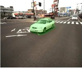
3.3 Image Masking
In the images acquired from MMS, generally area of road surface is concealed by various ground objects. In addition, there might be a chance where the MMS vehicle itself is reflected in the images depending on the camera mounting direction. Hence, it is necessary to remove the influence of these occluding features in order to generate a precise ORI. In case of aerial photogrammetry, it is possible to presume an occluded area and generate a precise orthorectified images by using feature modelling. Most of the ground objects are regarded as perpendicular structure, therefore modelling process is relatively easy in case of aerial photogrammetry. However, observation from the side view is main in MMS. Hence, modelling process of occluding features is difficult in many cases.
From the other point of view, the essential meaning of modelling of features is for specifying occluded area accurately but not for reconstruction of terrain model in ORI generation. Hence, preliminary image masking toward unrelated region of road surface where orthorectification process is not applied has an equivalent effect of exact ground object modelling. In this study, image masking was performed manually as shown in Figure 4.
3.4 Radiometric Correction of Input Images
Since ORI is generated by merging a lot of images, it is very important to apply radiometric correction of input images in order to improve the image quality or visual unification of output product. In this study, a brightness correction for light falloff at the edges and a newly introduced technique called “grey balance correction” are applied.
Figure 4. Example of image masking (coloured area by green)
3.4.1 Brightness correction for light falloff at the edges
In photography the influence of light falloff at edges due to the optical system of a wide-angle lens appears notably. Hence, an assumption that digital value of a pixel in camera image is given by linear relation to incidence energy, and peripheral brightness is compensated by eq. (4).
(
)
{
x y f}
y x V y x
V'( , )= ( , ) cosn tan−1 2+ 2 (4)
where V(x, y) = digital value of pixel in camera coordinates
V’(x, y) = digital value of pixel after compensation
f = focal length of camera lens
n = intensity parameter of compensation
In eq. (4) parameter n is needed to be adjusted in the range of 1.8-4.5 actually. The result of applying eq. (4) to actual images of MMS, is shown in Figure 5.
Figure 5. Effectiveness of peripheral brightness correction
3.4.2 Grey Balance Correction
In the synchronized photography with two or more cameras equipped in MMS, unnatural colour balance among camera is frequently observed as a result of individual specificity of colour sensitivity among cameras. Although the colour balance was adjusted before photography, or white balance compensation was applied even after data acquisition,
(a) Original MMS image (b) Processed result (a) ORI before filtering (b) ORI after filtering
sufficiently spectrally balanced result was not obtained for actual images. Here, we introduce a simplified radiometric calibration technique as a post-processing for previously captured images. This technique is based on the fact that, spectrally, most of the road surface is close to grey. The basic procedure is detecting the road surface area to adjust the colour balance of these areas. The process is explained as follows.
(Step 1) Under the hypothesis that a trajectory of MMS vehicle corresponds to a road, the passed area of vehicle is roughly projected onto the image with trajectory information. A projected area is defined as area Sv.
(Step 2) From area Sv, image pixels are sampled except for the case that pixel brightness is near saturation due to a white line or influence of a smear, too dark pixels, or pixels in which the colour balance of RGB is significantly different from grey.
(Step 3) From the area outside of Sv, pixels with similar colour as pixels sampled in Step 2 are also sampled.
(Step 4) The brightness balance among RGB component is adjusted so that sampled pixels corresponds closer to grey. At this moment, the images in which the adjusted value does not exceed a given value are ignored.
(Step 5) Continuous processing till Step 4 is applied to all camera images. In order to stabilize the process, the amount of compensation for a target image is computed by referring to the time series images before and after the target image. An example of result obtained by the proposed grey balance correction is shown in Figure 6. It is confirmed that the proposed method realizes more natural colour balance.
Figure 6. Application result of grey balance correction
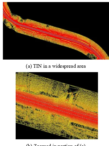
3.5 Approximation of Road Surface by TIN
The topography of road surface is approximated by TIN which is generated by applying two-dimensional constrained Delaunay triangulation (Sloan, 1993) to filtered laser scanned point cloud described in section 3.2 and/or digitized breaklines such as road edges. By using above terrain model and masked area information described in section 3.3, ORI is generated more faithfully with high geometric precision. Figure 7 shows an example of TIN generated from laser scanned point cloud acquired from MMS. The point cloud and trajectory of a vehicle are coloured by red and cyan respectively.
3.6 Generation of Time Series Intra-camera ORI
EOP of each camera at each acquiring time is calculated from the GPS/IMU and the geometry of the camera mounting. For the MMS that we employed, position and attitude data of a vehicle is recorded in ENU (East, North, Up) coordinate system. Hence, EOP in the plane rectangular coordinate system for each camera is calculated by the serial procedure illustrated in Figure
8. Coordinate transformation between world coordinate system and image coordinate system for digital terrain modelling of road surface is performed based on interior orientation parameters and EOP of each camera. Compensation of lens distortion is also taken into consideration at this stage.
For each camera, orthorectification with specified ground resolution is carried out by projective transformation per triangles of TIN in time series camera images. In this process, peripheral brightness correction and/or grey balance correction for each image is applied as a radiometric correction, and generated ORIs are merged in each camera individually. ORI generated by this procedure is called intra-camera ORI.
Figure 7. Example of TIN generation result for MMS data
Figure 8. Procedure to calculate EOP of each camera
3.7 Merge process of ORIs
As the final process, ORIs generated from time series intra-cameras and/or different strips (in case of round trip) are merged together considering geometric realignment and colour tone adjustment.
Transformation to geocentric coordinate system
Geoid height compensation of EOP
Transformation to latitude longitude coordinate system
Meridian convergence angle compensation of EOP
Transformation with geometry of each camera
i EOP of vehicle in ENU
coordinate system
EOP of each camera in plane rectangular coordinate Transformation to plane
rectangular coordinate system
(a) Original MMS image (b) Processed result
(a) TIN in a widespread area
(b) Zoomed in portion of (a)
3.7.1 Geometric realignment of ORIs
As shown in Table 1, since the relative positioning accuracy of MMS is comparatively high and stable, the ORIs generated in a same strip (including intra-camera ORI) have geometrically high precision. On the other hand, it is often observed that ORIs generated from different strips may suffer from distinct position gap which is equivalent to the specification value of absolute MMS vehicle positioning accuracy. In order to solve this problem, ORIs from different strips are translated horizontally with common tie points which are provided manually and with ground control points if possible.
3.7.2 Colour Tone Adjustment for ORIs
When colour tone adjustment is applied to time series images captured from the same camera, ideal adjustment is realized between two sequential images. However, if this process was applied to images of whole photography strip, it is ascertained that colour balance of images at the head and end of a strip was remarkably different. On the contrary, even if above processing was not applied, there was almost no influence on image quality provided that the severe influence of lighting environment brought by low solar altitude did not occur. Thus, in the generation of intra-camera ORI, only radiometric compensation mentioned above is sufficient.
However, intra-camera ORIs generated from different cameras (inter-cameras) or strips have considerable difference in colour tone caused by individual specificity of colour sensitivity among cameras and/or lighting environment. Figure 9 shows the colour tone difference among the images obtained by six cameras equipped in “MMS-X640” projected in spherical coordinate system. To deal with above problem, colour tone of ORIs from inter-camera or strips is adjusted by the statistical conversion defined in eq. (5).
{
v w v w dv}
from corresponding position of different ORIswi' = brightness of pixel colour component after conversion dv = threshold value for pixel sampling
Pixel sampling for colour tone adjustment is performed from overlapping area in ORIs by ignoring pixels such as saturated pixel, too dark pixel, and pixel in which the brightness of colour component is significantly different.
Figure 9. Colour tone difference among MMS cameras
4. APPLICATION RESULT
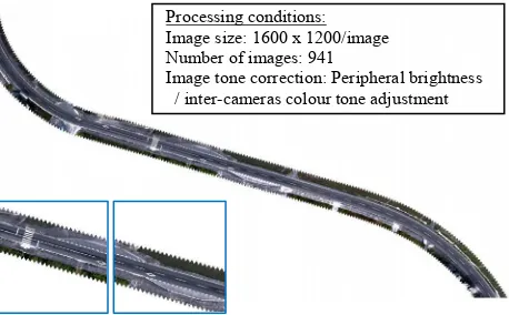
The proposed method was applied to generate ORIs at varying conditions for comparison with the conventional MMS data sets. A typical processed result is shown in Figure 10 which was obtained by merging 941 images taken during a round trip.
Figure 10. Example of typical ORI from “MMS-S220”
Figure 11 shows the comparison of conventional orthorectified coloured point cloud imagery and ORI obtained by the proposed technique with 1cm ground resolution. The ORI generated from the proposed technique is more clear, occlusion free and with higher resolution. Influences of occlusion due to telephone poles, trees and shadow of vehicles have been adequately removed by compensating with other images.
Figure 11. Comparison of ORI
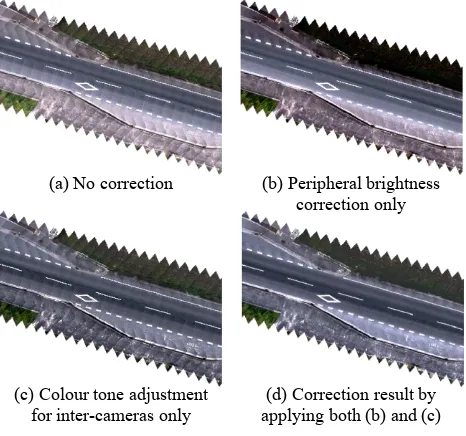
The effect of peripheral brightness correction and colour tone adjustment for inter-camera ORIs are shown in Figure 12. It is ascertained that the boundary between intra-camera ORIs becomes difficult to distinguish due to peripheral brightness correction. Moreover, colour tone adjustment for inter-camera ORIs is useful in the visual unification of image tone.
Figure 13 shows a section of ORI with 1cm ground resolution. Since the ORI generated by the proposed technique is of a superior quality, white lines, cracks, a manhole and a grating cover can be distinguished clearly. Because it is much easier to perform visual interpretation of road surface objects by the ORI, it can be also utilized for effective inspection or maintenance of road pavement, such as cracks, stripping, rutting, and so on.
Figure 14 shows the experimental results to confirm the effectiveness of image masking and image filling. From Figure 14(a) and Figure 14(b), the validity of masking process of the ground objects unrelated to road surface is ascertained. Here, the area of mobile vehicle, telegraph poles and trees were
(a) Orthorectified coloured point cloud imagery
(b) ORI generated by proposed method
Processing conditions: Image size: 1600 x 1200/image Number of images: 941
Image tone correction: Peripheral brightness / inter-cameras colour tone adjustment
masked by the procedure described in section 3.3, and were compensated by other intra-camera ORIs. The lost areas of ORI shown in Figure 14(b) which was generated by rear cameras were appropriately filled by inter-camera ORIs with front cameras (see Figure 14(c)) as shown in Figure 14(d). Thus, by using two or more cameras directed towards various directions, it is possible to lessen the influence of occlusions in ORI generation.
Figure 12. Comparison of applying radiometric correction and/or colour tone adjustment
Figure 13. Enlarged image of 1cm ground resolution ORI
5. CONCLUSIONS
In this paper, an ORI generation technique for MMS was discussed and applied to actual dataset of MMS. As a result, the ORI generated by the proposed approach was more clear, occlusion free and with both higher resolution and high geometric precision compared to the conventional ORI, such as orthorectified coloured point cloud imagery. In the newly generated ORI, the visual interpretation of road features was much easier. Therefore, it can be also utilized for effective inspection or maintenance of road pavement.
In the proposed approach, most of the processing is executed automatically; however, image masking process was still performed by manual operation. This task is very laborious
because the images captured by MMS amounts to significant number. Hence, it is necessary to develop some automatic or semiautomatic image masking technique for more efficent ORI generation. In addition, in order to realize higher geometric precision both in intra-ORI and inter-ORI, re-estimation of vehicle trajectory (position and attitude) with a technique such as bundle adjustment is needed. Filtering of point cloud involving modification of position (smoothing) is also necessary for approximating more ideal terrain model of road surface.
Figure 14. Effectiveness of image masking and filling
REFERENCES
Imanishi, A., Tachibana K., Tsukahara, K., 2011. The Development of Accuracy Maintenance Method for Mobile Mapping System (MMS) Data at GPS Invisible Area, FIG Working Week 2011, Bridging the Gap between Cultures, Marrakech, Morocco.
Ishikawa, K., Takiguchi, J., Hashizume, T., Amano, Y., 2006. A Mobile Mapping System for road data capture based on 3D road model, IEEE International Conference on Control Applications, Munich, Germany, pp.638-643.
Kim, G., Sohn, H., Song, Y., 2006. Road Infrastructure Data Acquisition Using a Vehicle-Based Mobile Mapping System,
Computer-Aided Civil and Infrastructure Engineering, Vol. 21,
pp. 346-356.
Manandhar, D., Shibasaki, R., 2001. VEHICLE-BORNE LASER MAPPING SYSTEM (VLMS) FOR 3-D GIS, Geoscience and Remote Sensing Symposium, IGARSS '01, IEEE 2001 International, pp. 2073-2075.
Sloan, S. W., 1993. A Fast Algorithm for Generating Constrained Delaunay Triangulations, Computers and Structures, Vol. 47, No. 3, pp. 441-450.
Visintini, D., 2007. ROAD SURVEY BY KALMAN FILTER RECTIFICATION OF IMAGE SEQUENCES ACQUIRED WITH A MONOSCOPIC LOW-COST MMS, The 5th International Symposium on Mobile Mapping Technology, Padua, Italy, ISPRS Archives, Vol. XXXVI-5/C55.
(a) Pedestrian crossing (b) Manhole, grating cover, and roadway cracks (a) No correction (b) Peripheral brightness
correction only
(c) Colour tone adjustment for inter-cameras only
(d) Correction result by applying both (b) and (c)
(a) ORI by rear camera without image masking
(b) ORI by rear camera with image masking
(c) ORI by front camera without image masking
(d) Filled ORI of the result (b) with (c)