Open Geospatial Consortium, Inc.
OpenGIS
®
Implementation Specification:
Coordinate Transformation Services
Revision 1.00
OpenGIS Project Document 01-009
Release Date: 12 January 2001
Copyright © Open Geospatial Consortium, Inc. (2005)
License Agreement
Permission is hereby granted by the Open Geospatial Consortium, ("Licensor"), free of charge and subject to the terms set forth below, to any person obtaining a copy of this Intellectual Property and any associated documentation, to deal in the Intellectual Property without restriction (except as set forth below), including without limitation the rights to implement, use, copy, modify, merge, publish, distribute, and/or sublicense copies of the Intellectual Property, and to permit persons to whom the Intellectual Property is furnished to do so, provided that all copyright notices on the intellectual property are retained intact and that each person to whom the Intellectual Property is furnished agrees to the terms of this Agreement.
If you modify the Intellectual Property, all copies of the modified Intellectual Property must include, in addition to the above copyright notice, a notice that the Intellectual Property includes modifications that have not been approved or adopted by LICENSOR.
THIS LICENSE IS A COPYRIGHT LICENSE ONLY, AND DOES NOT CONVEY ANY RIGHTS UNDER ANY PATENTS THAT MAY BE IN FORCE ANYWHERE IN THE WORLD.
THE INTELLECTUAL PROPERTY IS PROVIDED "AS IS", WITHOUT WARRANTY OF ANY KIND, EXPRESS OR IMPLIED, INCLUDING BUT NOT LIMITED TO THE WARRANTIES OF MERCHANTABILITY, FITNESS FOR A PARTICULAR PURPOSE, AND NONINFRINGEMENT OF THIRD PARTY RIGHTS. THE COPYRIGHT HOLDER OR HOLDERS INCLUDED IN THIS NOTICE DO NOT WARRANT THAT THE FUNCTIONS CONTAINED IN THE INTELLECTUAL PROPERTY WILL MEET YOUR REQUIREMENTS OR THAT THE OPERATION OF THE INTELLECTUAL PROPERTY WILL BE UNINTERRUPTED OR ERROR FREE. ANY USE OF THE INTELLECTUAL PROPERTY SHALL BE MADE ENTIRELY AT THE USER’S OWN RISK. IN NO EVENT SHALL THE COPYRIGHT HOLDER OR ANY CONTRIBUTOR OF INTELLECTUAL PROPERTY RIGHTS TO THE INTELLECTUAL PROPERTY BE LIABLE FOR ANY CLAIM, OR ANY DIRECT, SPECIAL, INDIRECT OR CONSEQUENTIAL DAMAGES, OR ANY DAMAGES WHATSOEVER RESULTING FROM ANY ALLEGED INFRINGEMENT OR ANY LOSS OF USE, DATA OR PROFITS, WHETHER IN AN ACTION OF CONTRACT, NEGLIGENCE OR UNDER ANY OTHER LEGAL THEORY, ARISING OUT OF OR IN CONNECTION WITH THE IMPLEMENTATION, USE, COMMERCIALIZATION OR PERFORMANCE OF THIS INTELLECTUAL PROPERTY.
This license is effective until terminated. You may terminate it at any time by destroying the Intellectual Property together with all copies in any form. The license will also terminate if you fail to comply with any term or condition of this Agreement. Except as provided in the following sentence, no such termination of this license shall require the termination of any third party end-user sublicense to the Intellectual Property which is in force as of the date of notice of such termination. In addition, should the Intellectual Property, or the operation of the Intellectual Property, infringe, or in LICENSOR’s sole opinion be likely to infringe, any patent, copyright, trademark or other right of a third party, you agree that LICENSOR, in its sole discretion, may terminate this license without any compensation or liability to you, your licensees or any other party. You agree upon termination of any kind to destroy or cause to be destroyed the Intellectual Property together with all copies in any form, whether held by you or by any third party.
Except as contained in this notice, the name of LICENSOR or of any other holder of a copyright in all or part of the Intellectual Property shall not be used in advertising or otherwise to promote the sale, use or other dealings in this Intellectual Property without prior written authorization of LICENSOR or such copyright holder. LICENSOR is and shall at all times be the sole entity that may authorize you or any third party to use certification marks, trademarks or other special designations to indicate compliance with any LICENSOR standards or specifications.
This Agreement is governed by the laws of the Commonwealth of Massachusetts. The application to this Agreement of the United Nations Convention on Contracts for the International Sale of Goods is hereby expressly excluded. In the event any provision of this Agreement shall be deemed unenforceable, void or invalid, such provision shall be modified so as to make it valid and enforceable, and as so modified the entire Agreement shall remain in full force and effect. No decision, action or inaction by LICENSOR shall be construed to be a waiver of any rights or remedies available to it.
Table of Contents
1 Preface ...10
1.1 Submitting Companies ...10
1.2 Submission Contact Point ...10
1.3 Revision History ...10
3.6 Constraints on Operation Sequencing ...13
4 Coordinate System Identity ...14
5 Domains of Validity ...15
6 Profiles ...16
6.1 COM profile ...16
6.1.1 Generating COM Type Libraries ... 16
6.1.2 COM Categories ... 16
6.2 CORBA profile...17
6.3 Java profile ...17
7 Well-Known Text format...18
7.1 Math Transform WKT...18
7.2 Coordinate System WKT...18
7.3 Description of WKT keywords ...19
7.3.1 AUTHORITY ... 19
8 Relationship to Simple Features ...24
8.1 Compatibility of Well-Known Text ...24
8.2 Name changes from SF-SRS to CS ...24
8.3 Authority Codes...24
9 Processes...25
9.2 Create a NAD83 California Zone 1 CS ...25
9.3 Store and recall CS in a Database...25
9.4 Merge California Zone 1 data in NAD27 and NAD83 ...26
9.5 Transform steps from NAD27 to NAD83 in California Zone 1 ...27
10 Parameterized Transforms ...30
10.6.1 Cartographic Projection Transform Parameters ... 35
10.6.1.1 Transverse_Mercator Projection ...35
10.6.1.2 Lambert_Conformal_Conic_1SP...35
10.6.1.3 Lambert_Conformal_Conic_2SP...35
11 Referencing objects by ID versus Value...36
11.1 Registered WKT Authorities ...36
11.1.1 EPSG/POSC ... 36
12 UML Documentation ...38
12.1 Packages ...38
12.2 PT Logical Package: Positioning...39
12.2.1 PT_CoordinatePoint Class... 40
12.2.1.1 ord (Attribute) :...40
12.2.2 PT_Envelope Class ... 41
12.2.2.1 maxCP (Attribute) : ...41
12.2.2.2 minCP (Attribute) : ...41
12.2.3 PT_Matrix Class... 42
12.2.3.1 elt (Attribute) : ...42
12.3 CS Logical Package: Co-ordinate Systems ...43
12.3.1 CS_AngularUnit Class ... 48
12.3.1.1 radiansPerUnit (Attribute) : ...48
12.3.2 CS_AxisInfo Class ... 49
12.3.2.1 name (Attribute) : ...49
12.3.2.2 orientation (Attribute) : ...49
12.3.3 CS_AxisOrientationEnum Class ... 50
12.3.3.1 CS_AO_Other (Attribute) : 0...50
12.3.3.2 CS_AO_North (Attribute) : 1...50
12.3.3.3 CS_AO_South (Attribute) : 2 ...50
12.3.3.4 CS_AO_East (Attribute) : 3 ...50
12.3.3.5 CS_AO_West (Attribute) : 4 ...50
12.3.3.6 CS_AO_Up (Attribute) : 5 ...50
12.3.3.7 CS_AO_Down (Attribute) : 6 ...50
12.3.4 CS_CompoundCoordinateSystem Class... 51
12.3.4.1 headCS (Attribute) : ...51
12.3.4.2 tailCS (Attribute) : ...51
12.3.5 CS_CoordinateSystem Class ... 52
12.3.5.1 defaultEnvelope (Attribute) : ...52
12.3.5.2 dimension (Attribute) :...52
12.3.5.3 getAxis (dimension:Integer) : CS_AxisInfo ...52
12.3.5.4 getUnits (dimension:Integer) : CS_Unit ...52
12.3.6 CS_CoordinateSystemAuthorityFactory Class ... 53
12.3.6.1 authority (Attribute) : ...53
12.3.6.2 createAngularUnit (code:CharacterString) : CS_AngularUnit ...53
12.3.6.3 createCompoundCoordinateSystem (code:CharacterString) : CS_CompoundCoordinateSystem ...53
12.3.6.5 createGeographicCoordinateSystem (code:CharacterString) :
CS_GeographicCoordinateSystem ...53
12.3.6.6 createHorizontalCoordinateSystem (code:CharacterString) : CS_HorizontalCoordinateSystem ...53
12.3.6.7 createHorizontalDatum (code:CharacterString) : CS_HorizontalDatum ...53
12.3.6.8 createLinearUnit (code:CharacterString) : CS_LinearUnit ...53
12.3.6.9 createPrimeMeridian (code:CharacterString) : CS_PrimeMeridian ...53
12.3.6.10 createProjectedCoordinateSystem (code:CharacterString) : CS_ProjectedCoordinateSystem ...53
12.3.6.11 createVerticalCoordinateSystem (code:CharacterString) : CS_VerticalCoordinateSystem ...53
12.3.6.12 createVerticalDatum (code:CharacterString) : CS_VerticalDatum ...53
12.3.6.13 descriptionText (code:CharacterString) : CharacterString ...53
12.3.6.14 geoidFromWKTName (wkt:CharacterString) : CharacterString ...54
12.3.6.15 wktGeoidName (geoid:Integer) : CharacterString ...54
12.3.7 CS_CoordinateSystemFactory Class ... 55
12.3.7.1 createCompoundCoordinateSystem (name:CharacterString, head:CS_CoordinateSystem, tail:CS_CoordinateSystem) : CS_CompoundCoordinateSystem ...55
12.3.7.2 createEllipsoid (name:CharacterString, semiMajorAxis:Double, semiMinorAxis:Double, linearUnit:CS_LinearUnit) : CS_Ellipsoid ...55
12.3.7.3 createFittedCoordinateSystem (name:CharacterString, base:CS_CoordinateSystem, toBaseWKT:CharacterString, arAxes:Sequence<CS_AxisInfo>) : CS_FittedCoordinateSystem ...55
12.3.7.4 createFlattenedSphere (name:CharacterString, semiMajorAxis:Double, inverseFlattening:Double, linearUnit:CS_LinearUnit) : CS_Ellipsoid ...55
12.3.7.5 createFromWKT (wellKnownText:CharacterString) : CS_CoordinateSystem ..55
12.3.7.6 createFromXML (xml:CharacterString) : CS_CoordinateSystem...55
12.3.7.7 createGeographicCoordinateSystem (name:CharacterString, angularUnit:CS_AngularUnit, horizontalDatum:CS_HorizontalDatum, primeMeridian:CS_PrimeMeridian, axis0:CS_AxisInfo, axis1:CS_AxisInfo) : CS_GeographicCoordinateSystem ...56
12.3.7.8 createHorizontalDatum (name:CharacterString, horizontalDatumType:CS_DatumType, ellipsoid:CS_Ellipsoid, toWGS84:CS_WGS84ConversionInfo) : CS_HorizontalDatum ...56
12.3.7.9 createLocalCoordinateSystem (name:CharacterString, datum:CS_LocalDatum, unit:CS_Unit, arAxes:Sequence<CS_AxisInfo>) : CS_LocalCoordinateSystem ...56
12.3.7.10 createLocalDatum (name:CharacterString, localDatumType:CS_DatumType) : CS_LocalDatum...56
12.3.7.11 createPrimeMeridian (name:CharacterString, angularUnit:CS_AngularUnit, longitude:Double) : CS_PrimeMeridian ...56
12.3.7.12 createProjectedCoordinateSystem (name:CharacterString, gcs:CS_GeographicCoordinateSystem, projection:CS_Projection, linearUnit:CS_LinearUnit, axis0:CS_AxisInfo, axis1:CS_AxisInfo) : CS_ProjectedCoordinateSystem ...56
12.3.7.13 createProjection (name:CharacterString, wktProjectionClass:CharacterString, parameters:Sequence<CS_ProjectionParameter>) : CS_Projection...56
12.3.7.14 createVerticalCoordinateSystem (name:CharacterString, verticalDatum:CS_VerticalDatum, verticalUnit:CS_LinearUnit, axis:CS_AxisInfo) : CS_VerticalCoordinateSystem ...56
12.3.7.15 createVerticalDatum (name:CharacterString, verticalDatumType:CS_DatumType) : CS_VerticalDatum ...57
12.3.8 CS_Datum Class ... 58
12.3.8.1 datumType (Attribute) : ...58
12.3.9 CS_DatumType Class ... 59
12.3.9.2 CS_HD_Geocentric (Attribute) : 1002 ...59
12.3.9.3 CS_HD_Max (Attribute) : 1999...59
12.3.9.4 CS_HD_Min (Attribute) : 1000...59
12.3.9.5 CS_HD_Other (Attribute) : 1000...59
12.3.9.6 CS_LD_Max (Attribute) : 32767 ...59
12.3.9.7 CS_LD_Min (Attribute) : 10000 ...59
12.3.9.8 CS_VD_AltitudeBarometric (Attribute) : 2003 ...59
12.3.9.9 CS_VD_Depth (Attribute) : 2006 ...59
12.3.9.10 CS_VD_Ellipsoidal (Attribute) : 2002 ...59
12.3.9.11 CS_VD_GeoidModelDerived (Attribute) : 2005...60
12.3.9.12 CS_VD_Max (Attribute) : 2999...60
12.3.9.13 CS_VD_Min (Attribute) : 2000...60
12.3.9.14 CS_VD_Normal (Attribute) : 2004...60
12.3.9.15 CS_VD_Orthometric (Attribute) : 2001...60
12.3.9.16 CS_VD_Other (Attribute) : 2000 ...60
12.3.10 CS_Ellipsoid Class... 61
12.3.10.1 axisUnit (Attribute) :...61
12.3.10.2 inverseFlattening (Attribute) : ...61
12.3.10.3 ivfDefinitive (Attribute) : ...61
12.3.10.4 semiMajorAxis (Attribute) : ...61
12.3.10.5 semiMinorAxis (Attribute) : ...61
12.3.11 CS_FittedCoordinateSystem Class ... 62
12.3.11.1 baseCoordinateSystem (Attribute) : ...62
12.3.11.2 toBase (Attribute) : ...62
12.3.12 CS_GeocentricCoordinateSystem Class... 62
12.3.12.1 horizontalDatum (Attribute) : ...62
12.3.12.2 linearUnit (Attribute) : ...62
12.3.12.3 primeMeridian (Attribute) :...62
12.3.13 CS_GeographicCoordinateSystem Class... 63
12.3.13.1 angularUnit (Attribute) : ...63
12.3.13.2 numConversionToWGS84 (Attribute) : ...63
12.3.13.3 primeMeridian (Attribute) :...63
12.3.13.4 getWGS84ConversionInfo (index:Integer) : CS_WGS84ConversionInfo ...63
12.3.14 CS_HorizontalCoordinateSystem Class ... 64
12.3.14.1 horizontalDatum (Attribute) : ...64
12.3.15 CS_HorizontalDatum Class ... 65
12.3.15.1 ellipsoid (Attribute) :...65
12.3.15.2 WGS84Parameters (Attribute) : ...65
12.3.16 CS_Info Class ... 66
12.3.16.1 abbreviation (Attribute) : ...66
12.3.16.2 alias (Attribute) : ...66
12.3.16.3 authority (Attribute) :...66
12.3.16.4 authorityCode (Attribute) : ...66
12.3.16.5 name (Attribute) :...66
12.3.16.6 remarks (Attribute) :...66
12.3.16.7 WKT (Attribute) :...66
12.3.16.8 XML (Attribute) : ...67
12.3.17 CS_LinearUnit Class... 68
12.3.20.1 angularUnit (Attribute) : ...71
12.3.20.2 longitude (Attribute) : ...71
12.3.21.1 geographicCoordinateSystem (Attribute) : ...72
12.3.21.2 linearUnit (Attribute) : ...72
12.3.21.3 projection (Attribute) : ...72
12.3.22 CS_Projection Class ... 73
12.3.22.1 className (Attribute) :...73
12.3.22.2 numParameters (Attribute) : ...73
12.3.22.3 getParameter (index:Integer) : CS_ProjectionParameter ...73
12.3.23 CS_ProjectionParameter Class ... 74
12.3.23.1 name (Attribute) :...74
12.3.23.2 value (Attribute) : ...74
12.3.24 CS_Unit Class... 75
12.3.25 CS_VerticalCoordinateSystem Class ... 76
12.3.25.1 verticalDatum (Attribute) :...76
12.3.25.2 verticalUnit (Attribute) :...76
12.3.26 CS_VerticalDatum Class ... 77
12.3.27 CS_WGS84ConversionInfo Class ... 78
12.3.27.1 areaOfUse (Attribute) : ...78
12.3.27.2 dx (Attribute) : ...78
12.3.27.3 dy (Attribute) : ...78
12.3.27.4 dz (Attribute) : ...78
12.3.27.5 ex (Attribute) : ...78
12.3.27.6 ey (Attribute) : ...78
12.3.27.7 ez (Attribute) : ...78
12.3.27.8 ppm (Attribute) :...78
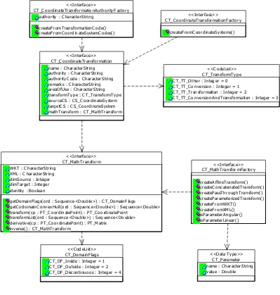
12.4 CT Logical Package: Co-ordinate Transformations ...79
12.4.1 CT_CoordinateTransformation Class ... 80
12.4.1.1 areaOfUse (Attribute) :...80
12.4.1.2 authority (Attribute) : ...80
12.4.1.3 authorityCode (Attribute) : ...80
12.4.1.4 mathTransform (Attribute) : ...80
12.4.1.5 name (Attribute) : ...80
12.4.1.6 remarks (Attribute) : ...80
12.4.1.7 sourceCS (Attribute) : ...80
12.4.1.8 targetCS (Attribute) :...80
12.4.1.9 transformType (Attribute) :...80
12.4.2 CT_CoordinateTransformationAuthorityFactory Class... 81
12.4.2.1 authority (Attribute) : ...81
12.4.2.2 createFromCoordinateSystemCodes (sourceCode:CharacterString, targetCode: CharacterString) : CT_CoordinateTransformation...81
12.4.2.3 createFromTransformationCode (code:CharacterString) : CT_CoordinateTransformation ...81
12.4.3 CT_CoordinateTransformationFactory Class ... 82
12.4.3.1 createFromCoordinateSystems (sourceCS:CS_CoordinateSystem, targetCS:CS_CoordinateSystem) : CT_CoordinateTransformation...82
12.4.4 CT_DomainFlags Class ... 83
12.4.4.1 CT_DF_Inside (Attribute) : 1...83
12.4.4.2 CT_DF_Outside (Attribute) : 2...83
12.4.4.3 CT_DF_Discontinuous (Attribute) : 4...83
12.4.5 CT_MathTransform Class... 84
12.4.5.1 dimSource (Attribute) :...84
12.4.5.2 dimTarget (Attribute) :...84
12.4.5.3 identity (Attribute) :...84
12.4.5.4 WKT (Attribute) : ...84
12.4.5.5 XML (Attribute) :...84
12.4.5.6 derivative (cp:PT_CoordinatePoint) : PT_Matrix ...84
12.4.5.8 getDomainFlags (ord:Sequence<Double>) : CT_DomainFlags...85
12.4.5.9 inverse () : CT_MathTransform ...85
12.4.5.10 transform (cp:PT_CoordinatePoint) : PT_CoordinatePoint...85
12.4.5.11 transformList (ord:Sequence<Double>) : Sequence<Double> ...85
12.4.6 CT_MathTransformFactory` Class ... 86
12.4.6.1 createAffineTransform (matrix:PT_Matrix) : CT_MathTransform ...86
12.4.6.2 createConcatenatedTransform (transform1:CT_MathTransform, transform2:CT_MathTransform) : CT_MathTransform...86
12.4.6.3 createFromWKT (wellKnownText:CharacterString) : CT_MathTransform...87
12.4.6.4 createFromXML (xml:CharacterString) : CT_MathTransform ...87
12.4.6.5 createParameterizedTransform (classification:CharacterString, parameters:Sequence<CT_Parameter>) : CT_MathTransform...87
12.4.6.6 createPassThroughTransform (firstAffectedOrdinate:Integer, subTransform:CT_MathTransform) : CT_MathTransform...87
12.4.6.7 isParameterAngular (parameterName:CharacterString) : Boolean...87
12.4.6.8 isParameterLinear (parameterName:CharacterString) : Boolean ...87
12.4.7 CT_Parameter Class ... 88
12.4.7.1 name (Attribute) : ...88
12.4.7.2 value (Attribute) : ...88
12.4.8 CT_TransformType Class... 89
12.4.8.1 CT_TT_Other (Attribute) : 0...89
12.4.8.2 CT_TT_Conversion (Attribute) : 1 ...89
12.4.8.3 CT_TT_Transformation (Attribute) : 2 ...89
12.4.8.4 CT_TT_ConversionAndTransformation (Attribute) : 3...89
13 Appendix A: Interface Definition Files...90
13.1 COM ...90
14 Appendix B: Guidelines for development of Conformance Test... 111
14.1 Ask vendors which profiles will be implemented ... 111
14.2 Ask TC members to list possible errors... 111
14.3 List core mandatory transforms and projections ... 111
14.4 List coordinate systems in WKT and XML... 111
14.5 Acquire reference implementation of projection code ... 112
14.6 Prepare list of known points in different coordinate systems ... 112
15 Appendix C: Informative ... 113
15.1 XML ... 113
15.1.1 XML Definition... 113
Table of Figures
Figure 1: Package interface dependencies ...12
Figure 2: Classifications of parameterized math transforms ...30
Figure 3: EPSG code ranges...36
Figure 4. Packages...38
Figure 5. Positioning (Class Diagram) ...39
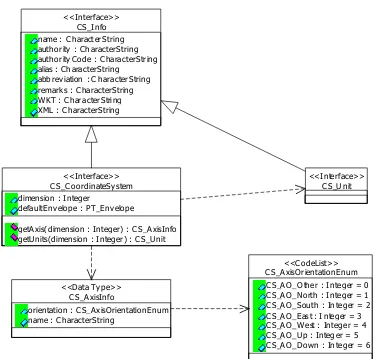
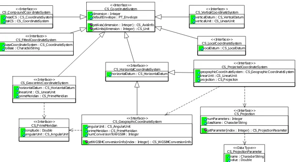
Figure 6. Coordinate System (Class Diagram) ...43
Figure 7. Coordinate System Classes (Class Diagram) ...44
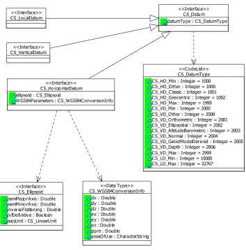
Figure 8. Datums (Class Diagram) ...45
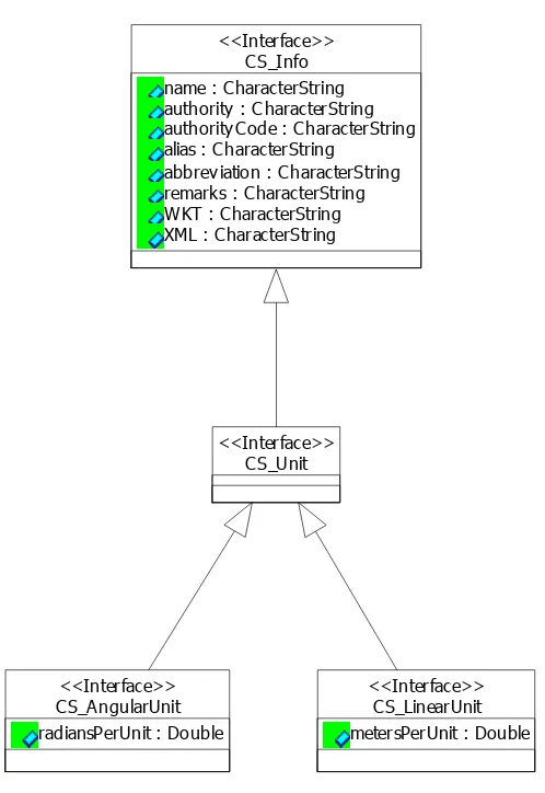
Figure 9. Units (Class Diagram)...46
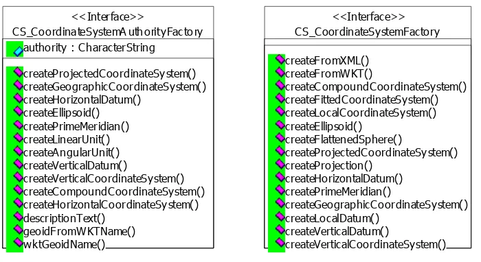
Figure 10. Coordinate System Factories (Class Diagram)...47
1 Preface
1.1 Submitting
Companies
The following company is pleased to submit this specification in response to the OGC Request 9, “A Request for Proposals: OpenGIS Coordinate Transformation Services” (OpenGIS Project Document Number 99-057):
Computer Aided Development Corporation (Cadcorp) Ltd.
1.2
Submission Contact Point
All questions about the submission should be directed to:
Martin Daly, Cadcorp Ltd, Sterling Court, Norton Road, Stevenage, Herts, UK SG1 2JY
E-mail: [email protected]
Thanks are due to Arliss Whiteside for his assistance in automatically generating much of this document from the accompanying UML model.
1.3 Revision
History
1.3.1 00-007r4
Substantial changes have been made to this document in the interests of clarity. The significant changes to the specification are as follows:
• The XML specified in 00-007r3 has been moved to an informative Appendix.
2 Overview
This Implementation Specification provides interfaces for general positioning, coordinate systems, and coordinate transformations.
Coordinates can have any number of dimensions. So this specification can handle 2D and 3D coordinates, as well as 4D, 5D etc.
In order to handle any number of dimensions, this specification provides a Coordinate System package that could eventually replace the Spatial Reference package contained in the Simple Features specifications. However, it has been designed to work in conjunction with Simple Features during any transition period.
This Implementation Specification anticipates the adoption of more advanced geometry
interfaces. So these interfaces do not reference the IGeometry interface or the WKB format from Simple Features. Convex hulls are use where geometry is required (e.g. to define the domains of transformation functions). Convex hulls are defined from a list of points.
This document can be read in conjunction with the attached HTML files and UML model, which contain the same information in a more structured format.
3 Architecture
3.1
Decomposition into Packages
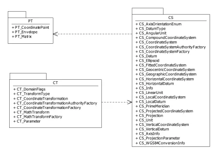
The interfaces for Coordinate Transformation Services are split into three packages:
a) Positioning (PT)
b) Coordinate Systems (CS) c) Coordinate Transformations (CT)
The interfaces in these packages have the following dependency relationships:
Package Interfaces depend on… PT None
CS PT
CT PT CS
Figure 1: Package interface dependencies
3.2 Naming
Conventions
All interfaces, structures and enumerations start with a two letter prefix indicating their package. For example, all interfaces in the Coordinate System package start with the prefix “CS_”. This convention both makes client code easier to understand, and resolves issues with re-using common names, e.g. Parameter.
All method, parameter and property names are consistent with the normal conventions for the DCP in question.
3.3 Object
Mutability
All interfaced objects are immutable. This means that implementations must promise not to change an object’s internal state once they have handed out an interface pointer.
All mutable entities are implemented with structures in the COM and CORBA profiles, and classes in the Java profile. These language elements allow for return-by-value and pass-by-value semantics.
3.4 Error
Handling
All errors are handled using the normal method for the DCP.
In the COM profile, an implementation that fails to perform an interface method can return a HRESULT value of E_FAIL. Successful method functions will return S_OK. In most COM client environments (e.g. Visual Basic and ATL C++) these return codes are processed by client-side stub code, and errors are converted into exceptions that the client application must catch. C client programmers should check all the HRESULT return values with the SUCCEEDED macro.
In the Java profile, an implementation that fails to perform an interface method should throw a runtime exception.
3.5 Mandatory
Parts
In order to make client software as easy as possible to write, all of the interfaces specified in each package are mandatory, with the exception of the ‘Authority’ factories. The reason for this is that if portions of the specification are optional, then, in practice, client software will be programmed to use only the mandatory parts.
For example, if an implementation were to implement the CS_CoordinateSystem interface, but not the CS_GeographicCoordinateSystem, CS_ProjectedCoordinateSystem, etc., interfaces, then the only way to establish the type of a CS_CoordinateSystem object would be to decode either the WKT or the XML.
This does not however mean that all portions of the specification have to be implemented. For example, an implementation could support the CS_CoordinateSystemFactory interface, but not support the createVerticalCoordinateSystem method.
In this version of the document, the XML Definition is ‘informative’, and is therefore optional.
See also Parameterized Transforms.
3.6
Constraints on Operation Sequencing
4
Coordinate System Identity
This specification uses two character strings for coordinate system identity. The first string identifies the “authority” or “nameSpace” that specifies multiple standard reference systems, e.g. “EPSG”. The second string specifies the “authority code” or “name” of a particular reference system specified by that authority. In the case of “EPSG”, the “authority code” will be a string representation of an integer. See CS_Info Class and Well-Known Text format: AUTHORITY.
5
Domains of Validity
Every GIS coordinate system, math transform, and coordinate transformation has a domain of validity, which is known as its ‘domain’.
For a GIS coordinate system, the domain is the set of coordinates that correspond to a position in the real world, to an acceptable level of accuracy.
For a math transform, the domain is the set of coordinate positions that can be transformed without mathematical problems, such as dividing by zero.
For a coordinate transformation, the domain can be imagined as the intersection of three domains: two domains from the source and target coordinate systems, and the domain of the math transform. (In fact, it's not quite this simple, since the intersection cannot be formed until the three domain shapes are in the same coordinate system.)
While working inside a single coordinate system, the domain is usually not critical. Since many GIS systems (but not all) use floating-point coordinates, you can place points slightly outside the coordinate system domain without causing any immediate problem. So the interface method to get the domain of a coordinate system can be quite simple. (See
CS_CoordinateSystem.getDefaultEnvelope.)
However, while transforming coordinates, the exact shape of these domains is often critical, since you cannot work outside them without problems, but you often want to work right up to the edges of them. Since math transform domains can, and often do have highly irregular shapes, it is not possible to have an interface method that returns the shape explicitly. Instead, the math transform domain is described implicitly. This means that you have to ask whether a particular ‘elementary shape’ is inside the domain, outside the domain, or partially inside and partially outside. The elementary shape that the CT_MathTransform interface uses is the convex hull. A convex hull is a shape in a coordinate system, where if two positions A and B are inside the shape, then all positions in the straight line between A and B are also inside the shape. So in 3D a cube and a sphere are both convex hulls. Other less obvious examples of convex hulls are straight lines, and single points. (A single point is a convex hull, because the positions A and B must both be the same - i.e. the point itself. So the straight line between A and B has zero length.)
Some examples of shapes that are NOT convex hulls are donuts, and horseshoes.
6 Profiles
All packages have been profiled for COM, CORBA and Java.
In order to make the different DCP profiles as compatible as possible, we have avoided using too many constructs. We have assumed that all DCPs have constructs for the following:
a) Atomic types of CharacterString, Boolean, Integer and Double b) Structures passed and returned by value
c) Fixed length arrays
d) Variable length sequences (including 2D)
e) Structures containing atomic types, arrays and structures
We have NOT used the following constructs:
a) Multiple Inheritance of interfaces b) Inheritance of structures
c) Native DCP dictionaries
d) Pass-by-value of entities with behavior e) Sequences of interfaces
6.1 COM
profile
The COM profile is specified in the attached MIDL files (see Appendix A: Interface Definition Files: COM). The files are named OGC_XX.IDL, where XX indicates the package name. (See
Naming Conventions.)
The dependencies between the packages are expressed using the MIDL keyword “import”.
6.1.1
Generating COM Type Libraries
Each MIDL file can be used to generate a type library (TLB) file by using the MIDL compiler as follows:
midl /D _OGC_PT_TLB_ OGC_PT.idl midl /D _OGC_CS_TLB_ OGC_CS.idl midl /D _OGC_CT_TLB_ OGC_CT.idl
These type libraries can be used to generate implementations, and they can be used by client-side application code that intends to discover server-client-side implementations at runtime.
6.1.2 COM
Categories
This specification includes several factory interfaces, which are used to create all the other COM objects. But how do client applications create these factories?
There are three methods:
a) Use the GUID of the chosen implementation’s co-class
b) Use the fully formed name of the chosen implementation’s co-class. c) Browse for available implementations of the category at runtime.
DEFINE_GUID(CATID_CS_CoordinateSystemFactory,
0x49937f54, 0x9921, 0x11d3, 0x81, 0x64, 0x0, 0xc0, 0x4f, 0x68, 0xf, 0xff);
DEFINE_GUID(CATID_CS_CoordinateSystemAuthorityFactory,
0x49937f53, 0x9921, 0x11d3, 0x81, 0x64, 0x0, 0xc0, 0x4f, 0x68, 0xf, 0xff);
DEFINE_GUID(CATID_CT_MathTransformFactory,
0x49937f52, 0x9921, 0x11d3, 0x81, 0x64, 0x0, 0xc0, 0x4f, 0x68, 0xf, 0xff);
DEFINE_GUID(CATID_CT_CoordinateTransformationFactory,
0x2ca0a8bd, 0xca5b, 0x11d3, 0x81, 0x98, 0x0, 0xc0, 0x4f, 0x68, 0xf, 0xff);
DEFINE_GUID(CATID_CT_CoordinateTransformationAuthorityFactory,
0x2ca0a8be, 0xca5b, 0x11d3, 0x81, 0x98, 0x0, 0xc0, 0x4f, 0x68, 0xf, 0xff);
6.2 CORBA
profile
The CORBA profile is specified in the attached CORBA IDL files (see Appendix A: Interface Definition Files: CORBA).
Each package is mapped to a CORBA module of the same name.
Two-dimensional arrays (e.g. matrices) are modeled with a sequence of sequences. All 2D arrays in this specification should be regular, so each sub-sequence in the 2D array should have the same length.
6.3 Java
profile
The Java profile is specified in the attached Java source files.
Each Java package is called “org.opengis.xx” where “xx” is the two-character package prefix in lower case.
The Java source includes tagged comments. These comments were used to generate the accompanying HTML documentation using the JavaDoc utility.
In the Java profile, structures are modeled with Java classes (e.g. PT_CoordinatePoint), and interfaces are used for entities that will have many different implementations (e.g.
CS_ProjectedCoordinateSystem).
This specification says that structures used as return values should use “return-by-value” semantics. This means that whenever a Java method has an object return type, the
implementation should create a new Java object. Since this is not very efficient, there are also pass-by-reference versions of heavily used functions (e.g. double[] transformList(double[] ord)).
7
Well-Known Text format
Many entities in this specification can be printed in a well-known text format. This allows objects to be stored in databases (persistence), and transmitted between interoperating computer programs.
Each entity has a keyword in upper case (for example, DATUM or UNIT) followed by the defining, comma-delimited, parameters of the object in brackets. Some objects are composed of objects so the result is a nested structure. Implementations are free to substitute standard brackets ( ) for square brackets [ ] and should be prepared to read both forms of brackets.
The definition for WKT is shown below using Extended Backus Naur Form (EBNF). The WKT for a math transform can be used inside a fitted coordinate system, so it is shown first.
7.1
Math Transform WKT
<math transform> = <param mt> | <concat mt> | <inv mt> | <passthrough mt> <param mt> = PARAM_MT["<classification name>" {,<parameter>}* ]
<parameter> = PARAMETER["<name>", <value>] <value> = <number>
<concat mt> = CONCAT_MT[<math transform> {,<math transform>}* ] <inv mt> = INVERSE_MT[<math transform>]
<passthrough mt> = PASSTHROUGH_MT[<integer>, <math transform>]
7.2
Coordinate System WKT
<coordinate system> = <horz cs> | <geocentric cs> | <vert cs> | <compd cs> | <fitted cs> | <local cs>
<horz cs> = <geographic cs> | <projected cs>
<projected cs> = PROJCS["<name>", <geographic cs>, <projection>, {<parameter>,}* <linear unit> {,<twin axes>}{,<authority>}] <projection> = PROJECTION["<name>" {,<authority>}]
<geographic cs> = GEOGCS["<name>", <datum>, <prime meridian>, <angular unit> {,<twin axes>} {,<authority>}]
<datum> = DATUM["<name>", <spheroid> {,<to wgs84>} {,<authority>}] <spheroid> = SPHEROID["<name>", <semi-major axis>, <inverse flattening>
{,<authority>}]
<semi-major axis> = <number> <inverse flattening> = <number>
<prime meridian> = PRIMEM["<name>", <longitude> {,<authority>}] <longitude> = <number>
<angular unit> = <unit> <linear unit> = <unit>
<unit> = UNIT["<name>", <conversion factor> {,<authority>}] <conversion factor> = <number>
<geocentric cs> = GEOCCS["<name>", <datum>, <prime meridian>, <linear unit> {,<axis>, <axis>, <axis>} {,<authority>}]
<authority> = AUTHORITY["<name>", "<code>"]
<vert cs> = VERT_CS["<name>", <vert datum>, <linear unit>, {<axis>,} {,<authority>}]
<compd cs> = COMPD_CS["<name>", <head cs>, <tail cs> {,<authority>}] <head cs> = <coordinate system>
<tail cs> = <coordinate system> <twin axes> = <axis>, <axis>
<axis> = AXIS["<name>", NORTH | SOUTH | EAST | WEST | UP | DOWN | OTHER] <to wgs84s> = TOWGS84[<seven param>]
<seven param> = <dx>, <dy>, <dz>, <ex>, <ey>, <ez>, <ppm> <dx> = <number>
<fitted cs> = FITTED_CS["<name>", <to base>, <base cs>] <to base> = <math transform>
<base cs> = <coordinate system>
<local cs> = LOCAL_CS["<name>", <local datum>, <unit>, <axis>, {,<axis>}* {,<authority>}]
<local datum> = LOCAL_DATUM["<name>", <datum type> {,<authority>}]
7.3
Description of WKT keywords
7.3.1 AUTHORITY
This is an optional clause that allows an external authority to manage the definition of an entity. Please see Referencing objects by ID versus Value for more details.
7.3.2 AXIS
The name of the axis is for human consumption. The enumerated value that follows is to allow software to correctly overlay different coordinate systems.
If the optional AXIS terms are not present, then the default values are assumed. They are Geographic Coordinate Systems: AXIS[“Lon”,EAST],AXIS[“Lat”,NORTH]
Projected Coordinate System: AXIS[“X”,EAST],AXIS[“Y”,NORTH]
Geocentric Coordinate System: AXIS[“X”,OTHER],AXIS[“Y”,EAST],AXIS[“Z”,NORTH]
However, if these terms are present, and have non-default values, then implementations must be prepared to swap and reverse the coordinates of geometry before attempting to overlay graphics.
7.3.3 COMPD_CS
This indicates a compound coordinate system, which combines the coordinate of two other coordinate systems. For example, a compound 3D coordinate system could be made up of a horizontal coordinate system and a vertical coordinate system.
7.3.4 CONCAT_MT
7.3.5 DATUM
This indicates the horizontal datum, which corresponds to the procedure used to measure positions on the surface of the Earth.
7.3.6 FITTED_CS
This indicates a fitted coordinate system.
The math transform is used to construct a map from the fitted coordinate system to the base coordinate system. The transform is often an affine map.
The math transform works from the fitted CS to the base CS so that the fitted CS can have a smaller dimension that the base CS. This is often quite useful. For example, a fitted coordinate system could be a 2D plane approximately tangential to the Earth, but based on a WGS84 geocentric 3D coordinate system.
7.3.7 GEOCCS
A 3D coordinate system, with its origin at the center of the Earth. The X axis points towards the prime meridian. The Y axis points East or West. The Z axis points North or South. By default the Z axis will point North, and the Y axis will point East (e.g. a right handed system), but you should check the axes for non-default values
7.3.8 GEOGCS
A coordinate system based on latitude and longitude. Some geographic coordinate systems are Lat/Lon, and some are Lon/Lat. You can find out which this is by examining the axes. You should also check the angular units, since not all geographic coordinate systems use degrees.
7.3.9 INVERSE_MT
A math transform defined as the inverse of another transform.
7.3.10 LOCAL_CS
This indicates a local, ungeoreferenced coordinate system. Such coordinate systems are often used in CAD systems. They can also be used for local surveys, where the relationship between the surveyed site and the rest of the world is not important.
The number of AXIS clauses indicates the dimension of the local coordinate system.
7.3.11 PARAMETER
A named projection parameter value.
The units of the parameter must be inferred from its context. If the parameter is inside a PROJCS, then its units will match the units of the PROJCS. If the parameter is inside a
PARAM_MT, then its units will be meters and degrees for linear and angular values respectively.
7.3.12 PARAM_MT
All the linear parameters are expressed in meters, and all the angular parameters are expressed in degrees. Other parameters should use S.I. units where possible. (E.g. use Kg for mass, and seconds for time.)
The <classification name> is a coded value that specifies the formulae used by the math transform. See Parameterized Transforms for legal values, and the corresponding parameters.
7.3.13 PASSTHROUGH_MT
This is a math transform that passes through a subset of ordinates to another transform. This allows transforms to operate on a subset of ordinates. For example, if you have (Lat,Lon,Height) coordinates, then you may wish to convert the height values from meters to feet without affecting the (Lat,Lon) values. If you wanted to affect the (Lat,Lon) values and leave the Height values alone, then you would have to swap the ordinates around to (Height,Lat,Lon). You can do this with an affine map.
The <integer> argument is the index of the first affected ordinate. The <math transform>
argument is the transform to pass coordinates onto.
7.3.14 PRIMEM
This defines the meridian used to take longitude measurements from. The units of the
<longitude> must be inferred from the context. If the PRIMEM clause occurs inside a GEOGCS, then the longitude units will match those of the geographic coordinate system. If the PRIMEM clause occurs inside a GEOCCS, then the units will be in degrees.
The longitude value defines the angle of the prime meridian relative to the Greenwich Meridian. A positive value indicates the prime meridian is East of Greenwich, and a negative value indicates the prime meridian is West of Greenwich.
7.3.15 PROJCS
This indicates a projected coordinate system. The PROJECTION sub-clause contains the classification name used by the CT_MathTransformFactory::CreateParameterizedTransform method, and the PARAMETER clauses specify the parameters. However, the units used by CT_MathTransformFactory are always meters and degrees, and the units in the PARAMETER clauses are in the linear/angular units of the PROJCS/GEOGCS respectively. So if you are writing code to read or write WKT, then you must use the IsParameterAngular and
IsParameterLinear methods to do the unit conversions - be careful!
(Notice that this handling of units is slightly different from the way the EPSG 4 database works. In the EPSG 4 database, each transformation parameter value defines its own units. However, 99% of the EPSG projection parameter units are the same as the units of the corresponding projected coordinate system.)
7.3.16 PROJECTION
This describes a projection from geographic coordinates to projected coordinates. It is used inside a PROJCS to define the parameters of the projection transform.
7.3.17 SPHEROID
“SPHEROID” is used in WKT for compatibility with Simple Features. However, the term “ellipsoid” is preferred elsewhere in this specification.
7.3.18 TOWGS84
This indicates a list of up to 7 Bursa Wolf transformation parameters. These parameters can be used to approximate a transformation from the horizontal datum to the WGS84 datum. However, it must be remembered that this transformation is only an approximation. For a given horizontal datum, different Bursa Wolf transformations can be used to minimize the errors over different regions.
If the DATUM clause contains a TOWGS84 clause, then this should be its “preferred”
transformation, which will often be the transformation which gives a broad approximation over the whole area of interest (e.g. the area of interest in the containing geographic coordinate system).
Sometimes, only the first three or six parameters are defined. In this case the remaining
parameters must be zero. If only three parameters are defined, then they can still be plugged into the Bursa Wolf formulas, or you can take a short cut. The Bursa Wolf transformation works on geocentric coordinates, so you cannot apply it onto geographic coordinates directly. If there are only three parameters then you can use the Molodenski or abridged Molodenski formulas.
The DATUM clause may not contain a TOWGS84 clause in the following situations:
a) The writing application was using the Simple Features specification, which does not specify TOWGS84 as a valid keyword
b) The writing application did not have an available transformation.
c) There is no possible transformation. For example, the horizontal datum could be a surface that rotates relative to the Earth’s surface.
In particular, if the DATUM does contain a TOWGS84 clause, and the parameter values are zero, then the receiving application can assume that the writing application believed that the datum is approximately equal to WGS84.
7.3.19 UNIT
This describes units used for values elsewhere within the parent WKT clause (sometimes including descendants of the parent clause).
The physical dimension (i.e. type) of the units is determined by context. For example, in a GEOGCS the type of the units is angular. In a VERT_CS the type of the units is linear.
Within a UNIT clause, the units are described by relating them to a fundamental unit of that type with a conversion factor. For linear units, the conversion factor is the scalar value that converts the described units into meters. For angular units, the conversion factor is the scalar value that converts the described units into radians.
7.3.20 VERT_DATUM
This indicates the vertical datum, or method used for vertical measurements.
7.3.21 VERT_CS
7.4
WKT Example
The following example shows a 3D compound coordinate system, which is made by combining a projected coordinate system and a vertical coordinate system. This is the same coordinate system as used for the XML Example.
PROJECTION["Transverse_Mercator"], PARAMETER["latitude_of_origin",49], PARAMETER["central_meridian",-2], PARAMETER["scale_factor",0.999601272], PARAMETER["false_easting",400000], PARAMETER["false_northing",-100000], UNIT[
8
Relationship to Simple Features
“Simple Features” is an earlier interface specification adopted by OGC. The Simple Features specification includes two packages: Geometry and Spatial Reference Systems (SRS).
The CS package in this specification covers the same ground as the Simple Features SRS package. The SRS package was based on a subset of the coordinate systems in the EPSG abstract model. The CS package extends this abstract model to encompass all EPSG coordinate systems, including vertical coordinate systems and compound coordinate systems. CS then goes further to handle more than 3 dimensions and ungeoreferenced coordinate systems.
8.1
Compatibility of Well-Known Text
The CS package keeps the WKT serializing concept of Simple Features SRS. In fact, all Simple Features SRS Well-Known Text strings are valid in CS, and have exactly the same
meaning. This ensures that all stored Simple Features SRS data will be compatible with the new CS package.
The Geographic Transform interface in the Simple Features SRS package has been absorbed into the CT package as a range of different math transforms (e.g. Molodenski). This does not affect WKT compatibility, since the WKT for geographic transformations was never defined.
8.2
Name changes from SF-SRS to CS
The CS package basically just renames all the Simple Features SRS interfaces by adding the “CS_” prefix, and then removes all the mutating methods. The functionality of the mutating methods (e.g. changing the longitude of a Prime Meridian) has been moved into the enlarged factory interfaces. A couple of the old Simple Features interfaces have been moved into other packages (see below).
Since most of the method names have been left unchanged from Simple Features, it is possible for objects to support both sets of interfaces. For example, a geographic coordinate system object (e.g. MyGCS) can easily support both CS_GeographicCoordinateSystem (from CS) and IGeographicCoordinateSystem (from SF). This means that the object MyGCS can be used with code that expects Simple Features interfaces or code that expects CS interfaces.
One notable name change is the method to get an entity’s well-known text. For example, in COM Simple Features this property was “WellKnownText”, whereas in CS the property is called “WKT”. This is done deliberately, so a new object which supports both SF and CS interfaces can tell whether it is being asked for an SF compatible WKT string, or a CS compatible WKT string. If it is asked for an SF compatible string then it should not include the new optional clauses. If the object is not part of the SF abstract model (e.g. a 3D coordinate system) then it should either not support the SF interfaces, or it should fail the WellKnownText method.
8.3 Authority
Codes
The CS and CT packages use a String for the Authority Code, whereas Simple Features used an Integer. This change was made for compatibility with those authorities that use String codes.
9 Processes
Common processes are shown here as scenarios. Some scenarios refer to previous scenarios, so you may find it convenient to read them in order.
9.1
Create a NAD27 California Zone 1 CS
In this example, a client wishes to get a coordinate system for California zone 1, based on the NAD27 geoid. The units of the coordinate system will be in feet.
The client does not know (or care) what projection this CS uses, let alone the correct parameter values to use for that projection. However, they do know the EPSG code, which is 26741.
1) Create a CS_CoordinateSystemAuthorityFactory
EPSG is a coordinate system “authority”, so firstly the client needs to create a CS_CoordinateSystemAuthorityFactory.
In the COM DCP they could write a loop to iterate through all the available
CS_CoordinateSystemAuthorityFactory implementations, testing each one to see if its authority name was “EPSG”.
In other DCPs, or if they knew the class name of the EPSG authority factory object within their implementation, they could dynamically create the object by name.
2) Use authority factory to create CS
In pseudo-code:
Dim csaf as CS_CoordinateSystemAuthorityFactory csaf = GetMyEpsgFactory()
dim cs as CS_CoordinateSystem
cs = csaf.CreateHorizontalCoordinateSystem(26741)
9.2
Create a NAD83 California Zone 1 CS
This process is identical to the process above, except that the EPSG code for a NAD83 projection is 26941. Also, the EPSG NAD83 coordinate system uses meters instead of feet.
9.3
Store and recall CS in a Database
The client may have lots of point data that uses coordinates in NAD27 California Zone 1. They can easily store the points in a two-column table, but how can they store the coordinate system and retrieve it later?
One solution would be to store the EPSG code of the CS (26741). But if they do this, then other software which does not know about EPSG, or which will not have an EPSG factory, will not be able to georeference the points correctly.
An alternative would be to store the CS in Well-Known Text format. (This is what the SQL92 schema of the Simple Feature specification does.)
Later, other software could read the WKT string and create their own CS object by using a CS_CoordinateSystemFactory as follows:
Dim csf as CS_CoordinateSystemFactory csf = GetMyCoordsysFactory()
Dim wkt as String
wkt = ReadWellKnownTextFromDB() dim cs as CS_CoordinateSystem cs = csf.CreateFromWKT(wkt)
Please notice that the above example uses a normal factory, and not an “authority” factory.
9.4
Merge California Zone 1 data in NAD27 and NAD83
If a client has an old table of California zone 1 points in NAD27 feet, and a new table of California zone 1 points in NAD83 meters, then they may want to merge the old table into the new table. To do this they will need to perform a coordinate transformation.
Firstly, the client can get WKT strings for the two coordinate systems. (If the WKT strings for the coordinate systems are stored with the point data, then they can skip this step.)
Secondly, the client can get a CT_CoordinateTransformation between the two coordinate systems. This will get details of the required transformation, but will not actually do any transforming operations.
Thirdly, the client can retrieve the CT_MathTransform from the CT_CoordinateTransformation.
Finally, the client can use the CT_MathTransform to transform the old point data into the NAD83 coordinate system, and then add the transformed points to the new table.
In pseudo code:
Rem Firstly get WKT of tables Dim wktOld as String
Dim wktNew as String wktOld = GetOldTableCS() wktNew = GetNewTableCS()
Rem Secondly get a transformation
Dim ctf as new CT_CoordinateTransformationFactory Dim ct as CT_CoordinateTransformation
ct = ctf.CreateFromCoordinateSystems( wktOld, wktNew )
Rem Thirdly retrieve the math transform Dim mt as CT_MathTransform
mt = ct.MathTransform
Rem Finally transform and merge the old points While (OldPointAvailable())
Dim ptOld as PT_CoordinatePoint ptOld.Ord.resize(2)
StoreNewPoint (ptNew.Ord[0], ptNew.Ord[1] ) End while
9.5
Transform steps from NAD27 to NAD83 in California Zone 1
The math transform used in the previous scenario contains many steps.
It is the job of the CT_CoordinateTransformationFactory to analyze the source and target coordinate systems to find a series of transform steps that will make up the complete transformation.
Here is a possible math transform for the previous scenario in Well-Known Text format:
(Embedded comments are shown in bold. These comments are not valid in WKT format, and are only included here to explain what the steps are doing.)
// Use concatenated transform CONCAT_MT[
// Use affine map to convert feet into meters. PARAM_MT["Affine",
PARAMETER["num_row",3], PARAMETER["num_col",3],
PARAMETER["elt_0_0",0.3048006096012192], PARAMETER["elt_0_1",0],
PARAMETER["elt_0_2",0], PARAMETER["elt_1_0",0],
PARAMETER["elt_1_1",0.3048006096012192], PARAMETER["elt_1_2",0],
PARAMETER["elt_2_0",0], PARAMETER["elt_2_1",0], PARAMETER["elt_2_2",1] ],
// Undo the California state plane projection. INVERSE_MT[
// Projection converts metres to (lon,lat). PARAM_MT["Lambert_Conformal_Conic_2SP",
PARAMETER["latitude_of_origin",41.66666666666662], PARAMETER["central_meridian",39.99999999999996], PARAMETER["standard_parallel_1",39.3333333333333], PARAMETER["standard_parallel_2",-121.9999999999999], PARAMETER["false_easting",609601.2192024385],
PARAMETER["false_northing",0], PARAM_MT["Affine",
PARAMETER["elt_2_1",0], PARAM_MT["Ellipsoid_To_Geocentric",
PARAMETER["semi_major",6378206.4], PARAMETER["semi_minor",6356583.8] ],
// Use affine map for Bursa Wolf transformation. PARAM_MT["Affine",
PARAMETER["num_row",4], PARAM_MT["Geocentric_To_Ellipsoid", PARAMETER["semi_major",6378137],
PARAMETER["semi_minor",6356752.314140356] ],
// Discard height, converting (lon,lat,hgt) into (lon,lat). PARAM_MT["Affine",
PARAMETER["num_row",3], PARAM_MT["Lambert_Conformal_Conic_2SP",
PARAMETER["central_meridian",39.99999999999996], PARAMETER["standard_parallel_1",39.3333333333333], PARAMETER["standard_parallel_2",-121.9999999999999], PARAMETER["false_easting",2000000],
PARAMETER["false_northing",500000], PARAMETER["semi_major",6378137],
PARAMETER["semi_minor",6356752.314140356] ]
10 Parameterized
Transforms
Many of the math transforms in the CT package are completely characterized by their
classification, or transform, name, e.g. “Transverse_Mercator”, and their parameter values. This allows these transforms to be implicitly serialized in foreign WKT strings (e.g. the PROJECTION clause in the CS WKT definition).
We expect that the list of classification names will grow to incorporate new transforms, as this Interface Specification is used in future specifications, or by different GIS/CAD market sectors. We encourage OGC to create and maintain a registry of transform classifications, and their parameters, and ideally their formulas.
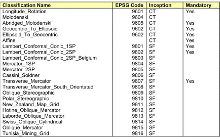
Here is an initial list of math transform classifications:
Classification Name EPSG Code Inception Mandatory
Longitude_Rotation 9601 CT Yes
Molodenski 9604 CT
Abridged_Molodenski 9605 CT Yes
Geocentric_To_Ellipsoid 9602 CT Yes
Ellipsoid_To_Geocentric 9602 CT Yes
Affine CT Yes
Lambert_Conformal_Conic_1SP 9801 SF Yes
Lambert_Conformal_Conic_2SP 9802 SF Yes
Lambert_Conformal_Conic_2SP_Belgium 9803 SF
Mercator_1SP 9804 SF
Mercator_2SP 9805 SF
Cassini_Soldner 9806 SF
Transverse_Mercator 9807 SF Yes
Transverse_Mercator_South_Orientated 9808 SF
Figure 2: Classifications of parameterized math transforms
The inception column shows when these classification names were first specified by OGC. So an inception of SF indicates that OpenGIS Simple Features first used the classification, and an inception of CT indicates that the classification was first used by this specification document.
10.1 Ellipsoid_To_Geocentric
Parameter Description
Semi_major Equatorial radius in meters
This transform operates on 3D coordinates. The first input ordinate is the longitude in degrees, and the second input ordinate is the latitude in degrees. The third input ordinate is the height above the ellipsoid in meters.
(These formulas and equations are copied from the EPSG 4.3 database.)
Latitude, P, and Longitude, L, in terms of Geographic Coordinate System (GCS) A may be expressed in terms of a geocentric (earth centered) Cartesian coordinate system X, Y, Z with the Z axis corresponding with the Polar axis positive northwards, the X axis through the intersection of the Greenwich meridian and equator, and the Y axis through the intersection of the equator with longitude 90 degrees E. If the GCS's prime meridian is not Greenwich, longitudes must first be converted to their Greenwich equivalent. If the earth's spheroidal semi major axis is a, semi minor axis b, and inverse flattening 1/f, then
XA= (nu + hA) cos P cos L YA= (nu + hA) cos P sin L ZA= ((1 - e^2) nu + hA) sin P
where nu is the prime vertical radius of curvature at latitude P and is equal to nu = a /(1 - e^2*sin^2(P))^0.5,
P and L are respectively the latitude and longitude (related to Greenwich) of the point
h is height above the ellipsoid, (topographic height plus geoidal height), and e is the eccentricity of the ellipsoid where e^2 = (a^2 -b^2)/a^2 = 2f -f^2
10.2
Geocentric_To_Ellipsoid
Parameter Description
semi_major Equatorial radius in meters
semi_minor Polar radius in meters
(These formulas and equations are copied from the EPSG 4.3 database.)
Cartesian coordinates in geocentric coordinate system B may be used
to derive geographical coordinates in terms of geographic coordinate system B by: P = arctan (ZB + e^2* nu*sin P) / (XB^2 + YB^2)^0.5 by iteration
L = arctan YB/XB
hB = XB sec L sec P - nu
where LB is relative to Greenwich. If the geographic system has a non Greenwich prime meridian, the Greenwich value of the local prime meridian should be applied to longitude.
values of -100m in the Sri Lanka area to +60m in the North Atlantic.)
10.3 Abridged_Molodenski
Parameter Description
dim Dimension of points (i.e. 2 or 3).
dx X shift in meters
dy Y shift in meters
dz Z shift in meters
src_semi_major Source equatorial radius in meters src_semi_minor Source polar radius in meters tgt_semi_major Target equatorial radius in meters tgt_semi_minor Target polar radius in meters
This transform can operate on 2D or 3D coordinates. In either case the first ordinate is the longitude in degrees, and the second ordinate is the latitude in degrees. In the 3D form the third ordinate is the height above the ellipsoid in meters.
As an alternative to the computation of the new latitude, longitude and height above ellipsoid in discrete steps through geocentric coordinates, the changes in these coordinates may be derived directly by formulas derived by Molodenski. Abridged versions of these formulas, which are quite satisfactory for three parameter transformations, are as follows:
(These formulas and equations are copied from the EPSG 4.3 database.)
Dlat " = [(-dX*sin(lat)*cos(lon)) - (dY*sin(lat)*sin(lon)) + (dZ*cos(lat)) + (((a*Df) + (f*Da))*sin(2*lat))] / (rho * sin(1"))
Dlon " = (-dX*sin(lon) + dY*cos(lon)) / ((nu*cos(lat)) * sin(1"))
Dh = (dX*cos(lat)*cos(lon)) + (dY*cos(lat)*sin(lon)) + (dZ*sin(lat)) + ((a*Df + f*Da)*(sin(lat)^2)) - Da
where the dX, dY and dZ terms are as before, and rho and nu are the meridian and prime vertical radii of curvature at the given latitude (lat) on the first ellipsoid (see section on
Geographic/Geocentric formulas), Da is the difference in the semi-major axes (a1 - a2) of the first and second ellipsoids and Df is the difference in the flattening of the two ellipsoids.
The formulas for Dlat and Dlon indicate changes in latitude and longitude in arc-seconds.
10.4 Affine
Affine maps are commonly used in coordinate transformations. An affine map can perform translation, rotations, scaling and shearing. In fact, any transformation that transforms all straight lines into straight lines is an affine map.
However, a classical matrix/vector product can only perform rotations – it cannot do translations. In order to do translations, the follow convention must be followed:
For a 2D affine map, the matrix is actually a 3 by 3 matrix, laid out as follows:
Axy Ayy Sy 0 0 1
The 2D position (X,Y) will be transformed to ( Axx*X + Ayx*Y + Sx, Axy*X + Ayy*Y + Sy).
You can think of this working as a normal matrix multiplication on the column vector (X, Y, 1). Notice that an extra vector element of 1 is added, to pick up the affine map’s transformation of (Sx,Sy). This means that the dimensions of the matrix are always one bigger than the
dimensions of the source/target coordinate systems.
This method of using matrices to define affine maps is extended to all dimensions.
Affine maps can also be used to define a Bursa Wolf transformation. The Bursa Wolf
transformation is applied to geocentric coordinates to model a change of datum. The formula is as follows:
Num_row Number of rows in matrix
Num_col Number of columns in matrix
elt_<r>_<c> Element of matrix
For the element parameters, <r> and <c> should be substituted by printed decimal numbers. The values of r should be from 0 to (num_row-1), and the values of s should be from 0 to (num_col-1).
Any undefined matrix elements are assumed to be zero for (r!=c), and one for (s==t). This corresponds to the identity transformation when the number of rows and columns are the same. The number of columns corresponds to one more than the dimension of the source coordinates and the number of rows corresponds to one more than the dimension of target coordinates. This means that the affine map can be applied to a point by multiplying its matrix on the left-hand side of the point’s vector. (There is another math convention where the matrix is used to the right of the vector, but here we are using the left-hand side convention.) The extra dimension in the matrix is used to let the affine map do a translation.
10.5 Longitude_Rotation
Parameter Description
dim Dimension of coordinates
rotation Rotation angle in degrees
This transform adds a constant onto longitude in (Lon,Lat) or (Lon,Lat,Hgt) coordinates. This is useful for handling changes in Prime Meridian.
be in degrees, in the range [-180,180). The latitude values should be in the range [-90,90]. If the latitude value is not in the range (-90,90), then the longitude should be 0. (For example, you should always use a longitude of zero for the North and South poles.) These rules apply to input and output longitude and latitude values.
• The longitude is assumed to be the first ordinate, and the latitude is assumed to be the second ordinate. Any subsequent ordinates are ignored, and should be left unchanged.
• This transform's derivative should be an identity matrix, except at points where the transform is discontinuous (i.e. the poles, and along two meridians).
10.6
Cartographic Projection Transforms
Cartographic projection transforms are used by projected coordinate systems to map geographic coordinates (e.g. Longitude and Latitude) into (X,Y) coordinates. These (X,Y) coordinates can be imagined to lie on a plane, such as a paper map or a screen.
All cartographic projection transforms will have the following properties:
• Converts from (Longitude, Latitude) coordinates to (X,Y)
• All angles are assumed to be degrees, and all distances are assumed to be meters.
• The domain should be a subset of {[-180,180)x(-90,90), (0,-90), (0,90)}.
10.6.1 Cartographic
Projection Transform Parameters
The valid parameters for the mandatory cartographic projection transforms are listed below. These include parameters for the semi-major and semi-minor axis of their ellipsoid in meters. These ellipsoid parameters can be skipped when the projection WKT is being embedded inside a Projected Coordinate System (see Well-Known Text format details), since the PCS ellipsoid will override the projection transform ellipsoid.
10.6.1.1 Transverse_Mercator Projection
Parameter Description of units semi_major Meters
semi_minor Meters
latitude_of_origin Degrees central_meridian Degrees
scale_factor No units
false_easting Meters false_northing Meters
10.6.1.2 Lambert_Conformal_Conic_1SP
Parameter Description of units semi_major Meters
semi_minor Meters
latitude_of_origin Degrees central_meridian Degrees
scale_factor No units
false_easting Meters false_northing Meters
10.6.1.3 Lambert_Conformal_Conic_2SP
Parameter Description of units semi_major Meters
semi_minor Meters
11
Referencing objects by ID versus Value
External authorities may be used to manage definitions of objects used in this Interface
Specification. The definitions of these objects are referenced using code strings. The codes and authority names can be embedded in WKT strings or XML, using an AUTHORITY clause.
If there is an AUTHORITY clause, and the reader recognizes the authority name, then the reader is entitled to use the authority’s definition, and ignore all the other values at that level in the definition. (How the reader consults the authority is outside the scope of this Interface Specification.)
To improve interoperability, writers of WKT and XML must always include a copy of all the values, as well as any AUTHORITY clause.
Readers will use the values (as opposed to the authority code) in the following cases:
1) There is no AUTHORITY clause
2) The reader does not recognize the authority
3) The reader fails to create an object using the authority code
The last case (where the reader recognizes the authority name, but fails to create an object using the code) can happen if the reader is using a different version of the authority from the writer.
In order to avoid misinterpretations, the following guidelines for authorities are recommended:
a) The authority name (or namespace) must be registered by OGC b) The authority must not reuse old code strings for “different” entities.
11.1
Registered WKT Authorities
We expect this part of the specification to be expanded as more authority names and name-spaces are registered with OGC.
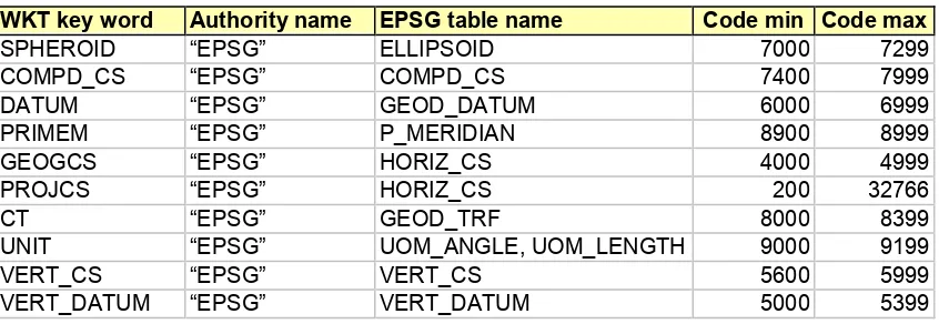
11.1.1 EPSG/POSC
The European Petroleum Survey Group maintains a database of spatial reference objects (see http://www.petroconsultants.com/products/geodetic.html). The IDs of these objects are currently used in the GeoTIFF specification, and the OGC Web Mapping Testbed interfaces.
WKT key word Authority name EPSG table name Code min Code max
SPHEROID “EPSG” ELLIPSOID 7000 7299
COMPD_CS “EPSG” COMPD_CS 7400 7999
DATUM “EPSG” GEOD_DATUM 6000 6999
PRIMEM “EPSG” P_MERIDIAN 8900 8999
GEOGCS “EPSG” HORIZ_CS 4000 4999
PROJCS “EPSG” HORIZ_CS 200 32766
CT “EPSG” GEOD_TRF 8000 8399
UNIT “EPSG” UOM_ANGLE, UOM_LENGTH 9000 9199
VERT_CS “EPSG” VERT_CS 5600 5999
VERT_DATUM “EPSG” VERT_DATUM 5000 5399
12 UML
Documentation
The specified interfaces have been modeled in the Unified Modeling Language in a DCP independent manner. If you have software for reading UML files then you may wish to use it to examine the attached UML model file (with file extension MDL).
Please note that the UML model is automatically generated from the Java interface source files. The conversion program follows some simple rules that define, for example, how to model the dependencies between classes. Although this approach is very good for keeping the UML model and all of the profiles consistent (the COM and CORBA Interface Definition Files are also
automatically generated from the Java source files), the resulting UML model is less sophisticated than one created by hand.
12.1 Packages
PT
+ P T_C o ordinatePoint + P T_En v elope
+ C S_C ompoundC oordinateSy stem + C S_C oordinateSy stem
+ C S_C oordinateSy stemA uthority Factory + C S_C oordinateSy stemFactory + C S_Datum
+ C S_Ellipsoid
+ C S_FittedC oordinateSy stem + C S_GeocentricC oordinateSy stem + C S_GeographicC oordinateSy stem + C S_HorizontalC oordinateSy stem + C S_HorizontalDatum
+ C S_Info + C S_LinearUnit
+ C S_LocalC oordinateSy stem + C S_LocalDatum
+ C S_PrimeMeridian
+ C S_ProjectedC oordinateSy stem + C S_Projection
+ C S_Unit
+ C S_VerticalC oordinateSy stem + C S_VerticalDatum
+ C S_A xisInfo
+ C S_ProjectionParameter + C S_W GS84C onv ersionInfo C T
+ C T_DomainFlags + C T_TransformTy pe
+ C T_C oordinateTransformation
+ C T_C oordinateTransformationA uthority Factory + C T_C oordinateTransformationFactory + C T_MathTransform
+ C T_MathTransformFactory + C T_Parameter