PHOTOGRAMMETRIC ACCURACY AND MODELING OF ROLLING SHUTTER
CAMERAS
Jonas Vautherin, Simon Rutishauser, Klaus Schneider-Zapp, Hon Fai Choi, Venera Chovancova, Alexis Glass and Christoph Strecha
Pix4D SA, EPFL Innovation Park Building D, CH-1015 Lausanne [email protected]
KEY WORDS:Mapping, Motion Estimation, Rolling Shutter Modeling, CMOS, UAVs, Drones
ABSTRACT:
Unmanned aerial vehicles (UAVs) are becoming increasingly popular in professional mapping for stockpile analysis, construction site monitoring, and many other applications. Due to their robustness and competitive pricing, consumer UAVs are used more and more for these applications, but they are usually equipped with rolling shutter cameras. This is a significant obstacle when it comes to extracting high accuracy measurements using available photogrammetry software packages. In this paper, we evaluate the impact of the rolling shutter cameras of typical consumer UAVs on the accuracy of a 3D reconstruction. Hereto, we use a beta-version of the Pix4Dmapper 2.1 software to compare traditional (non rolling shutter) camera models against a newly implemented rolling shutter model with respect to both the accuracy of geo-referenced validation points and to the quality of the motion estimation. Multiple datasets have been acquired using popular quadrocopters (DJI Phantom 2 Vision+, DJI Inspire 1 and 3DR Solo) following a grid flight plan. For comparison, we acquired a dataset using a professional mapping drone (senseFly eBee) equipped with a global shutter camera. The bundle block adjustment of each dataset shows a significant accuracy improvement on validation ground control points when applying the new rolling shutter camera model for flights at higher speed (8 m/s). Competitive accuracies can be obtained by using the rolling shutter model, although global shutter cameras are still superior. Furthermore, we are able to show that the speed of the drone (and its direction) can be solely estimated from the rolling shutter effect of the camera.
1. INTRODUCTION
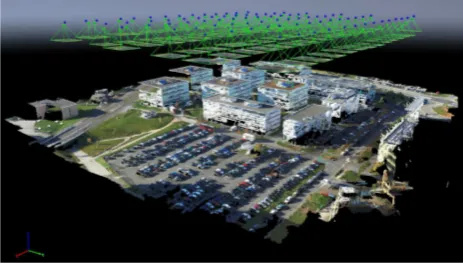
There is an increasing interest in using small consumer drones for photogrammetric applications including mapping and three-dimensional (3D) reconstruction of small to medium-sized areas, such as quarries, construction or cultural heritage sites, agricul-ture, and the mapping of city districts. The main advantages of consumer drones are low cost, good portability, ease of use, and high flexibility. At the same time, they are still capable of provid-ing results with competitive accuracy. Fig. 1 shows an example of a small-area 3D reconstruction using a consumer drone.
These small drones are equipped with camera sensors that de-liver images with a quality comparable to state of the art compact cameras. As their principal application is aerial cinematography, however, they typically are not equipped with a global shutter but rely instead on an electronic rolling shutter readout of their complementary metal-oxide-semiconductor (CMOS) sensor. In a rolling shutter readout, the sensor is exposed and read line-by-line, instead of the entire image being exposed at once. This can lead to additional distortions when imaging fast-moving objects or when imaging using a fast-moving or vibrating camera.
In order to map large areas efficiently, mapping drones need to fly as fast as possible – typically up to10 m/sat altitudes of50 m above ground. At such speeds and without appropriate model-ing, distortions due to the rolling shutter limit the accuracy of the photogrammetric reconstruction, as we show in this paper (Sec-tion 5.).
A considerable body of research in the photogrammetry and com-puter vision community has focused on modeling the rolling shut-ter for various purposes. For instance, it was shown that the rolling shutter effect can be leveraged in order to simultaneously estimate the position and velocity of moving objects (Ait-Aider et al., 2006, Magerand and Bartoli, 2010). Substantial attention has been dedicated to compensating for rolling shutter artifacts in videos. This includes various approximations for modeling
the effect of the camera motion on the image by means of affine transforms (Chun et al., 2008, Baker et al., 2010), a global motion model (Liang et al., 2008), a mixture of homographies (Grund-mann et al., 2012), and modeling the camera motion as a pure rotation with constant angular velocity (Hedborg et al., 2011). Most of these approaches do not explicitly model the camera tion and are thus not appropriate for precise structure from mo-tion reconstrucmo-tions where the camera is known to move at high speed.
Rolling shutter modeling in photogrammetry and structure from motion applications typically presumes a constant translational and rotational velocity during the exposure of each video frame or still image. For instance, (Klein and Murray, 2009) estimate velocities for each keyframe from neighboring video frames and precompensate the interest point locations. These are optimized along with the velocities in a bundle adjustment step, which also optimizes the velocities and thus has six additional degrees of freedom per camera. However, if all the frames in a video are used in a reconstruction, then only six additional motion
Figure 2: Evaluated drones: DJI Inspire 1 (top-left), DJI Phantom 2 Vision+ (top-right), 3DR Solo with GoPro HERO4 (bottom-left) and senseFly eBee (bottom-right, used as a reference with a global shutter camera).
ters are required for the entire video (Hedborg et al., 2012), when linearly interpolating the camera pose between frames. In other studies, information from inertial measurement units (IMUs) were applied to infer the motion during exposure (Li et al., 2013), an approach which has also been proposed for photogrammetry (Colomina et al., 2014). As these descriptions model the cam-era velocity during exposure, the additional information can si-multaneously be used to estimate motion blur in order to obtain more consistent feature extraction and matching (Meilland et al., 2013). More recently, a minimal solver for retrieving a linear ap-proximation of the rotation and translation velocities during ex-posure along with the camera pose has been proposed (Albl et al., 2015).
In the following sections, we show that for mapping applications with small unmanned aerial vehicles (UAVs) using a controlled flight plan (see Fig. 3), a rolling shutter model describing the drone translation velocity during the exposure of each frame is sufficient to compensate for the motion-induced rolling shutter artifacts and preserve mapping accuracy even at high speed. To this purpose we will evaluate the accuracy of reconstruction using a set of consumer UAVs (as shown in Fig. 2) for the acquisition of images which are processed with and without a rolling shutter model.
Section 2. gives more details about the different shutter technolo-gies found in contemporary cameras. Section 3. describes the rolling shutter model that is used for this paper. Our experimen-tal setup is outlined in Section 4. and evaluated in Section 5.
2. GLOBAL AND ROLLING SHUTTERS
A great variety of combinations of mechanical and electronic global and rolling shutters can be found in today’s consumer and professional cameras. The most common ones are:
• mechanical rolling shuttersin most interchangeable lens dig-ital single lens reflex (DSLR) systems,
• mechanical global shuttersin most consumer compact cam-eras with non-removable lenses and many photogrammetry cameras,
• electronic global shuttersin older DSLRs with charge cou-pled device (CCD) sensors, as well as in cameras with CMOS-type sensors in some specialized applications such as high-speed cameras,
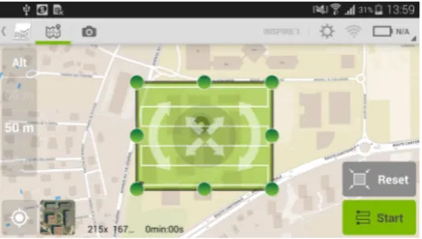
Figure 3: Mission planning in Pix4Dcapture, depicted here for the Inspire 1. The App controls taking the pictures, yielding very similar datasets for the different drones. The drone will follow the path represented by the white line in the green selection area. We used the "high overlap" setting of Pix4Dcapture.
• electronic rolling shuttersfor still imaging in compact con-sumer products such as smartphones, very compact action cameras, consumer UAVs; this is also the capture mode used for video capture in all DSLRs and consumer compact cam-eras.
Mechanical global shutters are “central shutters” that are located inside the lens. Central shutters are found in consumer cam-eras with non-removable lenses (Canon Ixus S110, Fuji X100 and many more) as well as in photogrammetry camera systems (such as the Leica RC30, Hasselblad A5D). Central shutters are diaphragms consisting of between six and twelve blades. The maximum shutter speed may depend on the aperture setting, but is typically1/1000 sor slower.
Mechanical rolling shutters, on the other hand, are found in all common DSLR camera systems. They consist of two shutter cur-tains located just in front of the sensor – a first curtain that is opened to start the exposure, followed by a second curtain that ends it. This system is very attractive for interchangeable-lens camera systems – only the camera needs a shutter, not each lens, and the shutter speeds can be much shorter (as low as1/8000 s for many cameras). At slow shutter speeds, the first curtain is lowered and the entire sensor is illuminated for most of the ex-posure time. At very fast shutter speeds, however, both shutter curtains are moving simultaneously, exposing only a small frac-tion of the image at any time. The rolling-shutter readout time for these systems is the time needed for one shutter curtain to pass over the entire image – it is about half the flash synchroniza-tion time specified by the camera manufacturer (not counting any special high-speed flash modes). For a DSLR, this time is on the order of2 msand thus more than an order of magnitude shorter than the readout time of most electronic rolling shutters.
t
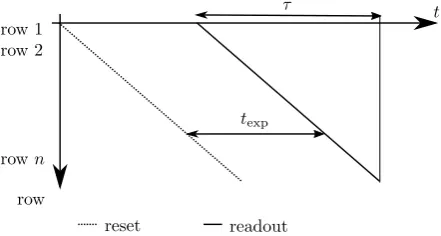
Figure 4: Rolling shutter readout scheme. The sensor is reset line by line at constant speed. One line is read simultaneously. After the exposure timetexp, the sensor starts the read-out line by line. At timet= 0the first row of the sensor is reset. It is read out at timet=texp. Consecutive lines are reset and read out one after the other. The sensor readout is finished after the rolling shutter readout timeτ.
older digital cameras (Nikon D70 and D200, Olympus E1) or in cameras dedicated to still imaging such as the Leica M9. In most of these systems, the option of using a global electronic shutter is, if at all, only used at very short shutter speeds beyond the limit of the mechanical shutter.
Over the last few years, CCDs have been replaced more and more by CMOS-type image sensors in most consumer electronics ap-plications, including cell phones, compact cameras as well as DSLRs. CMOS sensors had been catching up with CCDs since the advent of active-pixel CMOS sensors in the early 1990s (Fos-sum, 1993), as step by step they overcame their initial problems with dark-current and other types of noise. In CMOS sensors, the photodiode converting incident light into charge is equivalent to the one found in a CCD sensor, but the charge is converted into a current and amplified directly by three or four transistors located in each pixel. The pixel values can then be read out using a flexible matrix addressing scheme that is implemented as transistor logic, as opposed to the much less flexible CCD charge shifting registers. This allows for fast readout of parts of the sensor to create low-resolution high-framerate videos and live previews, easier pixel-binning electronics, and also enables the camera to efficiently remeasure and adjust exposure, white-balance and autofocus by performing additional reads of a few pixels in between frames (Nakamura, 2005, Sec. 5.1.3). Addi-tional advantages compared to CCD sensors include up to an or-der of magnitude lower power consumption (CCDs need15 V to 20 Vto realize buried-channel charge transfer), and the use of standard CMOS fabrication processes leading to lower fabri-cation costs and enabling the integration of on-chip processing electronics, starting with (but not limited to) the analog-digital conversion. However, CCDs are still the first choice for many scientific applications, where low noise, uniform response and high dynamic range are the primary requirements – the trade-offs involved in the sensor choice for a specific application are dis-cussed in (Litwiller, 2001).
Unlike CCDs, standard CMOS image sensors do not store the charge independently of the photodiode. In order to avoid using the costly, large and error-prone mechanical shutter in consumer electronics such as mobile phones, action cameras like the Go-Pro HERO, and many consumer drones, a rolling shutter readout scheme is widely used with CMOS sensors. This purely elec-tronic shutter is especially important for video capture, as me-chanical diaphragm shutters only can support a limited number of actuations. In a rolling shutter readout, the sensor is reset and read out line-by-line (Nakamura, 2005, Fig. 5.6). The readout
time for each frame is constant and independent of the exposure parameters, whereas the exposure time is set by the delay be-tween reset and readout of each line as shown in Fig. 4. In most sensors, one line is read out and processed simultaneously. The voltages in the active pixels are transferred via column-parallel programmable gain amplifiers (PGAs), digitized in analogue dig-ital converters (ADC), and the results stored in a line buffer. This parallel approach has the advantage of high speed and low power consumption due to low sampling rates. For most consumer cam-eras, the rolling shutter frame readout takes on the order of30 ms to 40 ms, which is the longest readout time that still enables capturing videos at 30 or 25 frames per second, respectively. This relatively slow rolling shutter readout can lead to artifacts when capturing fast-moving objects or when recording images and videos from moving cameras mounted on UAVs.
Electronic global shutters have also been implemented for CMOS type sensors, but they are much less widely used, due to the need for more complex circuitry in each pixel. Thus CMOS-type elec-tronic global shutter sensors are currently manufactured only with moderate pixel counts and densities, mostly for applications in cameras with extremely high frame rates.
3. PHOTOGRAMMETRIC ROLLING SHUTTER MODEL
For any frame camera we can express the projection of a 3D world pointX by the internal and external camera parameters. The set of internal parameters are assumed to be constant for all images of the project. They are modeling the projection of a per-spective or a fisheye lens with a mathematical description. The external parameters are different for each image and describe the image position and orientation. A 3D pointX = (X, Y, Z,1) is projected into an image at a homogeneous pixel locationx= (λx, λy, λz)for a global shutter model by
x=π[R| −Rc]X, (1)
where the lens is described by its internal parametersπand the position and orientation of the camera is given by the rotation matrixR and camera centerc. The internal parameters of the camera model are described in (Strecha et al., 2015).
In the case of a rolling shutter model, the camera performs an unknown general movement during the readout of the sensor. To account for this motion, the projection equation can be expressed using a time-dependent positionc(t)and orientationR(t)of the camera
x=π[R(t)| −R(t)c(t) ]X (2)
At timet= 0the first row of the sensor is processed for readout and the camera center is atc(0)and oriented according toR(0). All 3D pointsXthat project onto the first row of the sensor are modeled using positionc(0)and orientationR(0). Until the read-out of the sensor is finished at timeτthe camera has moved to a new locationc(τ)with orientationR(τ).
Drone Camera Resolution Shutter Sensor Lens Field of Est. readout
[pixels] type view [◦] time [ms]
DJI Phantom 2 Vision+ FC200 4384×3288 Rolling 1/2.3”CMOS Fisheye 110/80 74
DJI Inspire 1 FC300X 4000×3000 Rolling 1/2.3”CMOS Perspective 85/70 30
3DR Solo GoPro 4 Black 4000×3000 Rolling 1/2.3”CMOS Fisheye 125/95 30
senseFly eBee Canon S110 4000×3000 Global 1/1.7”CMOS Perspective 71/56
-Table 1: Specifications of the evaluated cameras and their estimated readout time. The field of view denotes the horizontal/vertical field of view as we measure it. The FC300X has a20 mmlens and the Canon S110 has a zoom lens set to24 mm(both in35 mmformat equivalent). The readout time estimations coming from our model have been confirmed by DJI for the FC200 and FC300X cameras.
it intonequally spaced sectors, each of them corresponding to one set ofcj, Rj. The motion of the camera during readout can then be modeled by
R(t) =R0·∆Rj (3)
for the rotation and by
c(t) =c0+ ∆cj, (4)
for the translation, where∆Rjis the incremental rotation at sec-torjof the sensor, relative to the rotation at the beginning of the exposure, and∆cjis the incremental translation.
An even simpler linear model that describes the rolling shutter effect using only6parameters is given by:
R(t) =R0·λ∆R (5)
for the rotation and by
c(t) =c0+λ∆c, (6)
for the translation, whereλ ∈ [−1,1]models the time (image row) and2·∆cand2·∆Ris the linear motion during the readout timeτ.
4. EXPERIMENTAL SETUP
4.1 Data acquisition
We evaluated rolling shutter cameras on board three popular con-sumer drones. As reference, we used a professional mapping drone with a global shutter compact camera. The drones are de-picted in Fig. 2 while the properties of their respective cameras are listed in Table 1.
We acquired datasets above our test site with office buildings (Fig. 1). On-site, 12 ground control points (GCPs) have been measured at high precision as shown in Table 2. For each UAV, we made datasets at different speeds at the same altitude of70 m above ground using Pix4Dcapture (depicted in Fig. 3) for flight planning and control. The on-board measurements of the drone (e.g. speed and global positioning system (GPS) location) and the time of image capture were transmitted to the App and saved for further processing. This gave us access to the drone’s velocity estimate during the capture of each image.
The reference global shutter dataset was captured with the sense-Fly eBee. In this case, the altitude was chosen such that the ground sampling distance (GSD) was similar to that achieved us-ing the consumer drones. The eBee was controlled usus-ing sense-Fly eMotion.
4.2 Evaluation
The datasets were processed with Pix4Dmapper 2.1 beta. Six of the 12 GCPs were used in the processing to georeference the reconstruction, while the remaining 6 were used as verification points. Because of occlusions (several GCPs are situated on a parking lot), some datasets only have 5 verification points. The software calculated the position and orientation of each camera, the errors of the verification points, and a georeferenced point cloud. Each dataset was processed with and without the rolling shutter model. For the processing with the model enabled, the fitted parameters of the rolling shutter model (namely the lin-ear translation vector during the exposure) were saved for further analysis.
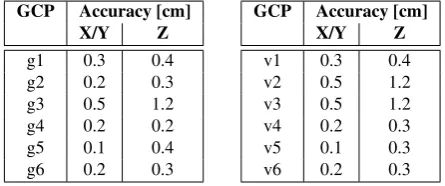
Table 2: Accuracy of the ground control and validations points used in our experiments. Points g3, v2, v3 are on a building roof (see Fig. 7 for a map). All other points have increased accuracy due to an additional tachimetric adjustment.
5. RESULTS
The results are consistent across all evaluated datasets. For rolling shutter cameras, higher flying speed and slower readout time lead to a greater improvement from the rolling shutter model. The ref-erence dataset from the global shutter camera has the same results with and without using the rolling shutter model.
For the rolling shutter cameras, the motion estimate of the rolling shutter model as fitted by the bundle block adjustment correlates well with the flight path and is very close to the motion vector estimated from on-board drone measurements, showing that the rolling shutter effect is correctly modeled. Fig. 6 shows the mo-tion vectors for the Phantom 2 flying at8 m/sas well as for the eBee. For the Phantom 2, the reference motion vectors were cal-culated from the on-board measured drone speed and the esti-mated rolling shutter readout time (see Tab. 1). For the eBee, the rolling shutter model results in random vectors with nearly zero length, because it is a global shutter camera for which the model is not applicable. For the consumer drones, outliers at the ends of the flight lines stem from the drone rotating before moving to the next flight line, as only a linear translation is modeled.
#
measurements
0 40 80 100
0 5 10 15 a)
#
measurements
Estimated readout time [ms]
0 40 60 80
0 5 10 15 b)
Figure 5: Estimated readout time for each image of the Phantom 2 Vision+ at8 m/s(a) and Inspire 1 at8 m/s(b) datasets. The median value for the Phantom 2 is74 ms(DJI confirmed73 ms). The readout time of the Inspire 1 is much faster, with an estimated value of30 ms(DJI confirmed33 ms). Most of the outliers cor-respond to images taken at the end of a flight line, because the drone rotates to move to the next line. Results are consistent with the other datasets, with more noise in the datasets taken at lower speed, as one would expect.
vector estimated from the rolling shutter model by the on-board measured drone speed. Results are shown in Fig. 5 and Table 1. The numbers are consistent between the different datasets of the same drone at different speeds. Flights at slower speed show more noise.
An estimation of the displacement of image content during the rolling shutter readout timeτ due to the UAV’s forward velocity can be obtained by
∆y≈vτ sy
ϕyh with ϕy=
Sy
f (7)
where∆yis the vertical displacement in pixels,vis the drone ve-locity in meters per second,syis the vertical image size in pixels, ϕyis the vertical camera field of view in radians,his the flight height above ground in meters,Sythe vertical sensor size in me-ters andfthe focal length in meters. For a DJI Phantom 2 flying at8 m/sand70 mabove ground, the rolling shutter causes a dis-placement of about10pixels. For a DJI Inspire 1, on the other hand, the displacement is only about4pixels, thanks largely to the much shorter readout time.
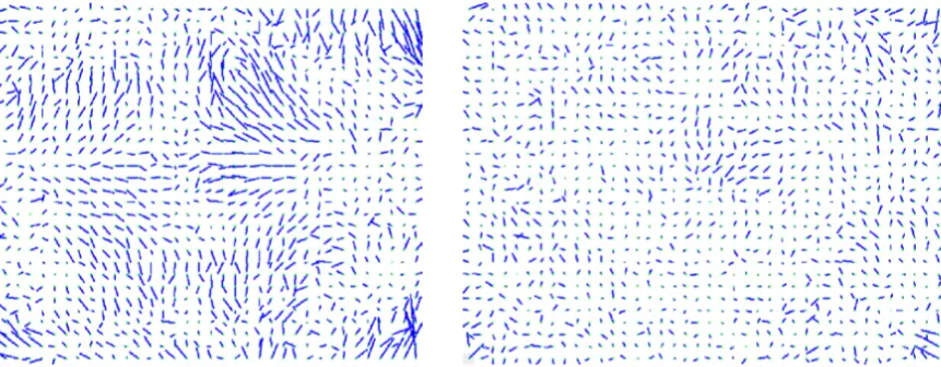
Fig. 8 shows the direction and magnitude of the average repro-jection error in the Phantom 2 Vision+ camera for the dataset flown at8 m/s. The left image shows results from the traditional global shutter camera model, the right one from the rolling shut-ter camera model. The errors with the rolling shutshut-ter model are much smaller. A systematic error appears only with the tradi-tional model, but is eliminated with the rolling shutter model, which confirms that the rolling shutter is correctly modeled.
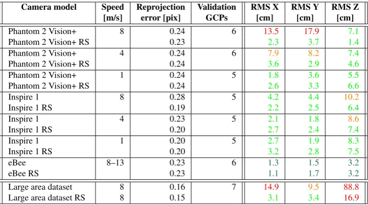
Table 3 shows the average root mean-square (RMS) error of the verification points for each dataset. A graphical representation
50m a)
50m b)
Figure 6: Motion of the drone during the acquisition of the im-ages as estimated by the rolling shutter model. Each arrow repre-sents a picture. The length of the arrows is proportional to the motion of the drone during the readout time and upscaled for readability. The motions as estimated from the on-board drone measurements and from the rolling shutter model are displayed in blue and black respectively. (a) Results for the eBee dataset with a global shutter camera show very small estimated displace-ments in random directions. (b) Results for the Phantom 2 Vi-sion+ dataset at8 m/s.
of the X-Y components of the errors is shown in Fig. 7. Here the circle depicts the mean ground sampling distance of2.85 cm and the GCPs used for georeferencing the reconstruction are rep-resented by red crosses. The rolling shutter model significantly improves the accuracy of the validation points for rolling shut-ter datasets at medium to high speeds, while the influence at low speed is smaller. For the Phantom, only the slowest dataset is not significantly affected by the rolling shutter effect, whereas for the Inspire 1, only the high speed dataset is visibly influenced. This is due to the much shorter readout time of the Inspire 1 camera.
For the global shutter camera on board the eBee, the rolling shut-ter model has no influence on the accuracy. The verification points located at the center of the grid are more accurate than the ones close to the border, which can be explained by the fact that there is a GCP close to them, and that their central position makes them visible in more images.
v1
g1 g2
g3
v2 v3
g4
v4
g5
v5 v6
g6
50 m 50 m
Figure 7: Error of the verification points, both for the reconstruction without (left) and with (right) the rolling shutter model. The red crosses depict the GCPs. The arrows are centered on the verification points and their lengths and directions show the X-Y error for each of the datasets listed in Tab. 3. The circle centered on each verification point shows the GSD in the same scale as the arrows. On the left image, the rectangle shows the contours of the flight path.
that are densely distributed over the entire mapping area. For our test site, selecting five GCPs surrounding the area will reduce the errors within this area to a similar extent as can be obtained by correctly modeling the rolling shutter. The errors outside the area surrounded by GCPs can, however, only be reduced by modeling the rolling shutter effect. Furthermore, constructing such a high GCP density is both time and work intensive and hence not prac-tical for most large surveying projects. For example, the large area dataset of a city district as shown in Fig. 11 covers an area of half a square kilometer, surrounded by 7 GCPs. In this case, the error on the checkpoints situated in the interior of the survey area is also considerably improved when using the rolling shutter model, as shown in the last rows of Table 3 and Fig. 9.
88.8
Phantom 2 Inspire 1 eBee
0
Figure 9: RMS error for Phantom, Inspire, eBee and the large dataset from Table. 3. In gray and dark-blue are the errors for the classical and rolling shutter model, respectively.
[
k
m
2 ]
Phantom 2 Inspire 1 eBee
8 m/
Figure 10: Approximate estimation of the maximum surface that can be covered using a single battery charge by the UAVs at dif-ferent speeds.
Figure 11: Large data set reconstruction using Pix4Dmapper 2.1. It was created from 1700 images captured in several flights us-ing a DJI Phantom 2 Vision+. It covers an area of half a square kilometer with a ground sampling distance of3.4 cm.
6. CONCLUSIONS
Consumer drones are becoming increasingly useful for photogram-metric mapping applications. However, care has to be taken when flying at higher speeds because of the rolling shutter effect. For the Phantom 2 Vision+, a popular consumer drone often used for surveying, the results obtained in this paper indicate an ap-proximate upper bound for the flight speed of4 m/sto reach re-sults that are compatible with the well accepted practical accuracy bound of1−2GSD inX/Y and2−3GSD in Z direction. For the Inspire 1, this limit is shifted toward8 m/ssince the readout time for its sensor is much faster.
This demonstrates that the speed limitation imposed by rolling shutter cameras represents a practical obstacle towards their use in photogrammetric mapping when it is not compensated for. It limits the maximal speed at which the drone can be flown, and hence the area that can be mapped with the same battery life (see Fig. 10), constraining the productivity that surveyors can attain when using UAVs. However, as this study demonstrated, explicitly modeling the rolling shutter effect of the camera, as implemented in Pix4Dmapper 2.1, allows this speed limit to be increased. We have shown that in this case, the accuracy is not affected by the rolling shutter distortions even if we reach flight speeds of8 m/s.
An additional advantage of explicitly modeling the rolling shut-ter is the ability to estimate the drone speed purely based on the image content. This adds the future possibility, when photogram-metry can be applied in real-time, to fuse the estimate of rolling shutter speed with data from the other sensors to enhance the state estimation of a UAV.
The results obtained with a global shutter camera, as carried by the professional senseFly eBee, still outperform the ones based on a rolling shutter camera, but require substantially more expen-sive equipment. Nevertheless, our observations show that con-sumer drones with rolling shutter cameras can attain good perfor-mance at a lower cost when the rolling shutter effect is correctly modeled. Hence, having this additional enhancement available in photogrammetry software such as Pix4Dmapper 2.1 will fur-ther improve the usability of low-cost and light-weight UAVs for professional mapping applications.
REFERENCES
Camera model Speed Reprojection Validation RMS X RMS Y RMS Z [m/s] error [pix] GCPs [cm] [cm] [cm]
Phantom 2 Vision+ 8 0.24 6 13.5 17.9 7.1
Phantom 2 Vision+ RS 0.23 2.3 3.7 1.4
Phantom 2 Vision+ 4 0.24 6 7.9 8.2 7.4
Phantom 2 Vision+ RS 0.24 3.6 2.9 4.6
Phantom 2 Vision+ 1 0.24 5 1.8 3.6 5.5
Phantom 2 Vision+ RS 0.24 2.6 3.3 6.6
Inspire 1 8 0.28 5 4.2 4.4 10.2
Inspire 1 RS 0.19 2.2 2.5 6.4
Inspire 1 4 0.23 5 2.1 1.8 8.6
Inspire 1 RS 0.20 2.7 2.4 7.4
Inspire 1 1 0.20 5 2.7 1.9 8.3
Inspire 1 RS 0.20 3.2 2.8 7.5
eBee 8–13 0.23 6 1.3 1.5 3.2
eBee RS 0.23 1.1 1.7 3.2
Large area dataset 8 0.16 7 14.9 9.5 88.8
Large area dataset RS 8 0.15 3.1 3.4 16.9
Table 3: Comparison of the camera models with and without rolling shutter (RS) block adjustment for various cameras and flight speeds recorded at our test site. Of the 12 GCPs available, 6 were used for the calibration and 5-6 were used as validation GCPs (one was sometimes occluded). The GSD of the datasets is always around2.85 cm. The RMS error is reported on the validation GCPs. For the RMS errors, the following color coding was applied: horizontal X and Y axes: green≤2 GSD<orange≤3 GSD<red; vertical Z axis: green≤3 GSD<orange≤4 GSD<red. The large area dataset is the one shown in Fig. 11
view from a rolling shutter camera. In: Computer Vision–ECCV 2006, Springer, pp. 56–68.
Albl, C., Kukelova, Z. and Pajdla, T., 2015. R6p - rolling shutter absolute pose problem. In: Computer Vision and Pattern Recog-nition (CVPR), 2015 IEEE Conference on, pp. 2292–2300.
Baker, S., Bennett, E., Kang, S. B. and Szeliski, R., 2010. Re-moving rolling shutter wobble. In: Computer Vision and Pat-tern Recognition (CVPR), 2010 IEEE Conference on, IEEE, pp. 2392–2399.
Chun, J.-B., Jung, H. and Kyung, C.-M., 2008. Suppressing rolling-shutter distortion of cmos image sensors by motion vector detection. Consumer Electronics, IEEE Transactions on 54(4), pp. 1479–1487.
Colomina, I., Blázquez, M., Gauss, A. C. F. and de la Tecnolo-gia, P. M., 2014. Pose versus state: are sensor position and at-titude sufficient for modern photogrammetry and remote sens-ing? ISPRS-International Archives of the Photogrammetry, Re-mote Sensing and Spatial Information Sciences 1(1), pp. 33–37.
Fossum, E. R., 1993. Active pixel sensors: Are CCDs dinosaurs? In: IS&T/SPIE’s Symposium on Electronic Imaging: Science and Technology, International Society for Optics and Photonics, pp. 2–14.
Grundmann, M., Kwatra, V., Castro, D. and Essa, I., 2012. Calibration-free rolling shutter removal. In: Computational Pho-tography (ICCP), 2012 IEEE International Conference on, IEEE, pp. 1–8.
Hedborg, J., Forssén, P.-E., Felsberg, M. and Ringaby, E., 2012. Rolling shutter bundle adjustment. In: Computer Vision and Pattern Recognition (CVPR), 2012 IEEE Conference on, IEEE, pp. 1434–1441.
Hedborg, J., Ringaby, E., Forssén, P.-E. and Felsberg, M., 2011. Structure and motion estimation from rolling shutter video. In: Computer Vision Workshops (ICCV Workshops), 2011 IEEE In-ternational Conference on, IEEE, pp. 17–23.
Klein, G. and Murray, D., 2009. Parallel tracking and map-ping on a camera phone. In: Mixed and Augmented Real-ity, 2009. ISMAR 2009. 8th IEEE International Symposium on, IEEE, pp. 83–86.
Li, M., Kim, B. H., Mourikis, A. et al., 2013. Real-time mo-tion tracking on a cellphone using inertial sensing and a rolling-shutter camera. In: Robotics and Automation (ICRA), 2013 IEEE International Conference on, IEEE, pp. 4712–4719.
Liang, C.-K., Chang, L.-W. and Chen, H. H., 2008. Analysis and compensation of rolling shutter effect. Image Processing, IEEE Transactions on 17(8), pp. 1323–1330.
Litwiller, D., 2001. CCD vs. CMOS: Facts and fiction. Photonics Spectra.
Magerand, L. and Bartoli, A., 2010. A generic rolling shutter camera model and its application to dynamic pose estimation. In: International symposium on 3D data processing, visualiza-tion and transmission.
Meilland, M., Drummond, T., Comport, A. et al., 2013. A unified rolling shutter and motion blur model for 3d visual registration. In: Computer Vision (ICCV), 2013 IEEE International Confer-ence on, IEEE, pp. 2016–2023.
Nakamura, J., 2005. Image sensors and signal processing for digital still cameras. CRC press.
Strecha, C., Zoller, R., Rutishauser, S., Brot, B., Schneider-Zapp, K., Chovancova, V., Krull, M. and Glassey, L., 2015. Quality as-sesment of 3d reconstruction using fisheye and perspective sen-sors. ISPRS Annals of the Photogrammetry, Remote Sensing and Spatial Information Sciences II-3/W4, pp. 215–222.
ACKNOWLEDGEMENTS