ABSTRAK
Perkembangan dalam bidang industri dewasa ini semakin maju. Sebagian
besar bidang industri telah menggunakan teknologi otomasi industri, pengendalian
mesin-mesin industri telah dilakukan dengan menggunakan PLC karena memberi
banyak keuntungan. Keuntungan yang diperoleh dengan menggunakan PLC,
antara lain waktu implementasi proyek lebih cepat, perubahan rancangan dapat
dengan mudah dilakukan ( menggunakan software PLC ), dan perawatannya
mudah. Selain itu, pengendalian mesin-mesin industri dengan menggunakan PLC
tidak terbatas pada satu merek PLC.
Pengendalian dengan PLC dapat dilakukan dengan software SCADA
(Supervisory Control and Data Acquisition), yang dapat menampilkan proses
yang sedang berlangsung. Salah satu software SCADA adalah Citect
HMI/SCADA. Dengan menggunakan software Citect HMI/SCADA,
pengendalian dengan menggunakan berbagai merek PLC dapat dilakukan.
Pada tugas akhir ini, PLC yang digunakan adalah PLC Twido dan PLC
Omron. Plant simulasi yang digunakan adalah plant simulasi pengendalian
pencampuran, plant simulasi pengendalian temperatur dan plant simulasi lift.
Aplikasi software Citect HMI/SCADA berhasil dilakukan untuk PLC Twido dan
PLC Omron, dan pengalamatannya sesuai dengan alamat masing-masing PLC.
Waktu respon plant untuk PLC omron menggunakan software Citect
HMI/SCADA berkisar antara 0,214 sampai 0,22 detik, sedangkan untuk PLC
ABSTRACT
Industrial’s development nowadays increases rapidly. Most industrial
areas have used industrial automation technology, operation industrial
machineries have been done by using PLC because giving many advantages. The
advantages by using PLC, for example quicker project implementation time,
change of design can easily done (using PLC software), and easy maintenance.
Besides, operation of industrial machineries using PLC do not limited to one
brand of PLC.
Operation using PLC can be done with SCADA (Supervisory Control and
Data Acquisition) software, which can show present process. One of SCADA
software is Citect HMI/SCADA. Operation using various brand of PLC can be
done by Citect HMI/SCADA software.
In this final project, PLCs which are used are Twido PLC and Omron
PLC. Simulation Plants which is used are mixing control plant simulator,
temperature control plant simulator, and lift plant simulation. Application of
Citect HMI/SCADA software is done successfully for Twido PLC and Omron
PLC, and its addressing is same according to each PLCs. Response time of plant
for Omron PLC using Citect HMI/SCADA software range from 0.214 to 0.22
DAFTAR ISI
I.2 Identifikasi Masalah ... 1
I.3 Tujuan ... 1
II.1.1.2 Modul Masukan/Keluaran (Peralatan Input/Output) ... 7
II.1.1.3 Memori ... 8
II.1.2 Bahasa Pemrograman Untuk PLC ... 9
II.1.3 Sistem Operasi PLC ... 9
II.1.4 Konsep Pemrograman PLC ... 10
II.2 PLC Twido ... 11
II.2.1 Alokasi Memori ... 12
II.2.2 Input/Output (I/O) Section ………... 12
II.2.2.1 Fixed I/O ………... 13
II.2.2.2 Modular I/O ... 13
II.2.3 Twidosoft ... 13
II.2.4.1 Protokol Remote Link ... 15
II.3.3 CX-Programmer ... 25
II.4 Citect HMI/SCADA ... 26
II.4.1 Konfigurasi Environment ... 27
II.4.1.1 Citect Explorer ………. 27
II.4.1.2 Citect Project Editor ……… 28
II.4.1.3 Citect Graphics Builder ... 29
II.4.1.4 Cicode Editor ... 30
II.4.2 Sistem Runtime ... 31
II.5 Controller ... 32
II.5.1 Open-Loop Controller ... 33
II.5.2 Closed-Loop Controller ... 33
II.5.3 Proportional Controller ... 34
II.5.4 Integral Controller ... 36
II.5.5 Derivative Controller ... 38
II.5.6 PID Controller ... 40
BAB III PERANCANGAN DAN REALISASI ... 42
III.1 Pengendalian Proses Pada Plant Simulasi ... 42
III.1.1 Plant Simulasi Pengendalian Pencampuran ... 43
III.1.1.1 Cara Kerja Plant Simulasi Pengendalian Pencampuran ... 43
III.1.1.2 Pemetaan I/O Plant Simulasi Pengendalian Pencampuran ... 44
III.1.2 Plant Simulasi Pengendalian Temperatur ... 46
III.1.2.1 Cara Kerja Plant Simulasi Pengendalian Temperatur ... 46
III.1.2.2 Pemetaan I/O Plant Simulasi Pengendalian Temperatur ... 47
III.1.2.3 Flowchart Plant Simulasi Pengendalian Temperatur ... 47
III.1.3 Plant Simulasi Lift ... 49
III.1.3.1 Cara Kerja Plant Simulasi Lift ... 49
III.1.3.2 Pemetaan I/O Plant Simulasi Lift ... 50
III.1.3.3 Flowchart Plant Simulasi Lift ... 50
III.2 Pemrograman PLC Master Twido ... 53
III.2.1 Pemrograman Pengendalian Start-Stop PLC Slave ... 54
III.2.2 Pemrograman Request ke PLC Slave ... 55
III.2.2.1 Request Read N Words ke PLC Slave 1 ... 55
III.2.2.2 Request Write N Words ke PLC Slave 1 ... 55
III.2.2.3 Request Read N Words ke PLC Slave 2 ... 56
III.2.2.4 Request Write 1 Word ke PLC Slave 2 ... 57
III.2.3 Pemrograman Urutan Transmisi ... 57
III.3 Pemrograman Software Citect HMI/SCADA ... 58
III.3.1 Pembuatan Tabel Alamat Memori ... 58
III.3.2 Perancangan Tampilan Animasi HMI ... 61
BAB IV HASIL PENGAMATAN ... 63
IV.1 Uji Coba Start Stop dari PLC Master Twido ... 63
IV.2 Uji Coba Tombol dari PLC Omron ... 64
IV.3 Uji Coba Proses Melalui Software Citect HMI/SCADA ... 67
IV.3.1 Uji Coba Start Stop pada PLC Twido ... 67
IV.3.2 Uji Coba Tombol pada PLC Omron ... 69
LAMPIRAN B
LAMPIRAN C
DAFTAR GAMBAR
Gambar II.1 Komposisi PLC ... 6
Gambar II.2 Blok Diagram PLC ... 6
Gambar II.3 Blok Diagram CPU PLC ... 7
Gambar II.4 Scan Time PLC ... 10
Gambar II.5 Bentuk Fisik PLC Twido Compact dan Modular ... 12
Gambar II.6 Format Request Read N Bits ……….. 16
Gambar II.7 Format Request Read N Words ……….. 17
Gambar II.8 Format Request Write 1 Bit ……… 17
Gambar II.9 Format Request Write 1 Word ……… 18
Gambar II.10 Format Request Write N Bits ……… 18
Gambar II.11 Format Request Write N Words ……… 19
Gambar II.12 Bentuk Fisik CPU CPM1A ... 20
Gambar II.13 Gambar Komunikasi 1:1 ke Komputer ... 23
Gambar II.14 Gambar Komunikasi 1:N Host Link ... 23
Gambar II.15 Gambar komunikasi NT Link ... 24
Gambar II.16 Gambar komunikasi PC link ... 25
Gambar II.17 Tampilan dari CX-Programmer Environment ... 26
Gambar II.18 Tampilan dari Citect Explorer ... 28
Gambar II.19 Tampilan dari Citect Project Editor ... 29
Gambar II.20 Tampilan dari Citect Graphics Builder ... 30
Gambar II.21 Tampilan dari Cicode Editor ... 31
Gambar II.22 Tampilan dari Layar Runtime ... 32
Gambar II.23 Blok Diagram Umpan Balik Sederhana ... 34
Gambar II.24 Diagram Blok Poportional Controller ... 34
Gambar II.25 Proportional Band dari Proportional Controller tergantung pada penguatan ... 35
Gambar II.27 Blok Diagram Hubungan antara Besaran Kesalahan
dengan Integral Controller... 37
Gambar II.28 Perubahan Keluaran sebagai akibat Penguatan dan Kesalahan .. 37
Gambar II.29 Blok Diagram Derivative Controller ... 38
Gambar II.30 Kurva Waktu Hubungan Input-Output Derivative Controller ... 39
Gambar II.31 Blok Diagram PID Controller ... 40
Gambar II.32 Hubungan dalam Fungsi Waktu antara Sinyal Keluaran dengan Masukan untuk PID Controller ... 40
Gambar III.1 Gambar Blok Diagram Pengendalian ... 42
Gambar III.2 Plant Simulasi Pengendalian Pencampuran ... 43
Gambar III.3 Flowchart Plant Simulasi Pengendalian Pencampuran ... 45
Gambar III.4 Plant Simulasi Pengendalian Temperatur ... 46
Gambar III.5 Flowchart Plant Simulasi Pengendalian Temperatur ... 48
Gambar III.6 Plant Simulasi Lift ... 49
Gambar III.7 Flowchart Utama Plant Simulasi Lift ... 51
Gambar III.8 Flowchart A Plant Simulasi Lift ... 52
Gambar III.9 Flowchart B Plant Simulasi Lift ... 52
Gambar III.10 Flowchart C Plant Simulasi Lift ... 53
Gambar III.11 Request Read N Words ke PLC Slave 1 ... 55
Gambar III.12 Request Write N Words ke PLC Slave 1 ... 56
Gambar III.13 Request Read N Words ke PLC Slave 2 ... 56
Gambar III.14 Request Write 1 Word ke PLC Slave 2 ... 57
Gambar III.15 Blok Diagram Urutan Transmsi Request ... 58
Gambar III.16 Tampilan Animasi HMI Plant yang Menggunakan PLC Twido ... 61
Gambar III.17 Tampilan Animasi HMI Plant yang Menggunakan PLC Omron ... 62
Gambar IV.1 Tampilan Animasi Plant Simulasi yang Menggunakan PLC Twido ... 72
Gambar IV.2 Tampilan Animasi Plant Simulasi yang Menggunakan PLC Omron ... 73
Gambar IV.4 Trending Temperatur Plant Simulasi Pengendalian
Temperatur dengan Kp=5000, Ti=500, dan Td=0 ... 75
Gambar IV.5 Trending Temperatur Plant Simulasi Pengendalian
Temperatur dengan Kp=4000, Ti=750, dan Td=0 ... 75
Gambar IV.6 Trending Temperatur Plant Simulasi Pengendalian
Temperatur dengan Kp=3000, Ti=0, dan Td=500 ... 76
Gambar IV.7 Trending Temperatur Plant Simulasi Pengendalian
Temperatur dengan Kp=3500, Ti=1500, dan Td=300 ... 77
Gambar IV.8 Trending Temperatur Plant Simulasi Pengendalian
Temperatur dengan Kp=3250, Ti=1000, dan Td=125 ... 77
.
.
DAFTAR TABEL
Tabel II.1 Area Memori CPU CPM1A ... 22
Tabel III.1 Memori Proses Plant Simulasi Pengendalian Temperatur ... 59
Tabel III.2 Memori Proses Plant Simulasi Pengendalian Pencampuran ... 60
Tabel III.3 Memori Proses Plant Simulasi Lift ... 60
Tabel IV.1 Percobaan Push Button Start Plant Simulasi Pengendalian Temperatur ... 63
Tabel IV.2 Percobaan Push Button Stop Plant Simulasi Pengendalian Temperatur ... 63
Tabel IV.3 Percobaan Push Button Start Plant Simulasi Pengendalian Pencampuran ... 64
Tabel IV.4 Percobaan Push Button Stop Plant Simulasi Pengendalian Pencampuran ... 64
Tabel IV.5 Percobaan Tombol Lantai 0 Pada Plant Simulasi Lift ... 65
Tabel IV.6 Percobaan Tombol Lantai 1 Pada Plant Simulasi Lift ... 65
Tabel IV.7 Percobaan Tombol Lantai 2 Pada Plant Simulasi Lift ... 65
Tabel IV.8 Percobaan Tombol Dalam Lift 0 Pada Plant Simulasi Lift ... 66
Tabel IV.9 Percobaan Tombol Dalam Lift 1 Pada Plant Simulasi Lift ... 66
Tabel IV.10 Percobaan Tombol Dalam Lift 2 Pada Plant Simulasi Lift ... 66
Tabel IV.11 Percobaan Start Plant Simulasi Pengendalian Temperatur Melalui Software SCADA ... 67
Tabel IV.12 Percobaan Stop Plant Simulasi Pengendalian Temperatur Melalui Software SCADA ... 68
Tabel IV.13 Percobaan Start Plant Simulasi Pengendalian Pencampuran Melalui Software SCADA ... 68
Tabel IV.14 Percobaan Stop Plant Simulasi Pengendalian Pencampuran Melalui Software SCADA ... 69
Tabel IV.15 Percobaan Tombol Lantai 0 Pada Plant Simulasi Lift yang Ditampilkan Pada Software Citect HMI/SCADA ... 69
Tabel IV.17 Percobaan Tombol Lantai 2 Pada Plant Simulasi
Lift yang Ditampilkan Pada Software Citect HMI/SCADA ... 70
Tabel IV.18 Percobaan Tombol Dalam Lift 0 Pada Plant Simulasi
Lift yang Ditampilkan Pada Software Citect HMI/SCADA ... 70
Tabel IV.19 Percobaan Tombol Dalam Lift 1 Pada Plant Simulasi
Lift yang Ditampilkan Pada Software Citect HMI/SCADA ... 71
Tabel IV.20 Percobaan Tombol Dalam Lift 2 Pada Plant Simulasi
LAMPIRAN A
Plant Simulasi Pengendalian Temperatur
Plant Simulasi Pengendalian Pencampuran
Training Kit Omron
A)
LAMPIRAN B
LADDER DIAGRAM
PLC MASTER TWIDO
LADDER DIAGRAM
PLANT SIMULASI PENGENDALIAN TEMPERATUR
LADDER DIAGRAM
LAMPIRAN C
Presentation of the different types of communication
At a Glance
Twido provides one or two serial communications ports used for communications to remote I/O controllers, peer controllers, or general devices. Either port, if available, can be used for any of the services, with the exception of
communicating with Twido Soft, which can only be performed using the first port. Three different base protocols are supported on each Twido controller: Remote Link, ASCII, or Modbus (modbus master or modbus slave).
Moreover, the TWDLCAE40DRF compact controller provides one RJ-45 Ethernet communications port. It supports the Modbus TCP/IP client/server protocol for peer-to-peer communications between controllers over the Ethernet network.
Remote Link
The remote link is a high-speed master/slave bus designed to communicate a small amount of data between the master controller and up to seven remote (slave) controllers. Application or I/O data is transferred, depending on the configuration of the remote controllers. A mixture of remote controller types is possible, where some can be remote I/O and some can be peers.
ASCII
The ASCII protocol is a simple half-duplex character mode protocol used to transmit and/or receive a character string to/from a simple device (printer or terminal). This protocol is supported only via the "EXCH" instruction.
Modbus
The Modbus protocol is a master/slave protocol that allows for one, and only one, master to request responses from slaves, or to act based on the request. The master can address individual slaves, or can initiate a broadcast message to all slaves. Slaves return a message (response) to queries that are addressed to them individually. Responses are not returned to broadcast queries from the master. Modbus master - The modbus master mode allows the Twido controller to send a modbus query to a slave and await its reply. The modbus master mode is
supported only via the "EXCH" instruction. Both Modbus ASCII and RTU are supported in modbus master mode.
Modbus Slave - The modbus slave mode allows the Twido controller to respond to modbus queries from a modbus master, and is the default communications mode if no other type of communication is configured. The Twido controller supports the standard modbus data and control functions and service extensions for object access. Both Modbus ASCII and RTU are supported in modbus slave mode.
Note: 32 devices (without repeaters) can be installed on an RS-485 network (1 master and up to 31 slaves), the addresses of which can be between 1 and 247.
Modbus TCP/IP
Note: Modbus TCP/IP is solely supported by TWDLCAE40DRF series of compact controllers with built-in Ethernet network interface.
The following information describes the Modbus Application Protocol (MBAP). The Modbus Application Protocol (MBAP) is a layer-7 protocol providing peer-to-peer communication between programmable logic controllers (PLCs) and other nodes on a LAN.
The current Twido controller TWDLCAE40DRF implementation transports Modbus Application Protocol over TCP/IP on the Ethernet network. Modbus protocol transactions are typical request-response message pairs. A PLC can be both client and server depending on whether it is querying or answering
messages.
Modbus Communications
Introduction
The Modbus protocol is a master-slave protocol that allows for one, and only one, master to request responses from slaves, or to act based on the request. The master can address individual slaves, or can initiate a broadcast message to all slaves. Slaves return a message (response) to queries that are addressed to them individually. Responses are not returned to broadcast queries from the master.
CAUTION
UNEXPECTED EQUIPMENT OPERATION
Be sure that there is only one Modbus master controller on the bus and that each Modbus slave has a unique address. Failure to observe this precaution may lead to corrupted data or unexpected and ambiguous results.
Be sure that all Modbus slaves have unique addresses. No two slaves should have the same address. Failure to observe this precaution may lead to corrupted data or unexpected and ambiguous results.
Failure to follow this instruction can result in injury or equipment damage.
Hardware Configuration
A Modbus link can be established on either the EIA RS-232 or EIA RS-485 port and can run on as many as two communications ports at a time. Each of these ports can be assigned its own Modbus address, using system bit %S101 and system words %SW101 and %SW102. .
The table below lists the devices that can be used:
1 Base controller supporting a 3-wire EIA RS-485 port with a miniDIN connector.
TWDNOZ232D 2 Communication module equipped with a 3-wire EIA RS-232 port with a miniDIN connector. Note: This module is only available for the Modular controllers. When the module is attached, the controller cannot have an Operator Display expansion module.
TWDNOZ485D 2 Communication module equipped with a 3-wire EIA RS-485 port with a miniDIN connector. Note: This module is only available for the Modular controllers. When the module is attached, the controller cannot have an Operator Display expansion module.
TWDNOZ485T 2 Communication module equipped with a 3-wire EIA RS-485 port with a terminal.
Note: This module is only available for the Modular controllers. When the module is attached, the controller cannot have an Operator Display expansion module.
TWDNAC232D 2 Communication adapter equipped with a 3-wire EIA RS-232 port with a miniDIN connector. Note: This adapter is only available for the Compact 16, 24 and 40 I/O controllers and the Operator Display expansion module.
TWDNAC485D 2 Communication adapter equipped with a 3-wire EIA RS-485 port with a miniDIN connector. Note: This adapter is only available for the Compact 16, 24 and 40 I/O controllers and the Operator Display expansion module.
TWDNAC485T 2 Communication adapter equipped with a 3-wire EIA RS-485 port with a terminal connector. Note: This adapter is only available for the Compact 16, 24 and 40 I/O controllers and the Operator Display expansion module.
TWDXCPODM 2 Operator Display expansion module equipped with a 3-wire EIA RS-232 port with a miniDIN connector, a 3-wire EIA RS-485 port with a miniDIN connector and a 3-wire EIA RS-485 port with a terminal.
Note: This module is only available for the Modular controllers. When the module is attached, the controller cannot have a Communication expansion module.
Note: The presence and configuration (RS232 or RS485) of Port 2 is checked at power-up or at reset by the firmware executive program.
Nominal Cabling
Nominal cable connections are illustrated below for both the EIA RS-232 and the EIA RS-485 types.
Note: If port 1 is used on the Twido controller, the DPT signal on pin 5 must be tied to the circuit common (COM) on pin 7. This signifies to the Twido controller that the communications through port 1 is Modbus and is not the protocol used to communicate with the TwidoSoft software.
The cable connections made to each remote device are shown below.
EIA RS-485 Line Polarization on TWDLCA• 40DRFControllers
There is no internal pre-polarization in TWDLCA• 40DRF controllers. Therefore, external line polarization is required when connecting the TWDLCA• 40DRF Modbus master controller to the EIA-485 Modbus network.
(When there is no data activity on an EIA-485 balanced pair, the lines are not driven and, therefore, susceptible to external noise or interference. To ensure that its receiver stays in a constant state, when no data signal is present, the Modbus
master device needs to bias the network via external line polarization.)
Note: EIA RS-485 external line polarization must be implemented on the Modbus Master controller only; you must not implement it on any slave device.
The external line polarization assembly on the TWDLCA• 40DRF mini-DIN RS-485 EIA line shall consist in:
One pull-up resistor to a 5V voltage on D1(A+) circuit,
One pull-down resistor to the common circuit on D0(B-) circuit.
The following figure illustrates the external line polarization assembly on the TWDLCA• 40DRF mini-DIN RS-485 EIA line:
External polarization can be performed in any of two ways:
Connecting externally the user-provided polarization assembly via mini-DIN fly cable. (Please refer to pin definition for connector.)
Using a polarization tap (configured for 2-wire polarization) and polarization assembly (available soon from the catalog).
Software Configuration
To configure the controller to use a serial connection to send and receive characters using the Modbus protocol, you must:
Step Description
1 Configure the serial port for Modbus using TwidoSoft.
2 Create in your application a transmission/reception table that will be used by the EXCHx instruction.
Configuring the Port
A Twido controller can use its primary port 1 or an optionally configured port 2 to use the Modbus protocol. To configure a serial port for Modbus:
Step Action
1 Define any additional communication adapters or modules configured to the base.
2 Right-click on the port and click Edit Controller Comm Setup... and change serial port type to "Modbus".
3 Set the associated communication parameters.
Modbus Master
Modbus master mode allows the controller to send a Modbus query to a slave, and to wait for the response. The Modbus Master mode is only supported via the EXCHx instruction. Both Modbus ASCII and RTU are supported in Modbus Master mode.
The maximum size of the transmitted and/or received frames is 250 bytes. Moreover, the word table associated with the EXCHx instruction is composed of the control, transmission and reception tables.
Most significant byte Least significant byte
Command Length (Transmission/Reception) Control table
Reception offset Transmission offset Transmitted Byte 1 Transmitted Byte 2 Transmission table
... ...
... Transmitted Byte n
Transmitted Byte n+1
Received Byte 1 Received Byte 2 Reception table
... ...
... Received Byte p
Received Byte p+1
Note: In addition to queries to invidual slaves, the Modbus master controller can initiate a broadcast query to all slaves. The command byte in case of a boradcast query must be set to 00, while the slave address must be set to 0.
Control table
The Length byte contains the length of the transmission table (maximum 250 bytes), which is overwritten by the number of characters received at the end of the reception, if reception is requested.
This parameter is the length in bytes of the transmission table. If the Tx Offset parameter is equal to 0, this parameter will be equal to the length of the
transmission frame. If the Tx Offset parameter is not equal to 0, one byte of the transmission table (indicated by the offset value) will not be transmitted and this parameter is equal to the frame length itself plus 1.
The Command byte in case of Modbus RTU request (except for broadcast) must always equal to 1 (Tx and Rx).
The Tx Offset byte contains the rank (1 for the first byte, 2 for the second byte, and so on) within the Transmission Table of the byte to ignore when transmitting the bytes. This is used to handle the issues associated with byte/word values within the Modbus protocol. For example, if this byte contains 3, the third byte would be ignored, making the fourth byte in the table the third byte to be transmitted.
The Rx Offset byte contains the rank (1 for the first byte, 2 for the second byte, and so on) within the Reception Table to add when transmitting the packet. This is used to handle the issues associated with byte/word values within the Modbus protocol. For example, if this byte contains 3, the third byte within the table would be filled with a ZERO, and the third byte was actually received would be entered into the fourth location in the table.
Transmission/reception tables
When using either mode (Modbus ASCII or Modbus RTU), the Transmission table is filled with the request prior to executing the EXCHx instruction. At execution time, the controller determines what the Data Link Layer is, and performs all conversions necessary to process the transmission and response. Start, end, and check characters are not stored in the Transmission/Reception tables.
Once all bytes are transmitted, the controller switches to reception mode and waits to receive any bytes.
Reception is completed in one of several ways:
timeout on a character or frame has been detected, end of frame character(s) received in ASCII mode,
the Reception table is full.
Transmitted byte X entries contain Modbus protocol (RTU encoding) data that is to be transmitted. If the communications port is configured for Modbus ASCII, the correct framing characters are appended to the transmission. The first byte contains the device address (specific or broadcast), the second byte contains the function code, and the rest contain the information associated with that function code.
Note: This is a typical application, but does not define all the possibilities. No validation of the data being transmitted will be performed.
Received Bytes X contain Modbus protocol (RTU encoding) data that is to be received. If the communications port is configured for Modbus ASCII, the
correct framing characters are removed from the response. The first byte contains the device address, the second byte contains the function code (or response code), and the rest contain the information associated with that function code.
Note: This is a typical application, but does not define all the possibilities. No validation of the data being received will be performed, except for checksum verification.
Modbus Slave
Modbus slave mode allows the controller to respond to standard Modbus queries from a Modbus master.
When TSXPCX1031 cable is attached to the controller, TwidoSoft communications are started at the port, temporarily disabling the
communications mode that was running prior to the cable being connected. The Modbus protocol supports two Data Link Layer formats: ASCII and RTU. Each is defined by the Physical Layer implementation, with ASCII using 7 data bits, and RTU using 8 data bits.
When using Modbus ASCII mode, each byte in the message is sent as two ASCII characters. The Modbus ASCII frame begins with a start character (':'), and can end with two end characters (CR and LF). The end of frame character defaults to 0x0A (line feed), and the user can modify the value of this byte during
configuration. The check value for the Modbus ASCII frame is a simple two's complement of the frame, excluding the start and end characters.
Modbus RTU mode does not reformat the message prior to transmitting; however, it uses a different checksum calculation mode, specified as a CRC. The Modbus Data Link Layer has the following limitations:
Address 1-247
Bits: 128 bits on request
Words: 125 words of 16 bits on request
Message Exchange
The language offers two services for communication: EXCHx instruction: to transmit/receive messages
%MSGx Function Block: to control the message exchanges.
The Twido controller uses the protocol configured for that port when processing an EXCHx instruction.
Note: Each communications port can be configured for different protocols or the same. The EXCHx instruction or %MSGx function block for each
communications port is accessed by appending the port number (1 or 2).
EXCHx Instruction
The EXCHx instruction allows the Twido controller to send and/or receive information to/from Modbus devices. The user defines a table of words
(%MWi:L) containing control information and the data to be sent and/or received (up to 250 bytes in transmission and/or reception). The format for the word table is described earlier.
A message exchange is performed using the EXCHx instruction:
The Twido controller must finish the exchange from the first EXCHx instruction before a second can be launched. The %MSGx function block must be used when sending several messages.
The processing of the EXCHx list instruction occurs immediately, with any transmissions started under interrupt control (reception of data is also under interrupt control), which is considered background processing.
%MSGx Function Block
The use of the %MSGx function block is optional; it can be used to manage data exchanges. The %MSGx function block has three purposes:
Communications error checking
The error checking verifies that the parameter L (length of the Word table)
programmed with the EXCHx instruction is large enough to contain the length of the message to be sent. This is compared with the length programmed in the least significant byte of the first word of the word table.
Coordination of multiple messages
To ensure the coordination when sending multiple messages, the %MSGx function block provides the information required to determine when transmission of a previous message is complete.
Transmission of priority messages
The %MSGx function block allows current message transmissions to be stopped in order to allow the immediate sending of an urgent message. The %MSGx function block has one input and two outputs associated with it:
Input/Output Definition Description
R Reset input Set to 1: re-initializes communication or resets block (%MSGx.E = 0 and %MSGx.D = 1).
%MSGx.D Communication complete
0: request in progress.
1: communication done if end of transmission, end character received, error, or reset of block.
%MSGx.E Error 0: message length OK and link OK.
1: if bad command, table incorrectly configured, incorrect character
received (speed, parity, and so on.), or reception table full.
Limitations
It is important to note the following limitations:
Port 2 presence and configuration (RS232 or RS485) is checked at power-up or reset
Any message processing on Port 1 is aborted when the TwidoSoft is connected
EXCHx or %MSG can not be processed on a port configured as Remote Link
EXCHx aborts active Modbus Slave processing
Processing of EXCHx instructions is not re-tried in the event of an error
Reset input (R) can be used to abort EXCHx instruction reception processing
EXCHx instructions can be configured with a time out to abort reception
Multiple messages are controlled via %MSGx.D
Error and Operating Mode Conditions
If an error occurs when using the EXCHx instruction, bits %MSGx.D and
%MSGx.E are set to 1 and system word %SW63 contains the error code for Port 1, and %SW64 contains the error code for Port 2.
System Words
Use
%SW63 EXCH1 error code:
0 - operation was successful
1 – number of bytes to be transmitted is too great (> 250) 2 - transmission table too small
3 - word table too small 4 - receive table overflowed 5 - time-out elapsed
6 - transmission
7 - bad command within table
8 - selected port not configured/available 9 - reception error
10 - can not use %KW if receiving
11 - transmission offset larger than transmission table 12 - reception offset larger than reception table 13 - controller stopped EXCH processing %SW64 EXCH2 error code: See %SW63.
Master Controller Restart
If a master/slave controller restarts, one of the following events happens: A cold start (%S0 = 1) forces a re-initialization of the communications. A warm start (%S1 = 1) forces a re-initialization of the communications.
In Stop mode, the controller stops all Modbus communications.
Modbus Link Example 1
To configure a Modbus Link, you must: 1. Configure the hardware.
2. Connect the Modbus communications cable. 3. Configure the port.
4. Write an application.
5. Initialize the Animation Table Editor.
The diagrams below illustrate the use of Modbus request code 3 to read a slave’s output words. This example uses two Twido Controllers.
Step 1: Configure the Hardware:
The hardware configuration is two Twido controllers. One will be configured as the Modbus Master and the other as the Modbus Slave.
Note: In this example, each controller is configured to use EIA RS-485 on Port 1 and an optional EIA RS-485 Port 2. On a Modular controller, the optional Port 2 can be either a TWDNOZ485D or a TWDNOZ485T, or if you use TWDXCPODM, it can be either a TWDNAC485D or a TWDNAC485T. On a Compact controller, the optional Port 2 can be either a TWDNAC485D or a TWDNAC485T.
To configure each controller, connect the TSXPCX1031 cable to Port 1 of the controller.
Note: The TSXPCX1031 can only be connected to one controller at a time, on RS-485 EIA port 1 only.
Next, connect the cable to the COM 1 port of the PC. Be sure that the cable is in switch position 2. Download and monitor the application. Repeat procedure for second controller.
Step 2: Connect the Modbus Communications Cable:
The wiring in this example demonstrates a simple point to point connection. The three signals D1(A+), D0(B-), and COM(0V) are wired according to the
diagram.
If using Port 1 of the Twido controller, the DPT signal (pin 5) must be tied to
circuit common (pin 7). This conditioning of DPT determines if TwidoSoft is connected. When tied to the ground, the controller will use the port configuration set in the application to determine the type of communication.
Step 3: Port Configuration:
In both master and slave applications, the optional EIA RS-485 ports are
configured. Ensure that the controller's communication parameters are modified in Modbus protocol and at different addresses.
In this example, the master is set to an address of 1 and the slave to 2. The number of bits is set to 8, indicating that we will be using Modbus RTU mode. If this had been set to 7, then we would be using Modbus-ASCII mode. The only other default modified was to increase the response timeout to 1 second.
Note: Since Modbus RTU mode was selected, the "End of Frame" parameter was ignored.
Step 4: Write the application:
Using TwidoSoft, an application program is written for both the master and the slave. For the slave, we simply write some memory words to a set of known values. In the master, the word table of the EXCHx instruction is initialized to read 4 words from the slave at Modbus address 2 starting at location %MW0.
Note: Notice the use of the RX offset set in %MW1 of the Modbus master. The offset of three will add a byte (value = 0) at the third position in the reception area of the table. This aligns the words in the master so that they fall correctly on word boundaries. Without this offset, each word of data would be split between two words in the exchange block. This offset is used for convenience.
Before executing the EXCH2 instruction, the application checks the communication bit associated with %MSG2. Finally, the error status of the %MSG2 is sensed and stored on the first output bit on the local base controller I/O. Additional error checking using %SW64 could also be added to make this more accurate.
Step 5:Initialize the animation table editor in the master:
After downloading and setting each controller to run, open an animation table on the master. Examine the response section of the table to check that the response code is 3 and that the correct number of bytes was read. Also in this example, note that the words read from the slave (beginning at %MW7) are aligned correctly with the word boundaries in the master.
Modbus Link Example 2
The diagram below illustrates the use of Modbus request 16 to write output words to a slave. This example uses two Twido Controllers.
Step 1: Configure the Hardware:
The hardware configuration is identical to the previous example.
Step 2: Connect the Modbus Communications Cable (RS-485):
The Modbus communications cabling is identical to the previous example.
Step 3: Port Configuration:
The port configurations are identical to those in the previous example.
Step 4: Write the application:
Using TwidoSoft, an application program is created for both the master and the slave. For the slave, write a single memory word %MW18. This will allocate space on the slave for the memory addresses from %MW0 through %MW18. Without allocating the space, the Modbus request would be trying to write to locations that did not exist on the slave.
In the master, the word table of the EXCH2 instruction is initialized to read 4 bytes to the slave at Modbus address 2 at the address %MW16 (10 hexadecimal).
Note: Notice the use of the TX offset set in %MW1 of the Modbus master application. The offset of seven will suppress the high byte in the sixth word (the value 00 hexadecimal in %MW5). This works to align the data values in the transmission table of the word table so that they fall correctly on word boundaries.
Before executing the EXCH2 instruction, the application checks the communication bit associated with %MSG2. Finally, the error status of the %MSG2 is sensed and stored on the first output bit on the local base controller I/O. Additional error checking using %SW64 could also be added to make this more accurate.
Step 5:Initialize the Animation Table Editor: Create the following animation table on the master:
Create the following animation table on the slave:
After downloading and setting each controller to run, open an animation table on the slave controller. The two values in %MW16 and %MW17 are written to the slave. In the master, the animation table can be used to examine the reception table portion of the exchange data. This data displays the slave address, the response code, the first word written, and the number of words written starting at %MW8 in the example above.
Standard Modbus Requests
T
Introduction
These requests are used to exchange memory words or bits between remote devices. The table format is the same for both RTU and ASCII modes.
Bit %Mi
Word %MWi
Modbus Master: Read N Bits
The following table represents requests 01 and 02.
Table Most significant byte Least significant byte
1 03 (Reception offset) 00 (Transmission offset) 2 Slave@(1..247) 01 or 02 (Request code)
where [] means integral part
Value of the N2th byte (if N1>1)
(N2/2+1)+6 (if N2 is odd
(*) This byte also receives the length of the string transmitted after response
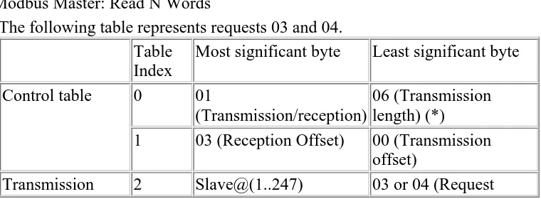
Modbus Master: Read N Words
The following table represents requests 03 and 04.
Table Most significant byte Least significant byte Index
1 03 (Reception Offset) 00 (Transmission offset)
Transmission 2 Slave@(1..247) 03 or 04 (Request
code)
2*N (number of bytes read)
7 First word read
8 Second word read (if N>1) ...
N+6 Word N read (if N>2)
(*) This byte also receives the length of the string transmitted after response
Note: The Rx offset of three will add a byte (value = 0) at the third position in the reception table. This ensures a good positioning of the number of bytes read and of the read words’ values in this table.
Modbus Master: Write Bit
This table represents Request 05.
Table Most significant byte Least significant byte Index
1 00 (Reception offset) 00 (Transmission offset)
5 Slave@(1..247) 05 (Response code)
6 Address of the bit written Reception table
(after response)
7 Value written
(*) This byte also receives the length of the string transmitted after response
Note:
This request does not need the use of offset.
The response frame is the same as the request frame here (in a normal case).
For a bit to write 1, the associated word in the transmission table must contain the value FF00H, and 0 for the bit to write 0.
Modbus Master: Write Word This table represents Request 06.
Table Most significant byte Least significant byte Index
1 00 (Reception offset) 00 (Transmission offset)
5 Slave@(1..247) 06 (Response code)
6 Address of the word written Reception table
(after response)
7 Value written
(*) This byte also receives the length of the string transmitted after response
Note:
This request does not need the use of offset.
The response frame is the same as the request frame here (in a normal case).
Modbus Master: Write of N Bits This table represents Request 15.
Table Most significant byte Least significant byte Index
1 00 (Reception Offset) 07 (Transmission offset) Transmission
where [] means integral part
6 Value of the 1st byte Value of the 2nd byte
7 Value of the 3rd byte Value of the 4th byte
...
(N2/2)+5
(if N2 is even)
Value of the N2th byte
(N2/2+1)+5
The Tx Offset=7 will suppress the 7th byte in the sent frame. This also allows a good correspondence of words’ values in the
transmission table.
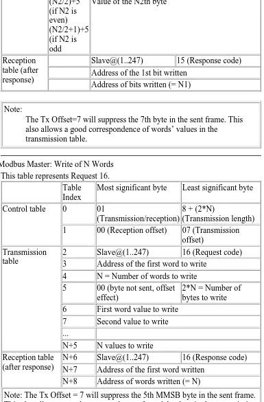
Modbus Master: Write of N Words This table represents Request 16.
Table Most significant byte Least significant byte Index
1 00 (Reception offset) 07 (Transmission offset)
N+6 Slave@(1..247) 16 (Response code) N+7 Address of the first word written
Reception table (after response)
N+8 Address of words written (= N)
Note: The Tx Offset = 7 will suppress the 5th MMSB byte in the sent frame. This also allows a good correspondence of words’ values in the transmission table.
D
LAMPIRAN D
GAMBAR TRENDING PARAMETER PID
PLANT SIMULASI PENGENDALIAN
TEMPERATUR
BAB I
PENDAHULUAN
I.1 Latar Belakang
Perkembangan dalam bidang industri dewasa ini semakin maju. Sebagian
besar bidang industri telah menggunakan teknologi otomasi industri, pengendalian
mesin-mesin industri telah dilakukan dengan menggunakan PLC karena memberi
banyak keuntungan. Keuntungan yang diperoleh dengan menggunakan PLC,
antara lain waktu implementasi proyek lebih cepat, perubahan rancangan dapat
dengan mudah dilakukan, dan perawatannya mudah. Selain itu, pengendalian
mesin-mesin industri dengan menggunakan PLC tidak terbatas pada satu merk
PLC.
Pengendalian menggunakan PLC dapat dilakukan dengan software
SCADA (Supervisory Control and Data Acquisition), yang dapat menampilkan
proses yang sedang berlangsung. Salah satu software SCADA adalah Citect
HMI/SCADA. Dengan menggunakan software Citect HMI/SCADA,
pengendalian dengan menggunakan berbagai merk PLC dapat dilakukan.
I.2 Identifikasi Masalah
Pengendalian proses dengan PLC membutuhkan suatu perancangan yang
menyeluruh. Perancangan yang baik akan memastikan pengembangan suatu
proyek berjalan dengan efisien. Oleh kerena itu, perlu diketahui permasalahan
yang dihadapi. Perancangan di dalam software SCADA juga tidak boleh
diabaikan. Perumusan masalah dalam hal ini adalah “Bagaimana merancang
simulasi tiap plant dengan PLC yang berbeda menggunakan software Citect?”
I.3 Tujuan
Tujuan dari tugas akhir ini adalah mengaplikasikan penggunaan software
Citect HMI/SCADA untuk 2 merk PLC.
BAB I PENDAHULUAN 2
I.4 Pembatasan Masalah
Batasan-batasan masalah pada tugas akhir ini adalah sebagai berikut:
1. Software yang digunakan adalah Citect HMI/SCADA. 2. PLC yang digunakan PLC merk Twido dan Omron.
3. Pengendalian antara Plant simulasi yang satu dan lainnya tidak saling
berhubungan.
4. Komunikasi antar PLC Twido menggunakan protokol modbus.
5. Plant simulasi untuk PLC Omron menggunakan training kit Omron.
I.5 Alat-alat yang Digunakan
Dalam tugas akhir ini yang digunakan adalah:
1. Software yang digunakan adalah Citect HMI/SCADA. 2. PLC yang digunakan PLC merk Twido dan Omron.
3. Komunikasi antara PC dan PLC menggunakan komunikasi serial.
4. Plant yang digunakan adalah plant simulasi pengendalian temperatur dan
pengendalian pencampuran untuk PLC Twido, dan plant simulasi lift
untuk PLC Omron.
I.6 Sistematika Penulisan
• BAB I PENDAHULUAN
Berisi latar belakang, identifikasi masalah, tujuan, pembatasan masalah,
spesifikasi, dan sistematika penulisan. • BAB II LANDASAN TEORI
Berisi tentang dasar PLC, PLC Twido, Twidosoft, PLC Omron,
CX-Programmer, Citect HMI/SCADA, dan PID. • BAB III PERANCANGAN DAN REALISASI
Berisi tentang pemrograman pengendalian proses masing-masing plant,
dan pemrograman software SCADA.
• BAB IV DATA PENGAMATAN
Berisi tentang pembahasan mengenai data pengamatan dan analisis data.
BAB I PENDAHULUAN 3
• BAB V KESIMPULAN DAN SARAN
Berisi tentang kesimpulan dari laporan tugas akhir ini dan saran untuk
pengembangan lebih lanjut.
BAB V
KESIMPULAN DAN SARAN
V.1 Kesimpulan
1. Pengujian software Citect HMI/SCADA untuk pengendalian PLC Twido
dan Omron berhasil, pengalamatan pada software sesuai dengan alamat
pada masing-masing PLC.
2. Waktu respon melalui software Citect pada PLC master Twido untuk start
dan stop plant simulasi pengendalian pencampuran adalah 0,452 dan 0,458
detik, untuk start dan stop plant simulasi pengendalian temperatur adalah
0,454 dan 0,456 detik.
3. Waktu respon yang diberikan oleh software Citect HMI/SCADA untuk
menampilkan indikator lampu pada layar monitor untuk PLC Omron
rata-rata berkisar antara 0,214 sampai 0,22 detik.
4. Parameter PID untuk plant simulasi pengendalian temperatur yang didapat
dari percobaan adalah kp=5000, Ti=500, dan Td=0.
V.2 Saran
1. Program software SCADA pada tugas akhir ini belum memanfaatkan
semua fungsi yang tersedia, seperti fungsi alarm, Cicode, dan diharapkan
untuk pengembangan selanjutnya fungsi-fungsi terebut dapat
dimanfaatkan dan dikembangkan.
2. Diharapkan pada pengembangan selanjutnya, software Citect
HMI/SCADA dapat dibandingkan dengan software SCADA yang lainnya.
DAFTAR PUSTAKA
[1] Asmawan Putra, Aplikasi Jaringan PLC Untuk Pengawasan Beberapa Plant
Menggunakan SCADA Software Vijeo Look, Bandung 2005.
[2] Citect Pty. Ltd, Citect HMI/SCADA Training Manual, Edisi November 2003,
Australia, 2003.
[3] Omron, A Beginner’s Guide to PLC, Edisi Januari 2001, Singapura, 2001.
[4] PLC Training Center, Modul Pelatihan Dasar PLC, Edisi November 2003,
Bandung, 2003.
[5] PLC Training Center, Modul Pelatihan Advance PLC, Edisi November 2005,
Bandung, 2005.
[6] PT. Omron Electronics, PLC Basic Training Manual, Edisi Maret 2004.
[7] PT. Omron Electronics, PLC Advance Training Manual, Edisi Maret 2004.
[8] Schneider Electric, Citect HMI/SCADA Reference Guide, 2003.
[9] www.elektroindonesia.com/elektro/tutor12.html, 4 Februari 2007