THE EVALUATION OF PRECAST
LIGHTWEIGHT FOAM CONCRETE WITH
DIMENSION 1000 x 1000 x 100 cm
(PLFC)
THESIS
By:
ABULGASEM SULIMAN SALEH
BAKOURIS941208013
MASTER PROGRAM IN CIVIL ENGINEERING
UNIVERSITY SEBELAS MARET
SURAKARTA
PRECAST LIGHTWEIGHT FOAM CONCRETE
(PLFC)
VALIDATION
By:
ABULGASEM SULIMAN SALEH
S941208013
Approved by supervisor team:
Position Name Signature Date
SupervisorI Dr. techn. Ir. Sholihin As’ad, MT
NIP. 196710011997021001 ………. ………...
Supervisor II Yusep Muslih P. ST, MT, Ph.D
NIP. 196807021995021001 ………. ………...
Known by:
Head of Study Program Master of Civil Engineering
PRECAST LIGHTWEIGHT FOAM CONCRETE
(PLFC)
By:
ABULGASEM SULIMAN SALEH
S941208013
Has Been Maintained In The Presence of a Team of Examiners Thesis Program of Master in Civil Engineering Study
University Sebelas Maret Surakarta
Supervisor I Dr. techn. Ir. Sholihin As’ad, MT
NIP. 196710011997021001 ...
Supervisor II Yusep Muslih P. ST, MT, Ph.D
NIP. 196807021995021001 ...
Director of the graduate program Head of study program Master of Civil Engineering
Prof. Dr. Ir. Ahmad Yunus, M.S. NIP.196107171986011001
PRONOUNCEMENT
The person who signs here:
NAME : ABULGASEM SULIMAN SALEH NIM : S941208013
Certifies that the thesis entitled:
“PRECAST LIGHTWEIGHT FOAM CONCRETE (PLFC)”
It is really my own work. Anything related to others work is written in quotation, the source of which is listed on the bibliography.
If then, this pronouncement proves wrong, I am ready to accept any academic punishment, including the withdrawal of this thesis and my academic degree.
Surakarta, April 2015
ABULGASEM SULIMAN SALEH BAKOURI S941208013
ACKNOWLEDGEMENT
Praise to Allah SWT the lord of the world, who has given mercy and blessing so that
this thesis with a title PRECAST LIGHTWEIGHT FOAM CONCRETE (PLFC)
can be resolved. This thesis is submitted as a condition for obtaining a master's degree in
Civil Engineering Master Program of Sebelas Maret University.
Respectfully I say many thanks to:
1. Director of Civil Engineering Master Program ofSebelas Maret University. 2. Dr. Ir. Mamok Suprapto, M.Eng, as the head of Civil Engineering Master
Program ofSebelas Maret University.
3. Dr. Eng. Syafi’I, M.T, as secretary of Civil Engineering Master Program of
Sebelas Maret University.
4. Dr. Techn. Ir. Sholihin As’ad. MT, as first supervisor. 5. Yusep Muslih, St., MT., Ph. D., as second supervisor.
6. All faculty staff of Civil Engineering Master Program of Sebelas Maret Universitywho have helped during lectures.
7. My brothers and sisters who always support at every condition.
8. Student colleagues of Civil Engineering Master Program of Sebelas Maret Universitywho gave me inspiration and suggestion.
9. All those who helped me in completing this thesis, the author cannot mention one by one.
I hope this thesis can contribute to the scientific academic community, practitioners in the field of building materials and benefit the wider community in general. The assistance that was given may receive just reward from Allah SWT.
Surakarta, April 2015 Writer,
ABSTRACT
Precast Lightweight Foam Concrete (PLFC) sandwich panel is one of the best
options in building industry. The applications of PLFC mostly are in high rise
building such as flat, school building, apartment and others because the foam
concrete cannot sustain much load such as normal concrete. Due to the concept of
sustainable construction, some manufacturers at the building construction need to
find a new way of achieving the objectives and sandwich panel appear to fulfill their
needed. This thesis is intended to study the precast concrete sandwich wall panel
which is focused on compressive strength capacity, distribution of stress and strain of
window opening panel and observed failure and crack pattern. The material
properties of lightweight foam concrete wall such as compressive strength and
density is also tested.
The dimension of panels was casted as 1000mm×1000mm×100mm and the
opening at the centre with size 375mm×375mm. Experimental results of precast
lightweight foam concrete (PLFC) was compared with computational results and also
previous experiment result.
The test result showed that the density of LFC wall was 1803.8 kg/m3–1873.13 kg/m3and considered as low density or lightweight concrete. Its compressive strength based on cylinder specimen was 15.36 MPa. The panel compressive strength was 26
MPa. The ultimate stress of the panel structure was about 15 MPa then starts the
crack till maximum load of 27.5 MPa before breaking.
Keywords: PLFC, sandwich, panel, density, foam concrete, compressive strength.
ABSTRAK
Precast Ringan Foam Concrete (PLFC) sandwich panel adalah salah satu pilihan terbaik dalam industri bangunan. Aplikasi PLFC sebagian besar berada di gedung bertingkat tinggi seperti flat, gedung sekolah, apartemen dan lain-lain karena beton busa tidak dapat mempertahankan banyak beban seperti beton normal. Karena konsep pembangunan berkelanjutan, beberapa produsen di konstruksi bangunan perlu menemukan cara baru untuk mencapai tujuan dan sandwich panel muncul untuk memenuhi kebutuhan mereka. Tesis ini dimaksudkan mempe;ajari dinding panel sandwich berbahan beton precast yang difokuskan pada kapasitas kuat tekan, distribusi tegangan regangan dari bukaan jendela panel dan pola retaknya. Sifat material dari dinding LFC berupa kuat tekan dan densitas juga diuji.
Dimensi panel dicetak dengan ukuran 1000mm × 1000mm × 100mm dan pembukaan di tengah dengan ukuran 375mm x 375mm. Hasil penelitian dari pracetak beton busa ringan (PLFC) dibandingkan dengan hasil perhitungan dan juga hasil eksperimen sebelumnya.
Hasil pengujian menunjukkan bahwa kepadatan dari dinding LFC adalah 1803.8 kg/m31873.13 kg/m3yang masuk dalam batas beton ringan. Kuat tekan beton ringan adalah 15.36 MPa. Kuat tekan panel beton ringan adalah 26 MPa. Tegangan utama dari struktur panel adalah sekitar 15 MPa kemudian mulai retak sampai beban maksimum 27,5 MPa sebelum runtuh.
CONTENT
1.1 Background of Study ... 1
1.2 Problem Statement ... 2
1.3 Objectives ... 2
1.4 Research Outcomes and significance... 3
CHAPTER II LITERATURE REVIEW AND BASIC THEORY ... 4
2.1 Literature Review... 4
2.1.1 Foam Concrete ... 4
2.1.2 Lightweight Foamed Concrete... 5
2.1.3 Precast Lightweight Foamed Concrete ... 6
2.2 Basic Theory ... 7
2.2.1 Foam Concrete ... 7
2.2.2 Lightweight Foamed Concrete... 9
2.2.3 Precast Lightweight Foamed Concrete ... 11
2.3 Hypothesis... 15
CHAPTER III RESEARCH METHOD ... 16
3.1 Location and Type of Research ... 16
3.2 Research Variables and Parameter... 16
3.2.1 Research Variables... 16
3.2.2 Parameters... 16
3.4.3 Precast Lightweight Foamed Concrete ... 19
3.5 Flowchart ... 21
CHAPTER IV RESULT ANALYSIS AND DISCUSSION ... 22
4.1 Foamed Concrete Materials ... 22
4.1.1 Fine Aggregate Test ... 22
4.1.2 Coarse Aggregate Test ... 23
4.2 Lightweight Foamed Concrete... 25
4.2.1 Lightweight Concrete... 25
4.2.2 Steel Bar... 26
4.3 Precast Lightweight Foamed Concrete ... 26
4.3.1 Density Test ... 26
4.3.2 Compressive strength test ... 28
CHAPTER V CONCLUSION AND SUGGESTION ... 34
5.1 Conclusion ... 34
5.2 Suggestion... 35
LIST OF FIGURE
Figure 2.1 Steel reinforcement bars ... 13
Figure 3.1 Dial gauge on the specimen ... 20
Figure 3.2 Flow chart of research ... 21
Figure 4.1 Fine aggregate gradations ... 23
Figure 4.2 Coarse Aggregate Gradation... 25
Figure 4.3 Density test result of three specimen ... 27
Figure 4.4 Compressive strength for cylinder specimen... 29
Figure 4.5 Compressive strength for cylinder specimen... 30
Figure 4.6 Compressive strength for panel specimen ... 31
Figure 4.7 Stress and strain at dial I... 31
Figure 4.8 Stress and strain at dial II ... 32
Figure 4.9 Stress and strain at dial III ... 33
Figure 4.10 Stress and strain at dial IV ... 33
LIST OF TABLE
Table 3.1 Paramaters ... 16
Table 3.2 Variable ... 16
Table 3.3 Water cement ratio ... 17
Table 4.1 Fine aggregate test result... 22
Table 4.2 Gradation of Fine Aggregate... 22
Table 4.3 Coarse Aggregate Test Result... 23
Table 4.4 Gradation of Coarse Aggregate... 24
Table 4.5 Material requirement for 1m3lightweight concrete. ... 25
Table 4.6 Material requirement for 1 panel and 1 cylinder... 26
Table 4.7 Result of density calculation for each specimen ... 27
Table 4.8 Compressive strength test data of cylinder specimen ... 28
CHAPTER I
INTRODUCTION
1.1 Background of Study
Precast Lightweight Foam Concrete (PLFC) sandwich panel is one of the best options in building industry. There are some advantages of PLFC such low weight, high strength and installable are extremely satisfying the application in construction field that not only can save the construction period, but also the cost, and thus reducing the carrying load of the building. The application of PLFC mostly are in high rise building such as flat, school building, apartment and others and it is specific at the high level such as level 4 or 5 because the foam concrete cannot sustain much load such as normal concrete. However, the usage of this technique will bring up lesser load to the foundation thus can save cost a bit. The PLFC is also widely applied in high rise building or single/multiple story building.
Foamed concrete has a long history and was first patented in 1923, mainly for use as an insulation material. Although there is evidence that the Romans used air entailers to decrease density, this was not really a true foamed concrete. Significant improvements over the past 20 years in production equipment and better quality surfactants (foaming agents) has enabled the use of foamed concrete on a larger scale. Lightweight concrete or foamed concrete is a versatile material which consists primarily of a cement based mortar mixed with at least 20% of volume air. This material is now being used in an increasing number of applications, ranging from one step house casting to low density void fills.
This precast concrete sandwich wall panels will be referred as thesis. Sandwich panels are similar to other precast concrete members such way to design, detailing, manufacturing, handling, shipping and erection; however, because of the presence of an intervening layer of insulation, they have exhibit some unique characteristics and behavior. Where sandwich panel design and manufacturing parallels other precast products (in particular, solid wall panels).
Due to the concept of sustainable construction, some manufacturers at the building construction need to find a new way of achieving the objectives and sandwich panel appear to fulfill their needed. In addition, contractors have found that the use of sandwich panels allows their project site to be quickly “dried in,” allowing other trades to work in a clean and comfortable environment (Kinniburgh et al, 1978).
1.2 Problem Statement
As a result of enhanced population growth and movement of people from rural to urban areas, has to look for alternatives construction method to provide quick and low-cost quality housing. Attempts have been taken to proceed from the traditional building construction technique to a more modern construction method to meet these demands. As a part of these attempts, an additional investigation to develop a PLFC sandwich panel with window opening as a load bearing wall system is undertaken. The problems are formulated below:
1. How is the strength of precast lightweight foamed concrete (PLFC) with steel bar diameter of 6 mm.
2. How is the density and strength of precast lightweight foamed concrete (PLFC) based on cylinder specimen.
3. How is the effect of foam on the mechanical properties of precast lightweight foamed concrete (PLFC).
1.3 Objectives
The aim of this study is to construct a load-bearing Precast Lightweight Foamed Concrete Sandwich Panel (PLFP) with window opening as a structural component for a low rise building construction. In order to achieve this aim, several objectives are set out:
2. To know the density and strength of precast lightweight foamed concrete (PLFC) based on cylinder specimen.
3. To analyze the effect of foam on the mechanical properties of precast lightweight foamed concrete (PLFC).
1.4 Research Outcomes and significance
The significance of this study is to provide useful input into the issue of Precast Lightweight Foamed Concrete panel. From the research and testing is expected to produce a product that is beneficial as following implications:
1. Theoretical Benefits
Optimize the use of foam on foamed concrete especially in the term of Precast Lightweight Foamed Concrete (PFLC).
2. Practical Benefits
CHAPTER II
LITERATURE REVIEW AND BASIC THEORY
This chapter states about the background of topics related to this research. The products of precast lightweight foam concrete sandwich panel (PLFP) come up from the combining of precast foam concrete and precast sandwich panels. Some explanations about precast foam concrete, and precast sandwich panel will be presented in this chapter due to the existing research that has been made before.
2.1 Literature Review
2.1.1 Foam Concrete
Foamed concrete can be considered relatively homogeneous when compared to normal concrete, as it does not contain coarse aggregate phase. However, the properties of foamed concrete depend on the microstructure and composition, which are influenced by the type of binder used, methods of pre-foamation and curing. Though, it has been widely recognized as an insulation material, a renewed interest is shown by researchers in its structural character exhibits. The important application of foamed concrete includes structural elements, non structural partitions and thermal insulating materials. Manufacturers developed foam concretes of different densities to suit the above requirements. The density of foam concrete ranges from 300-1800 kg/m3 and these products were used in trench reinstatement, bridge abutment, void filling, roof insulation, road subbase, wall construction, tunneling etc (Puttappa, 2008).
or ready mixed concrete truck. Second, a synthetic- or protein-based foam-producing admixture can be mixed with the other mix constituents in a high shear mixer. In both methods, the foam must be stable during mixing, transporting and placing (Samsuddin et al, 2013).
Zulkarnain and Ramli investigated the performance of the properties of foamed concrete in replacing volumes of cement at around 10 and 15% by weight. A control unit of foamed concrete mixture made with Ordinary Portland Cement (OPC) and 10 and 15% silica fume (SF) was prepared. SF is commonly used to increase the compressive strength of concrete materials and for economic concerns. The foamed concrete in this study was cured at a relative humidity of 70% and ± temperature of 28°C. This study highlighted the compressive strength of concrete under sealed condition, showing no significant reduction in strength. There was little difference in the performance of the sample compared with that of the usual mixture of concrete. An effective water/cement (w/c) ratio was developed to predict the strength (up to 28 days) of foamed concrete made with normal densities and with a different percentage of SF. The calculated results compared well with the experimental results (Zulkarnaen et al, 2011).
Foamed concrete is either cement paste or mortar classified as lightweight concrete, where air-voids are entrapped in mortar by a suitable foaming agent. It possesses high flow ability, low self-weight, minimal consumption of aggregate, controlled low strength, and excellent thermal insulation properties. A wide range of densities (1600-400 kg/m3) of foamed concrete, with proper control in the dosage of the foam, can be obtained for application to structural, partition, insulation, and filling grades (Ramamurthy et al, 2009).
2.1.2 Lightweight Foamed Concrete
Lightweight concrete can be defined as a type of concrete which includes an expanding agent in that it increases the volume of the mixture while giving additional qualities such as self compacting and lighter weight. Foam concrete is one of the lightweight concrete and was classified as cellular concrete. It has a uniform distribution of air voids throughout the paste or mortar, while no-fines concrete or lightly compacted concretes also contain large, irregular voids (Suryani et al, 2012).
Lightweight foamed concrete is suitable for both precast and cast-in-place applications. Good strength characteristics with reduced weight make lightweight foamed concrete suitable for structural and semi-structural applications such as lightweight partitions, wall and floor panels and lightweight blocks concrete. This structure has become more popular in recent years because its offer more advantages compare to the conventional concrete. Modern technology and a better understanding of the concrete have also helped much in the promotion of the lightweight foam concrete (Samsuddin et al, 2013).
The potential of using lightweight foamed concrete (LFC) in composite load-bearing wall panels in low-rise construction is investigated. From the experimental verification, as expected the mechanical properties of LFC were reasonably low when compared to normal strength concrete. Nonetheless there was a potential of using LFC as fire resistant partition or as load-bearing walls in low-rise residential construction. The objectives of this feasibility is two-fold; to investigate the fire resistance performance of LFC panels of different densities when exposed to fire on one side for different fire resistance ratings based on insulation requirement and to examine whether the composite walling system had sufficient load carrying capacity, based on compression resistance at ambient temperature. Failure of the composite walling was instigated by outward local buckling of the steel sheeting which was followed by concrete crushing of the LFC core. LFC was able to provide sufficient support to prevent the steel sheeting from inward buckling. The results of a feasibility study on structural performance of composite panel system has confirmed it would be possible to design LFC based composite walling system to resist typical floor loads in low rise residential construction (Mydin, 2011).
2.1.3 Precast Lightweight Foamed Concrete
concrete. This new precast system is lighter but higher in strength to weight ratio (Benayoune et al, 2008).
Precast concrete can be defined as a concrete member that is cast and cured at a location other than its actual location. The precast wall panel is part of the precast concrete structure that purposely constructed to speed up the wall making construction and to reduce the dependencies of the skilled worker as well as to reduce the construction waste and cost.Precast concretes and which panels are layered structural systems composed of a low-density core material bonded to,
and acting integrally with, relatively thin, high strength facing materials. The insulated shell
reduces heating and cooling cost (Samsuddin et al, 2013).
The development of foamed concrete and cellular lightweight concrete in Singapura is described. This technology is extremely useful for the developing countries in special areas of construction such as residential and other non-commercial construction. Foam concrete and cellular lightweight concrete can be used for cast in place construction as well as precast construction. Cement based units such as block and tilt up panels can be prefabricated, and this assures a higher level of quality assurance for the constructed facilities (Haq and Liew, 2007).
Among the advantages in using the lightweight materials is it helps to reduce the self weight of the panel and overall cost of the construction. Foamed concrete is one type of cellular lightweight concrete which has been used in the lightweight PCSP especially as the core layer due to its good insulation. However, when it is used as a core, the cost will relatively get higher since the thickness of the core is usually greater than the thickness of the concrete in atypical sandwich panel (Rice et al, 2006).
According to previous study of precast lightweight foamed concrete (PLFC), the present study would like to investigate the mechanical properties of precast lightweight foamed concrete with dimension of 1000 x 1000 x 100 cm.
2.2 Basic Theory
2.2.1 Foam Concrete
applications. It is typically a self-leveling and compacting material that is more resistant to cracking and shrinkage than standard concrete mixes.
The strength and durability of foam concrete varies depending on the components mixed into it. For example, foam concrete made with sand is stronger and has a higher density than foam concrete made with just concrete and foam. Some foam concrete mixes include Portland cement that is mixed with the cement and foam by itself or mixed with pulverized fly ash. It may also include limestone. Each of these mixtures makes a cement product ideal for different applications, but typically all foam concrete products become more resistant when compressed and are not vulnerable to liquefaction or settlement once hardened.
Foamed concrete has been defined as a cementations material, with a minimum of 20% (per volume) foam entrained into the plastic mortar. Foamed concrete is produced by entrapping numerous small bubbles of air in cement paste or mortar. Mechanical foaming can take place in two principal ways:
- By pre-foaming a suitable foaming agent with water and then combining the foam with the paste or mortar.
- By adding a quantity of foaming agent to the slurry and whisking the mixture into a stable mass with the required density.
The most commonly used foam concentrates are based on protein hydrolyzates or synthetic surfactants. They are formulated to produce air bubbles that are stable and able to resist the physical and chemical forces imposed during mixing, placing and hardening. It is standard practice to classify foamed concrete according to the dry density thereof. This density is determined from oven-dried specimens and the actual density of foamed concrete would usually be higher than this density as there would generally be evaporable water present in foamed concrete. The presence of water in foamed concrete elements also results in an increase in thermal conductivity.
Historically, foamed concrete has been perceived to be weak and non-durable with high shrinkage characteristics. Unstable foams have in the past resulted in foamed concrete having properties unsuitable for reinforced, structural applications. Unprotected reinforcement in aerated concrete in which the voids are interconnected would be vulnerable to corrosion even when the external attack is not very severe.
2.2.2 Lightweight Foamed Concrete
Presently the construction industry has shown significant interest in the use of lightweight foamed concrete (LFC) as a building material due to its many favorable characteristics such as lighter weight, easy to fabricate, durable and cost effective. LFC is a material consisting of Portland cement paste or cement filler matrix (mortar) with a homogeneous pore structure created by introducing air in the form of small bubbles. With a proper control in dosage of foam and methods of production, a wide range of densities (400 –1600 kg/m3) of LFC can be produced thus providing flexibility for application such as structural elements, partition, insulating materials and filling grades.
Lightweight concrete is a versatile material which consists primarily of a cement based mortar mixed with at least 20% of volume air. LFC is a cementations material having a minimum of 20 % by volume of mechanically entrained foam in the mortar slurry in which air-pores are entrapped in the matrix by means of a suitable foaming agent. The air-pores are initiated by agitating air with a foaming agent diluted with water; the foam then carefully mixes together with the cement slurry to form LFC. The material is now being used in an ever increasing number of applications, ranging from one step house casting to low density void fills.
Lightweight and free flowing, it is a material suitable for a wide range of purposes such as, but not limited to, panels and block production, floor and roof screeds, wall casting, complete house casting, sound barrier walls, floating homes, void infill, slope protection, outdoor furniture and many more applications. Mix design used due to material that required for 1m3concrete:
Not everyone knows that density and compressive strength can be controlled. In the light weight concrete this is done by introducing air through the proprietary foam process which enables one to control density and strength precisely. To calculate the compressive strength of concrete can use the formula below:
Where: 1,700, 1,600 down to 300 kg/m3. Compressive strengths range from up to 40 MPa down to almost zero for the really low densities. Generally it has more than excellent thermal and sound insulating properties, a good fire rating, is non combustible and features cost savings through construction speed and ease of handling.
2.2.3 Precast Lightweight Foamed Concrete
Precast concrete construction is a method of prefabricating concrete in discrete elements and erecting and incorporating them by crane into their final position in the building structure.
The concept of precast (also known as “prefabricated”) construction includes those buildings
where the majority of structural components are standardized and produced in plants in a location away from the building, and then transported to the site for assembly. These components are manufactured by industrial methods based on mass production in order to build a large number of buildings in a short time at low cost. In general, precast building systems are more economical when compared to conventional multifamily residential construction (apartment buildings) in many countries.
A sandwich panel is a special class of composite materials that is fabricated by attaching two thin but stiff skins to a lightweight but thick core. The core material is normally low strength material, but its higher thickness provides the sandwich composite with high bending, stiffness with overall low density.
The strength of the composite material is dependent largely on two factors:
the material. The shear forces result in the bottom skin in tension and the top skin in compression. The core material spaces these two skins apart. The thicker the core material the stronger the composite. This principle works in much the same way as an I-beam does.
2. The interface between the core and the skin: Because the shear stresses in the composite material change rapidly between the core and the skin, the adhesive layer also sees some degree of shear force. If the adhesive bond between the two layers is too weak, the most probable result will be delaminating.
Reinforced concrete was designed on the principle that steel and concrete act together in resisting force. Concrete is strong in compression but weak in tension. The tensile strength is generally rated about 10 percent of the compression strength. For this reason, concrete works well for columns and posts that are compression members in a structure. But, when it is used for tension members, such as beams, girders, foundation walls, or floors, concrete must be reinforced to attain the necessary tension strength.
Steel is the best material for reinforcing concrete because the properties of expansion for both steel and concrete are considered being approximately the same; that is, under normal conditions, they will expand and contract at an almost equal rate. Another reason steel works well as a reinforcement for concrete is because it bonds well with concrete. This bond strength is proportional to the contact surface of the steel to the concrete. In other words, the greater the surface of steel exposed to the adherence of concrete, the stronger the bond. To calculate the number of steel that used for concrete can use the formula below:
the steel, the better it adheres to concrete. Thus steel with a light, firm layer of rust is superior to clean steel; however, steel with loose or scaly rust is inferior. Loose or scaly rust can be removed from the steel by rubbing the steel with burlap or similar material. This action leaves only the firm layer of rust on the steel to adhere to the concrete. Where as in this study case, steel reinforcement provided the majority compressive strength to the panel during the foam concrete is low density and low strength (McCarthy, 2005). Figure 2.1 shows the steel reinforcement bar for panel system.
Figure 2.1 Steel reinforcement bars
A wall system can be comprised of flat or curved panels (solid, hollow-core, or insulated), window or mullion panels, ribbed panels, or a double-tee. Each type of panel will readily accommodate openings for doors and windows.
The following is a sampling of the numerous products that utilize precast concrete:
a. Building and site amenities
Precast concrete building components and site amenities are used architecturally as
fireplace mantels, cladding, trim products, accessories, and curtain walls. Structural
applications of precast concrete include foundations, beams, floors, walls, and other
structural components. It is essential that each structural component be designed and
b. Retaining walls
Precast concrete provides the manufacturers with the ability to produce a wide range
of engineered earth retaining systems. Products include: commercial retaining
wall, residential retaining walls, sea walls, mechanically stabilized earth (MSE)
panels, modular block systems, segmental retaining walls, etc. Retaining walls have 5
different types which include: gravity retaining wall, semi gravity retaining wall,
cantilever retaining wall, counter fort retaining wall, and buttress retaining wall.
c. Hazardous Materials containment
Storage of hazardous material, whether short-term or long-term, is an increasingly
important environmental issue, calling for containers that not only seal in the
materials, but are strong enough to stand up to natural disasters or terrorist attacks.
d. Sandwich wall
Precast concrete sandwich wall panels have been used on virtually every type of
building, including schools, office buildings, apartment buildings, townhouses,
condominiums, hotels, motels, dormitories, and single-family homes.
Although typically considered part of a building's enclosure, they can be designed to
additionally serve as part of the building's structural system, eliminating the need for
beams and columns on the building perimeter. Besides their energy efficiency and
aesthetic versatility, they also provide excellent noise attenuation, outstanding
durability (resistant to rot, mold, etc.), and rapid construction.
2.3 Hypothesis
H0 = the presence of foam will not improve the mechanical properties of precast
foam concrete.
H1 = the presence of foam will not improve the mechanical properties of precast
CHAPTER III
RESEARCH METHOD
3.1 Location and Type of Research
The research was carried out at Civil Engineering Laboratory of Sebelas Maret University. The method was used in this study is an empirical design method experimentally by conducted experiment to obtain the data. The data was processed to obtain comparison of the result of each asphalt types.
The main objective of this chapter is to describe the experimental work. In this project, the experimental investigation will be carried out. The procedure of research can mainly divide into two. The first part is the materials preparation and the second part is the laboratory testing. A window opening precast lightweight foam concrete sandwich panel will be tested until failure under axial loading.
3.2 Research Variables and Parameter
3.2.1 Research Variables
i. Dependent variable, strength of lightweight foam concrete.
ii. Independent variable, foam content in the mix design and number of steel bar.
3.2.2 Parameters
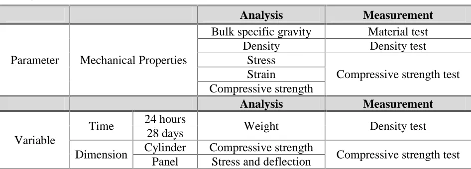
The parameter that was used in this study is shown in Table 3.1. Table 3.1 Parameter
Time 24 hours Weight Density test 28 days
3.3 Data and Material
Data source available sometimes was become a problem when the research will be conducted. Experimental method was chosen to obtain the data that was conducted in the Civil Engineering Laboratory. The data used in this study include primary data and secondary data. Primary data is data collected through a series of experiments conducted directly. The primary data are as follow:
1. Density test
2. Compressive strength test 3. Tensile test
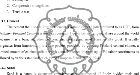
3.3.1 Cement
The cement that used is Portland cement. Portland cement (often referred to as OPC, from
Ordinary Portland Cement) is the most common type of cement in general use around the world
because it is a basic ingredient of concrete, mortar, and most non-specialty grout. It usually originates from limestone. It is a fine powder produced by grinding Portland cement clinker, a limited amount of calcium sulfate which controls the set time and up to 5% minor constituents as allowed by various standards such as the European Standard EN197-1.
3.3.2 Sand
Sand is a naturally occurring granular material composed of finely divided rock and mineral particles. The composition of sand is highly variable, depending on the local rock sources and conditions, but the most common constituent of sand in inland continental settings and non-tropical coastal settings is silica (silicon dioxide, or SiO2), usually in the form of quartz.
3.3.3 Water/cement ratio
In this study of precast lightweight foamed concrete, the ratio of materials used in mix design for sand, cement, foam and water based on ATS 10 (Foamed concrete/ low density fill) are presented at Table 3.3.
Coarse agg : cement 3:1
3.3.4 Steel Reinforcement bar
A rebar (short for reinforcing bar), also known as reinforcing steel, reinforcement steel, rerod, or a deformed bar, is a common steel bar, and is commonly used as a tensioning device in reinforced concrete and reinforced masonry structures holding the concrete in compression. It is usually formed from carbon steel, and is given ridges for better mechanical anchoring into the concrete (window opening reinforced bar can be seen at appendix B p.6).
3.3.5 Foam
The foam was produced by a foam generator in which a foam concentrate diluted in water was combined with compressed air. The ratio of foam concrete to water used was one part of foam concentrate to 5 to 40 parts of water. In this process, foam concentrate (synthetic foam agent) which based on protein hydrolyzates were used. The foam is formulated to produce air bubbles that are stable and able to resist the physical and chemical forces imposed during mixing, placing and hardening of the concrete. The mixture was then forced through a restriction to be discharged directly into the mixer.
A foaming agent is chemical compounds which facilitates the formation of foam or helps foam maintain its integrity by strengthening individual foam bubbles. Foaming agents are used in many industrial processes, and also around the home. In fact, chances are high that you came into contact with a foaming agent at some point today, perhaps while washing the dishes, preparing a load of laundry, or washing your hair.
A broad spectrum of chemicals can act as foaming agents. In all cases, they act as surfactants, reducing surface tension. Foaming agents are often packaged with products which are supposed to foam, such as detergent, activating when the detergent is released to promote the formation of foam and to keep the foam together. It is also possible to add such agents to materials while they are being processed, as seen when metal foams are produced in metalworking applications.
The steps of making foamed concrete mixture (foam preparation can be seen at appendix B p.3):
4. Turn on the foam generator and adjust the foam viscosity then pour into mixer. Mix the entire component in the mixer until get the appropriate mixture.
3.4 Analysis
3.4.1 Foam Concrete
The first step of this research is survey the literature to find references that has relevance to the topic of research especially in the foam concrete. The study comparison has aim to find the comparison of PLFC in the previous research. The dimension of panels will be cast as 1000mm×1000mm×100mm and the opening at the centre with size 375mm×375mm. The effect of load will be consider to lateral deflection, position of critical deflection, ultimate failure load, first crack, effect of slenderness ratio to strength and failure mechanism of precast foam concrete sandwich panels will be concluded.
3.4.2 Lightweight Foamed Concrete
The analysis of density is used to determine the concrete specimen includes or meet the characteristic of lightweight concrete. The range of lightweight concrete has been mentioned and has standard value.
3.4.3 Precast Lightweight Foamed Concrete
Compressive strength test is used to analyze the strength of PLFC. The compressive strength of the concrete was obtained using the procedures in ASTM C39. The specimen were tested in a Forney compression testing machine. Neoprene caps set in metal plates were used to provide an even loading surface. The load was applied at a rate between 5000 kN. The concrete load failure was recorded. The compressive strength was indicated by specimen load at failure divided by specimen area cross section.
The step of casting the panel was conducted at Civil Engineering Laboratory of Sebelas Maret University are described below:
1. The main reinforcement bar was cut into pieces for length about 1000mm for the full panel and 280mm at the window opening.
2. The rebar was tied up by using small wire according to the mould that has been set up. 3. The shear connector was tied up with the reinforcement bar.
5. The surface of the bottom layer was brush on with some oil. The function is for the panel easier to put out from the formwork after the drying process has been completed
6. The foam concrete mixing was poured into the formwork for the first layer 7. Then the second layer of foam concrete mix was poured into that formwork. 8. Do the finishing of the surface of the panel.
9. Finish the PLFP section.
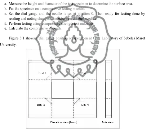
Steps of compressive strength for cylinder testing are as follows:
a. Measure the height and diameter of the test specimen to determine the surface area. b. Put the specimen on a compressive testing machine
c. Set the dial gauge and the needle is set at position 0. Then ready for testing done by reading and noting changes in numbers on the dial needles.
d. Perform testing using compressive strength test machine. e. Calculate the compressive strength.
Figure 3.1 shows a dial gauge position on specimen at Civil Laboratory of Sebelas Maret University.
Figure 3.1 Dial gauge on the specimen
Dial 1 Dial 2
Dial 3 Dial 4
3.5 Flowchart
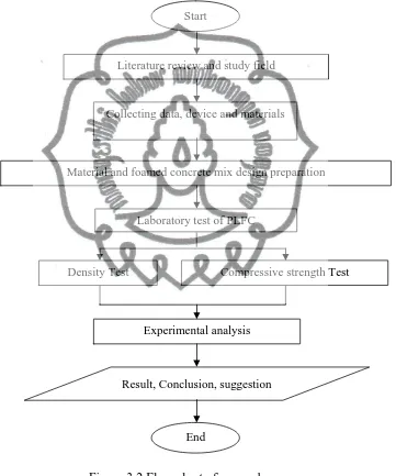
The aim of the project can be achieved by the following sequence of steps shown in Figure 3.2. The first step from the sequence is identification of the problem statement. Then identify objectives and scope of work. After that, the research will specific on the critical review of study on sandwich panel with windows opening. However, due to the limitation of the experimental work and it`s test setup, a half scale model of the panel will be constructed.
Figure 3.2 Flow chart of research
Start
Literature review and study field
Collecting data, device and materials
Material and foamed concrete mix design preparation
Laboratory test of PLFC
Experimental analysis
Result, Conclusion, suggestion
End
CHAPTER IV
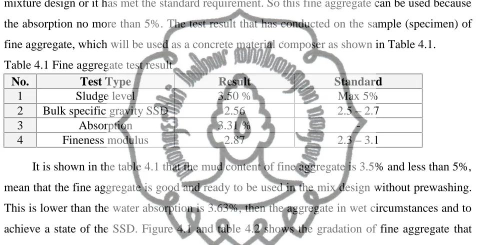
mixture design or it has met the standard requirement. So this fine aggregate can be used because the absorption no more than 5%. The test result that has conducted on the sample (specimen) of fine aggregate, which will be used as a concrete material composer as shown in Table 4.1.Table 4.1 Fine aggregate test result
No. Test Type Result Standard
1 Sludge level 3.50 % Max 5% 2 Bulk specific gravity SSD 2.56 2.5–2.7
3 Absorption 3.31 %
-4 Fineness modulus 2.87 2.3–3.1
It is shown in the table 4.1 that the mud content of fine aggregate is 3.5% and less than 5%, mean that the fine aggregate is good and ready to be used in the mix design without prewashing. This is lower than the water absorption is 3.63%, then the aggregate in wet circumstances and to achieve a state of the SSD. Figure 4.1 and table 4.2 shows the gradation of fine aggregate that has meet the standard requirement for mixture and the value is between maximum value and minimum value.
Table 4.2 Gradation of Fine Aggregate
Sieve Size
(mm)
Blocked Passing
Cumulative (%) Standard Weight (gr) Percentage (%) Cumulative (%)
9.5 0 0 0 100 100
4.75 101 3.37 3.37 96.63 95-100
2.36 321 10.72 14.09 85.91 80-100
1.18 500 16.70 30.79 69.21 50-85
0.85 675 22.55 53.34 46.66 25-60
0.3 1089 36.37 89.71 10.29 10-30
Total 2994 100 387.21
Figure 4.1 Fine aggregate gradations
4.1.2 Coarse Aggregate Test
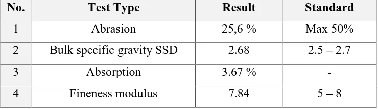
From the test result found that fine aggregate water absorption is 3.67%, whereas the maximum limit is 5%, its mean that this fine aggregate has been good enough for concrete mixture design or it has met the standard requirement. This shows aggregate ability to absorb water in a state of absolute dry until dry saturated at 3.67% of the dry weight of the aggregate itself. So this fine aggregate can be used because the absorption no more than 5%. The test result that has conducted on the sample (specimen) of coarse aggregate, which will be used as a concrete material composer as shown in Table 4.3.
Table 4.3 Coarse Aggregate Test Result
No. Test Type Result Standard
1 Abrasion 25,6 % Max 50% 2 Bulk specific gravity SSD 2.68 2.5–2.7
3 Absorption 3.67 %
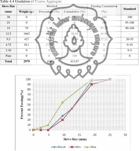
This abrasion test of concrete in the laboratory is to obtain concrete abrasion coefficient. The test result value is the value of the concrete surface resistance of a building component of water that can be used as a comparison with the value of the coefficient of abrasion on the building due to abrasion flow that transports sediment. The test result is 25.6% and the limit is 50% that is mean this already meet the standard condition. Figure 4.2 and table 4.4 shows the gradation of coarse aggregate has meet the standard requirement for mixture and the value is between maximum value and minimum value.
Table 4.4 Gradation of Coarse Aggregate
Sieve Size
(mm)
Blocked Passing Cumulative
(%) Standard
Weight (gr) Percentage (%) Cumulative (%)
38 0 0 0 100 100
25 0 0 0 100 95-100
19 79 2.65 2.65 97.35 90-100
12.5 1662 55.79 58.44 41.56
-9.5 427 14.33 72.78 27.22 20-55
4.75 811 27.22 100 0 0-10
2.36 0 0 100 0 0-5
Pain 0 0 100 0 0
Figure 4.2 Coarse Aggregate Gradation
4.2 Lightweight Foamed Concrete
4.2.1 Lightweight Concrete
The concrete mix design calculations performed by the trial mix method. Water-cement ratio used was 0.55 with a plan of lightweight foam concrete compressive strength of ≥ 15 MPa
and density ranges between 1800 kg/m3 - 1900 kg/m3. The material that required for 1m3 concrete (equation 1):
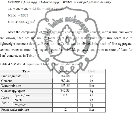
After the composition of fine aggregate, coarse aggregate, cement, mortar mix and water are known, then see the use of foam agent table and water mixture to mix foam due to lightweight concrete density. Based on the Table, can be obtained the need of fine aggregate, cement, water mixture, foam agent (spectafoam, HDM, polymer) and water mixture of foam for 1 m3concrete as in Table 4.5.
Table 4.5 Material requirement for 1m3lightweight concrete.
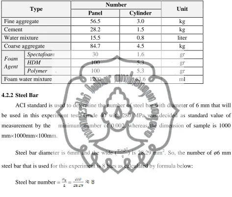
Table 4.6 Material requirement for 1 panel and 1 cylinder
Foam water mixture 1200 63.6 ml
4.2.2 Steel Bar
ACI standard is used to determine the number of steel bar with diameter of 6 mm that will be used in this experiment test. Grade 40 with 280 MPa was decided as standard value of
measurement by the ρ minimum number of 0.002, whereas the dimension of sample is 1000
mm×1000mm×100mm.
Steel bar diameter is 6mm and the wide ( ) is 28.29 mm2. So, the number of ø6 mm steel bar that is used for this experiment is 8 bars as calculated by formula below:
Steel bar number = =
4.3 Precast Lightweight Foamed Concrete
4.3.1 Density Test
Density =
concrete weight (W) = 9.1 kg
concrete volume (V) = 0.0050449 m3 Table 4.7 Result of density calculation for each specimen
Sample Weight after 24
Figure 4.3 shows the result of density test of 3 concrete cylinder specimens with 15 cm of diameter and 30 cm of height.
Figure 4.3 Density test result of three specimen
Based on the density test results obtained that density range of 1803.8 kg/m3up to 1873.13
lightweight concrete is concrete containing lightweight aggregate and has density value of 1900 kg/m3. With its low density, this concrete imposes little vertical stress on the substructure, a particularly important issue in areas sensitive to settlement.
4.3.2 Compressive strength test
In this test there are two types of specimen that is tested (cylinder and panel) which every types has three samples (Cylinder specimen can be seen at appendix B p.8). The presence of foam in the mixture will influence the properties of concrete. Maximum load is used to determine the compressive strength of concrete by formula as follow:
As example of calculation will be given from specimen 1 for cylinderspecimen. Pmax = 260000 N
A = 0,25 x π x1502 = 17671,5mm2
So the compressive strength of specimen is:
f’c =
17671,5 260000
= 14,72MPa.
The results of the compressive strength test of cylinder can be seen in Table 4.8 and Figure 4.4.
Table 4.8 Compressive strength test data of cylinder specimen
Figure 4.4 Compressive strength for cylinder specimen
Figure 4.5 Compressive strength for cylinder specimen
The density of specimen and comparison sample was not different, which the specimen has density of 1833 kg/m3 and 1843 kg/m3 for comparison sample. Concrete density influences the mechanical properties due to the production of pores. The pores produced with each density differ in term of amount and size of pores. More pore and voids were produced with low density of concrete as more foam was added into the mix. Lower density of concrete indicates larger porosity value or greater amount of air contained (larger pore size). The pores merge with each other thus creating large size of pores. This will lead to weak cell structure between pores and matrix as there was insufficient surface area that connects the pore and matrix. As a result, the compressive strength of concrete was also reduced. Whereas in this study, the specimen with coarse aggregate (lower density) resulted higher compressive strength than comparison sample without coarse aggregate (higher density) that probably reduce the pores in structure.
The presence of coarse aggregate was increased the strength that probably caused by the additional water required for taking into account the water absorption of the aggregates. Higher strength may be due to the accumulation of un-hydrated cement particles during mixing, which continuously hydrate and contribute strength to the aggregate.
From the research that was conducted obtained the compressive strength concrete value of 15.36 MPa for cylinder. This result shows that the specimen of cylinder has higher compressive strength then previous research that performed by Andi (2014) with result of 14.15 MPa. The presence of coarse aggregate in this experiment influence the bonding between material and reduce the porosity on concrete. Table 4.9 is presented the compressive strength test result of PLFC specimen.
Figure 4.6 present the compressive strength test graph of 3 PLFC specimens.
Figure 4.6 Compressive strength for panel specimen
The Figure 4.6 shows the result of compressive strength test for panel specimens of 26 MPa. Specimen 1 has higher result than others two specimen, which this condition occurred because of the differences foam mixing of 1 minute, 2 minutes and 3 minutes respectively. The time mixing of foam will influence the properties of concrete as resulted at specimen I which has lower compressive strength (Panel specimen test can be seen at appendix B p.9).
Figure 4.7 shows the result of stress and strain on the panel from dial measurement (data result can be seen at appendix A p.2).
Figure 4.7 Stress and deflection at dial I
Lo
ad
(M
Pa)
Figure 4.7 shows the stress and deflection on the specimen at dial I. The value of maximum load (Pmax) and specimen deflection (mm) was measured. The maximum load was
27.5 kN, whereas for deflection at dial I was 1.0443 mm. Figure 4.8 shows the result of stress and strain on the panel from dial measurement (data result can be seen at appendix A p.2).
Figure 4.8 Stress and deflection at dial II
Figure 4.8 shows the stress and deflection on the specimen at dial II. The value of maximum load (Pmax) and specimen deflection (mm) was measured. The maximum load was
27.5 kN, whereas for deflection at dial II was 0.8883 mm. Figure 4.9 shows the result of stress and strain on the panel from dial measurement (data result can be seen at appendix A p.2).
Figure 4.9 Stress and strain at dial III
Figure 4.9 shows the stress and deflection on the specimen at dial III. The value of maximum load (Pmax) and specimen deflection (mm) was measured. The maximum load was
27.5 kN, whereas for deflection at dial III was 0.9134 mm. Figure 4.10 shows the result of stress and strain on the panel from dial measurement (data result can be seen at appendix A p.2).
Figure 4.10 Stress and deflection at dial IV
From the Figure 4.7, Figure 4.8, Figure 4.9 and Figure 4.10 shows the stress strain distribution across the surface of panel. The ultimate stress of the panel structure was about 15 MPa then starts the crack till maximum load of 27.5 MPa before breaking. The strain occurred at dial I was greater than others dial, it indicates that the ability of panel to resist the load was not similar at each dials. The ability to stand over or resist the crack can be seen by the strain distribution of panel surface. The panel structure at dial I have better condition in the term of strain that can keep the form of panel before breaking.
Lo
ad
(M
Pa
)
CHAPTER V
CONCLUSION AND SUGGESTION
5.1 Conclusion
From the test results, analysis of data and discussion of research can be concluded as follow:
1. The manufacturing of PLFC with steel bar diameter of 6 mm has maximum compressive strength of 27.5 MPa. Panel PLFC 3 recorded a higher degree of strength compared to panels PLFC 1 and PLFC 2.
2. Density value of lightweight foam concrete based on cylinder specimen is 1833.56 kg/m3 which is containing of lightweight aggregate as additional material with compressive strength value of 15.36 MPa. Where the normal lightweight foam concrete has average of compressive strength of 14.15 MPa. The panel specimen of lightweight foam concrete has compressive strength value of 27.5 MPa, 25.5 MPa and 25 MPa respectively with the average of 26 MPa. Specimen 3 showed the highest compressive strength value than two others specimen.
5.2 Suggestion
The results from previous research related with sandwich panels bring a lot of benefit to others the sandwich is the usage of materials, manpower and cost decreases were this proves that this material is capable and suitable to be applied in the construction industry. To follow up this study would need to make some corrections so that further research can be better. As for suggestions for further research, include:
1. This project was used one variation of foam agent amount. To obtain more general conclusion, the experiment should use various of foam amount that may produce better properties.
2. Using more types of stell bar dimension that may produce different result. 3. The available of foam mixer device at laboratory to control the foam mixiture.
4. The presence of various mix design in the specimen due to mechanical properties test. 5. Silica fume can be addition material to enrich the various of mix design in order to get
REFERENCE
Arasteh Ali Reza, 1988. Structural application of lightweight aggregate foamed concrete. PhD
theseis, Polytechnic of Central London.
Benayoune A. A, Abdul Samad D. N, Trikha A. A, Abang A, Ellinna S. H. M, Flexural
Behaviour of Pre-Cast Concrete Sandwich Composite Panel-Experimental and Theoritical Investigations, Elsevier, London, UK, 2008.
Haq Mazhar, Liew Alex, 2007, Light Weight/Low Cost Construction Methods For Developing Countries, Journal of CBM-CI International Workshop, Karachi, Pakistan.
Kinniburgh Wiliam, Short Andrew, 1978, Lightweight Concrete, Applied Science Publisher Ltd, London.
McCarthy A, Jones M.R, 2005, Preliminary views on the potential foamed concrete as a structural material, Magazine of Concrete Research, 2005, 57, No. 1, February, 21–31. Mydin Othuman A, 2011, Potential of Using Lightweight Foamed Concrete in Composite
Load-Bearing Wall Panels in Low-rise Construction, Journal of Concrete Research Letters, Vol. 2 (2).
Puttappa Gundenahalli, 2008, Mechanical properties of foamed concrete, Journal of
international conference of construction and building technology, ICCBT.
Ramamurthy K, Nambiar E.K.K, Ranjani G.I, 2009, A classification of studies on properties of foam concrete, Cement and Concrete Composites 31, 388-396.
Rice M. C, Fleischer C. A, Zupan M, 2006, Study on the Collapse Of Pin-Reinforced Foam Sandwich Panel Cores. Journal of Experimental Mechanics, 46, 197-204.
Sach, J. Seifert, H. 1999. Foamed concrete technology: possibilities for thermalInsulation at high temperatures. CFI Forum of Technology, DKG 76, No. 9,pp 23-30.
Samsuddin S, Mohamad N, 2013, Structural Behaviour of Precast Lightweight Foamed Concrete Sandwich Panel Under Axial Load: An Overview, Journal of University Tun Hussein Onn,
Malaysia.
Suryani S, Mohamad N, 2012, Structural Behavior of Precast Lightweight Foamed Concrete Sandwich Panel under Axial Load: An Overview, International Journal of Integrated
Van Dijk S, 1991. Foamed Concrete, July/August 1991, pp. 49-54
Zulkarnain Fahrizal, Ramli Mahyuddin, 2011, Durability of Performance Foamed Concrete Mix Design with Silica Fume for Housing Development, Journal of Materials Science and
TENSILE TEST
Data for Panel I
NO Load Kg Dial Crack Pattern Information
D1
(mm) (mm)D2 (mm)D3 (mm)D4
1 0 0 0 0 0
36 17500 6220 4845 5837 5245 37 18000 6350 4935 5997 5335 38 18500 6400 4980 6130 5380 39 19000 6530 5010 6130 5410 40 19500 6640 5137 6130 5437 41 20000 6720 5155 6130 5455 42 20500 6890 5185 6130 5485 43 21000 6980 5215 6210 5515 44 21500 7080 5237 6220 5537 45 22000 7160 5252 6233 5574 46 22500 7240 5279 6242 5611 47 23000 7350 5193 6260 5648 48 23500 7390 5221 6345 5685 49 24000 7460 5238 6465 5922 50 24500 7530 5347 6530 6059 51 25000 7660 5454 6625 6196 52 25500 7730 5861 6745 6233 53 26000 7880 5953 6830 6360 54 26500 7950 6244 7010 6507 55 27000 8020 6320 7213 6564
56 27500 8080 6484 7525 6684 Ultimate Load 57 27000 8507 6590 7738 6768
58 26500 8630 6576 7807 6520 59 26000 8765 6350 7701 6383 60 25000 8612 6200 7550 6159 61 24000 8407 6000 7365 6047
Data for Panel II
NO Load Kg D1 Dial Crack Pattern Information
(mm) (mm)D2 (mm)D3 (mm)D4
1 0 0 0 0 0
37 18000 7496 5885 7066 6460 38 18500 7555 5897 7082 6495 39 19000 7590 5930 7091 6529 40 19500 7623 5970 7098 6560 41 20000 7680 6059 7110 6561 42 20500 7710 6066 7123 6583 43 21000 7735 6071 7138 6599 44 21500 7764 6080 7150 6616 45 22000 7790 6087 7164 6635 46 22500 7825 6095 7185 6652 47 23000 7848 6105 7192 6667 48 23500 7861 6120 7203 6682 49 24000 7895 6124 7213 6697 50 24500 7915 6130 7225 6715 51 25000 7940 6139 7240 6737
52 25500 7966 6142 7255 6762 Ultimate Load
53 25000 7989 5150 7267 6782 54 24500 7042 4156 7110 6804 55 24000 5031 4162 6293 6821 56 23500 4060 3168 4306 6832
40 19500 7623 5970 7098 6560 41 20000 7680 6059 7110 6561 42 20500 7710 6066 7123 6583 43 21000 7735 6071 7138 6599 44 21500 7764 6080 7150 6616 45 22000 7790 6087 7164 6635 46 22500 7825 6095 7185 6652 47 23000 7848 6105 7192 6667 48 23500 7861 6120 7203 6682 49 24000 7895 6124 7213 6697 50 24500 7915 6130 7225 6715
51 25000 7941 6239 7243 6737 Ultimate 52 24500 7966 6442 7245 6852
53 24000 7989 6650 7267 6882 54 23500 8012 6756 7280 6904 55 23000 8136 6962 7293 6925