2011 International Conference on Electrical Engineering and Informatics
17-19 July 2011, Bandung, Indonesia
Modeling of Wind Energy System with MPPT
Control
Aryuanto Soetedjo
#1, Abraham Lomi
#2, Widodo Puji Mulayanto
#3#
Department of Electrical Engineering, National Institute of Technology (ITN) Malang Jalan Raya Karanglo Km. 2 Malang, Indonesia
1
aryuanto@gmail.com
Abstract— This paper presents the modeling of wind energy systems using MATLAB Simulink. The model considers the MPPT (Maximum Power Point Tracking) technique to track the maximum power that could be extracted from the wind energy, due the non-linear characteristic of the wind turbine. The model consists of wind generation model, converter model (DC-DC converter), and MPPT controller. The main contribution of our work is in the model of DC-DC converter (buck converter) which is developed in rather details, which allows the MPPT controller output (duty cycle) adjusts the voltage input of the converter to track the maximum power point of the wind generator. The simulation results show that the developed model complies with the theoretical one. Further the MPPT control shows a higher power output compared to the system without MPPT.
Keywords— wind turbine, MPPT, buck converter.
I. INTRODUCTION
Nowadays, demands for the renewable energy resources are increase significantly. The most popular ones are wind energy and solar energy resources. Both offer advantages such as free and clean. But, the wind energy has a lower installation costs compared to the solar energy [1],[2]. The main problem of wind energy system is that its availability is sporadic, and therefore it should be backed by the other power resources [3].
The wind energy system extracts the wind energy and converts it to the electrical energy. The output power of wind energy system varies depend on the wind speed. Due the non-linear characteristic of the wind turbine, it is a challenging task to maintain the maximum power output of the wind turbine for all wind speed conditions. There are extensive researches concerning with the approaches to track the maximum power point of the wind turbine called as MPPT (Maximum Power Point Tracking) control [1] – [12].
There are three common MPPT methods [13], i.e. : a) perturbation and observation (P&O) or hill climbing searching (HCS) [1],[5],[7],[9],[10]; b) wind speed measurement (WSM) [3],[4],[8],[11]; c) power signal feedback (PSF) [6,7]. In the P&O method, the rotor speed is perturbed by a small step, then the power output is observed to adjust the next perturbation on the rotor speed. In [9], [10], a constant step is introduced in the perturbation process. A variable step is employed in [1] by considering the slope of power changes. In [5], an adaptive memory algorithm is added to increase the
search operation. In [7], an advanced hill-climbing searching is proposed to work with different level of turbine inertia by detecting the inverter output power and inverter dc-link voltage.
In the WSM method, the wind speed and rotor speed are measured and used to determine the optimum tip speed ratio (TSR). In [3], fuzzy logic control is employed to enhance the performance by dealing the parameter insensitivity. This method is simple, but has the drawback as follows [13]: a) It is difficult and expensive to obtain accurate value of wind speed; b) The TSR is dependent on the wind energy system characteristics. In [8], two Artificial Neural Networks (ANN) called ANN’s wind estimation (ANNwind) and ANN’s power
estimation (ANNpe) are adopted to estimate the wind speed
and output power respectively. The estimated wind obtained by ANNwind not only replaces the anemometer but also solves
the problems of aging anemometer and moved position [8]. The PSF method tracks the maximum power by reading the current power output to determine the control mechanism to follow the maximum power curve stored in Lookup-table. In [6], fuzzy logic control is developed to overcome the uncertainties of the power curves. The main drawback of this method is that the maximum power curve should be obtained by simulations or experimental test. Thus it is difficult and expensive to be implemented [7].
Since wind speed varies unpredictable, it is convenient to develop the model to simulate the wind energy systems. Many researches simulate their proposed algorithm using model first before real implementation [2]-[8],[11],[12]. The model usually consists of wind generation model, converter model (DC-DC converter), load/battery model, and controller (MPPT controller) model. In this paper, we develop such models to simulate the MPPT algorithm to track the maximum power of the wind turbine (permanent magnet generator). Our model adopt the wind turbine model proposed by [2], our proposed buck converter model, and MPPT technique using P&O algorithm. The main contribution is in the model of DC-DC converter (buck converter) which is developed in rather details and allows the MPPT controller output (duty cycle) adjusts the ratio of voltage input-output of the converter. More
E2 - 4
precisely, when the duty cycle is changed, the input voltage of the buck converter, i.e. the output voltage of the generator follows the changes appropriately. Therefore the input voltage of the buck converter is considered as the output of the model. There is a lack information in the literature considers this thing.
The organization of the paper is as follows. Section 2 describes the models of wind energy system. Section 3 presents the simulation results. Conclusion is covered in section 4.
II. SYSTEM MODELING
Figure 1 illustrates the configuration of wind energy system. The wind generator consists of a wind turbine coupled with a permanent magnet synchronous generator (PMSG). The rectifier is a three phase diode rectifier for converting three-phase AC voltage to DC voltage. The buck converter is a DC-DC converter that the voltage input-output ratio is controlled by a PWM (Pulse width modulation) signal from the MPPT controller. The MPPT controller read the voltage and current of the wind generator output to determine the PWM signal.
Fig. 1 The configuration of wind energy system
A. Wind Generator Model
Wind energy systems convert the kinetic energy of the wind into the electrical energy. The kinetic energy produced by a moving object is expressed as
2
d is the distance travelled by the wind.
The mechanical power of the wind turbine (Pw) is defined is the kinetic energy over the time (t), thus Pw is expressed as The power expressed by Eq. (3) is the ideal power captured by the wind turbine. The actual power of the wind turbine
depends on the efficiency of the turbine represented by
) the ratio between the turbine speed and the wind speed, and is given by the turbine. Therefore, the actual power captured by the wind turbine is given by
( , ) 3
Then, the torque of the wind turbine could be expressed as [2]
( , ) 2 function and expressed by a generic function [6]
⎟⎟
Figure 2 shows the Cp-λ characteristics for the different values
of β. From the figure, we may observe that for a fixed pitch
When the wind speed changes, the rotor speed and the power captured by the wind turbine will change. According to Eqs. (4), (5), (7), for a certain wind speed, the power will be varied with respect to the rotor speed (ω), and there is a point when the power is maximum, i.e. at the optimal rotor speed (ωopt). Figure 3 illustrates the curves of the wind turbine
speeds. From the figure, it is clear that for the different power curves, the maximum powers are achieved at the different rotor speeds. Therefore, the rotor speed should be operated at the optimum speed. This technique is called as MPPT (Maximum Power Point Tracking) technique as discussed in the next section.
Fig. 3 The wind turbine power curves [13].
In this paper, the permanent magnet synchronous generator (PMSG) is modeled as proposed by [2]. The dynamic model of the generator is given by the following equations:
iq is the quadrature current id is the direct current
L is the inductance of the stator windings Rs is the resistance of the stator windings ωe is the electrical angular speed
φm is the flux linked by the stator windings vs is the line voltage in the PMSG terminals P is the number of poles
J is the inertia of the rotating system Tt is the turbine torque
ωe is the angular rotor speed.
B. MPPT
The most common technique used in the MPPT controller is Perturb and Observe (P&O) technique [1], [10], [13], [16]. This method is based on perturbing the rotor speed in small steps and observing the changes in power. In the PMSG, the output current and voltage are proportional to the torque and rotor speed. Thus perturbing or varying the output voltage of the generator will cause the varying in rotor speed. Perturbing
the voltage could be performed by adjusting the duty cycle (PWM signal) of the buck converter as shown in Fig. 1.
Flowchart of the P&O algorithm is illustrated in Fig. 4. The P&O algorithm operates by varying the duty cycle of the buck converter, thus varying the output voltage of the wind generator, and observe the resulting power to increase or decrease the duty cycle in the next cycle. If the increase of duty cycle produces an increase of the power, then the direction of the perturbation signal (duty cycle) is the same as the previous cycle. Contrary, if the perturbation duty cycle produces a decrease of the power, then the direction of perturbation signal is the opposite from the previous cycle.
Fig. 4 P&O algorithm [16].
C. Buck Converter Model
Buck converter is used to step-down the DC voltage. The basic circuit of the buck converter is shown in Fig. 5. There are four main components: switching power MOSFET S, freewheeling diode D, inductor, and output filter capacitor C. The converter might work in two different modes: a) continuous conduction mode, in which the inductor’s current never zero; b) discontinuous conduction mode, in which the inductor’s current falls to zero during the part of period. In this paper, we only consider the continuous conduction mode.
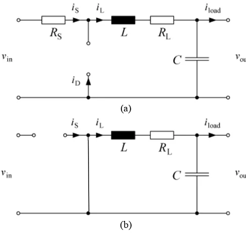
In the continuous conduction mode, the buck converter could be in two different states: ON state and OFF state. Figs. 6(a) and 6(b) show the equivalent circuit in the ON state and OFF state, respectively, where Rs is the ON-resistance of the
MOSFET and RL is the resistance of inductor.
(a)
(b)
Fig. 6 Equivalent circuit in (a) ON state; (b) OFF state [15].
In the ON state, power MOSFET S is ON and diode D is OFF. The system equation is expressed as:
L vin iL RS RL vout system equation is expressed as:
) The average voltage across the inductor in the steady state condition is the summation of Eqs. (13) and (15), yields
out Where d is the period of the ON state. The average current flowing in the capacitor in the steady state condition is the summation of Eqs. (14) and (16), yields
The average input current is given by
is =diL (19)
As described in previous section, the MPPT technique needs to change the output voltage of the wind generator, i.e. the input voltage of the buck converter to track the maximum power point. In the real hardware implementation, this requirement is easily accomplished, due to the input-output relationship of the buck converter. More clearly, when the input voltage of the converter is kept constant, varying the duty cycle will change the output voltage of the converter, and vice versa, when the output voltage of the converter is kept constant, varying the duty cycle will change the input voltage of the converter.
In the modeling (block modeling), the relationship between input-output is one direction in the sense that we could change the output by changing the input, but not conversely. Therefore to use with MPPT, the buck converter should be modeled appropriately. Our model (Simulink model) of the buck converter is shown in Fig. 7. The model input consists of
is (input current of the converter), iload (load current of the converter), d (duty cycle), and fs (frequency of PWM signal). The model output consists of vin (input voltage of the converter) and vout (output voltage of the converter). It is noted here that input voltage of the converter is considered as the output of the model, thus we might change the input voltage of the converter (output of the model) by changing the duty cycle as required by MPPT technique.
Fig. 7 Simulink model of the buck converter.
III.SIMULATION RESULTS
The model of wind energy system with MPPT control is simulated using MATLAB Simulink as shown in Fig. 8. There are three main blocks in the model: the wind generator (wind turbine, PMSG, and rectifier), the buck converter, and the MPPT.
Fig. 8 Simulink model of wind energy system with MPPT control.
Fig. 9 Simulation result of wind energy system without MPPT control.
Fig. 10 Simulation result of wind energy system with MPPT control.
Both Fig. 9 and Fig. 10 show that when wind speed changes, the power of the wind generators follow changes the accordingly. The faster wind speed produces higher power output. However, the power output produced by the system
without MPPT, i.e. when the output voltage of the generator is fixed, is lower compared to the system with MPPT as shown from the figures. It is proved the ability of the MPPT technique to find the maximum power.
IV.CONCLUSIONS
In this paper, the wind energy system is modeled using MATLAB Simulink. The model consists of the wind generator model, the buck converter model, and the MPPT control model. The simulation results show that the model behaves appropriately with the characteristics of the system to be modeled. Further, the modeled MPPT could track the wind energy system to find the maximum power extracted from the wind.
In future, the model will be extended to the various types of the MPPT algorithms as well as the various types of wind energy system components.
REFERENCES
[1] E. Koutroulis and K. Kalaitzakis, “Design of a Maximum Power Tracking System for Wind-Energy-Conversion Applications”, IEEE Transactions on Industrial Electronics, Vol. 53, No. 2, pp. 486-494, April 2006.
[2] F. Valenciaga, P.F. Puleston, P.E. Battaiotto, “Power Control of a Solar/Wind Generation System Without Wind Measurement: A Passivity/Sliding Mode Approach”, IEEE Transactions on Energy Conversion, Vol. 18, No. 4, pp. 501-507, Dec. 2003.
[3] E. Adzic, Z. Ivanovic, M. Adzic, V. Katic, “Maximum Power Search in Wind Turbine Based on Fuzzy Logic Control”, Acta Polytechnica Hungaria, Vol. 6, No. 1, pp 131-148, 2009.
[4] A.M. Eltamaly, "Modeling of Wind Turbine Driving Permanent Magnet Generator with Maximum Power Point Tracking System" Journal of King Saud University, Engineering Science (2), Vol. 19, pp.223-237, 2007.
[5] J. Hui and A. Bakhshai, “A Fast and Effective Control Algorithm for Maximum Power Point Tracking in Wind Energy Systems” in the proceedings of the 2008 World Wind Energy Conference.
[6] M. Azouz, A. Shaltout, M.A.L. Elshafei, “Fuzzy Logic Control of Wind Energy Systems”, in Proceedings of the 14th International
Middle East Power Systems Conference, pp. 935-940, Dec. 2010. [7] Q. Wang, L. Chang, “An Intelligent Maximum Power Extraction
Algorithm for Inverter-Based Variable Speed Wind Turbine Systems”, IEEE Transactions on Power Electronics, Vol. 19, No. 5, pp. 1242-1249, Sept. 2004.
[8] C.Y. Lee, Y.X. Shen, J.C. Cheng, C.W. Chang, Y.Y. Li, “Optimization Method Based MPPT for Wind Power Generators”, World Academy of Science, Engineering and Technology 60, pp 169-172, 2009
[9] G. Moor, J. Beukes, “Maximum Power Point Tracking methods for small scale Wind Turbines”, in Proceedings of Southern African Telecommunication Networks and Applications Conference (SATNAC) 2003.
[10] H. Gitano, S. Taib, M. Khdeir, “Design and Testing of a Low Cost Peak-Power Tracking Controller for a Fixed Blade 1.2 kVA Wind Turbine”, Electrical Power Quality and Utilisation Journal, Vol. XIV, No. 1, pp. 95-101, 2008.
[11] S. Belakehal, H. Benalla, A. Bentounsi, “Power Maximization Control of Small Wind System Using Permanent Magnet Synchronous Generator”, Revue des Energies Renouvelables, Vol. 12. No. 2, pp. 307-319, 2009.
[12] T. Pan, Z. Ji, Z. Jiang, “Maximum Power Point Tracking of Wind Energy Conversion Systems Based on Sliding Mode Extremum Seeking Control, in Proceeding of IEEE Energy 2030, 2008.
[14] Http://www.mathworks.com/help/toolbox/physmod/powersys/ref/wind turbine.html
[15] J.V. Gragger, A. Haumer, M. Einhorn, “Averaged Model of a Buck Converter for Efficiency Analysis”, Engineering Letter, Vol. 18, Issue 1, 2010.
![Fig. 2 The Cp-λ characteristics [14]](https://thumb-ap.123doks.com/thumbv2/123dok/1650836.1561607/2.595.341.520.474.624/fig-the-cp-l-characteristics.webp)
![Fig. 3 The wind turbine power curves [13].](https://thumb-ap.123doks.com/thumbv2/123dok/1650836.1561607/3.595.305.555.591.688/fig-wind-turbine-power-curves.webp)