Coexistence LTE with GSM and UMTS -
Performance Analysis using SEAMCAT Simulation
Arjani Rosalina
Electrical Engineering Faculty TelkomUniversity Bandung, Indonesia
Rendy Munadi
Electrical Engineering Faculty TelkomUniversity Bandung, Indonesia
Arfianto Fahmi
Electrical Engineering Faculty TelkomUniversity Bandung, Indonesia
Abstract— The LTE technology is expected to offer a number of distinct advantages over other wireless technologies. Scarcity of spectrum had been encourage regulator and provider to refarmed the spectrum.
Spectrum refarming for LTE in 900MHz, 1800 MHz or 2100 MHz frequencies band is considered to be triggered the potential degradation of existing services such as
GSM and UMTS. The simulation’s results decribe that in
those frequencies band options, LTE can well coexist with other technologies in the ecosystem such as GSM
and UMTS. Overall simulation’s results show that at
1800 MHz while LTE is interfered by LTE and others such as GSM and UMTS, the performance is lower than other frequencies, so the best option is at 900 MHz or
2100 MHz of the frequencies.
Index Terms—Refarning, Coexistence, Throughput, SINR,
Performance
I. INTRODUCTION
Radio frequency spectrum is a limited natural resource that has strategic value in telecommunications operations and dominated by the state.
The development of technology demands a refarming of the frequency spectrum that is very precious resource that can accommodate future development and bring prosperity to the society based on national needs.
Along with the rapid development of telecommunication technology as presents in Figure 1.1 [1]., especially mobile broadband technology is now starting to move collectively from 3G to 4G. Long Term Emulation (LTE) is a step toward the 4th generation (4G) of radio technologies designed to increase the capacity and speed of mobile telephone networks, it can be seen from the LTE architecture that is simpler than
previous technology, the use of OFDM, smart antennas (MIMO), and several other supporting technologies.
Adoption of LTE depends on how many new mobile operators can obtain spectrum in the digital dividend and the IMT band - as well as the extension of the spectrum 2G / 3G that there may be a re-ordering for 4G service.
Regulators and governments play an important role in the implementation of LTE networks as a maker of network capacity solutions can be available. However, the uncertainty surrounding the decision rules and complex fragmentation of LTE frequency spectrum at the national and regional levels continue to negatively impact the development of LTE consumer devices compatible. Meanwhile, the frequency spectrum of the spectrum arrangement scenario accounts for 38 percent of the current global LTE market, where more than 50% associated with the 1800 MHz band (Purohit, 2013). The development of this refarming allows operators to introduce LTE before the allocation of additional spectrum by the regulator.
Figure 1.1 Evolution from 2G/3G/HSPA(+) to LTE [1]
The flexibility frequencies to be used in LTE services has been carried out several options to implement it. In this study will analyxe the frequncy that used in 2G and 3G/UMTS, for 3 options frequncies such as 900MHz, 1800 MHz and 2100 analyze technically on several scenarios, especially analyze
from the minimization of interference in the view of 900MHz, GSM 1800MHz and UMTS 2100 MHz.
This study will use a Monte Carlo simulation is abroad class of computational algorithms that rely on repeated random sampling to obtain numerical results; usually a simulation run repeatedly to obtain the probabilistic distribution of the unknown entity. Simulation modeling is done by using the Advanced SEAMCAT (Spectrum Engineering Monte Carlo Analysis Tool) to show the level of interference with the OFDM DL (Down Link).
II. REFARMING AND COEXISTENCE
Refarming is a concept of rearrangement of previously used frequency for new technologies to make it more optimal. Refarming of the spectrum associated with the reuse of existing 3G spectrum licenses to launch new technologies such as LTE. The costs associated with this approach is significantly lower than obtaining new spectrum licenses LTE. By adopting this approach, release the operator part of
b. Adjacent Channel Selectivity (ACS). ACS is the ratio of the receive filter attenuation on the assigned channel frequency to the receive filter attenuation on the adjacent channel(s).
Table 2.1 Adjacent channel selectivity
c. Adjacent Channel Leakage power Ratio (ACLR) is defined as the ratio of the transmitter mean power centered on the assigned channel frequency to the mean power centered on an adjacent channel frequency. ACLR provides the amount of interference that a transmitter could cause to a receiver operating in the adjacent channel
d. A received interferer power at a frequency offset from the wanted signal, and for an ACIR (function of the frequency offset), the experienced interference power is reduced by the ACIR as sketched in this Figure 2.1 below.
This reasearch will observe the interference in downlink, so in downlink :
-1 -1
the spectrum and use it to support LTE services.
The purpose of refarming is to ensure LTE systems can
parameter input value in the SEAMCAT tools, such as SINR minimum, Minimum Coupling Loss, Antenna Propagation, etc.
Despite, 3GPP TS 36.101 standards [4] on LTE’s implentation is used to get the value of the parameters which is depend on the bandwidth such as :
a. Channel bandwidth
and the dominant part of ACIR is due to the UE frequency selectivity (ACS) (i.e. ACLRBS is very
large compare to ACSUE and it will become :
ACIR ≈ ACSUE (2.2)
The Extended Hata model pathloss in dB is given by:
A=46.3+33.9log10(f)-13.8log10(hB)-a(hM) (2.4)
BS
Hata Model for urban area, so the number of factor C is 3dB, so the result is shown at this table.
Table 2.2 Cell radius based on Cost321 Hatta
f. Dropped call less than 20% for LTE interferer, which is gives the SINR between -40dB and -45dB.
g. Interations : 1000 events
In OFDMA DL interferer, only the position of the BSs will be calculated because full transmit power is assumed. The relationship between the contributors of the interference in LTE network is illustrated in Figure 3.1 [3] below.
Figure 3.1 Interference mechanism in LTE network
The C/I calculation in DL is calculated as :
C/I = C(j.k) (3.1)
I(j.k)
where C(j,k) is the received power at the k-th user from the
serving BS, i.e., the j-th BS
(3.4) Lower boundary of SINR to take into account in the simulation. In DL, any UE with a C/I lower than the SINR minimum will be disconnected right away.[3]
SINR is one of the most important factors that determine the downlink throughput for the UE. Per UE SINR is highly impacted by power control mechanism. [6]
This study will analyze on the througput and SINR performances, while LTE is interfered by GSM (850, 900, 1800MHz) and UMTS 2100 MHz.
IV. PERFORMANCE ANALYSIS AND DISCUSSION
A. THROUGHPUT ANALYSIS
Refers to equation 3.4 the achieved throughput from the simualtion bring out the similar pattern while LTE is interfered by GSM and UMTS, that is the greater the bandwidth that is allocated the greater the throughput obtained.
Figure 4.1 Throughput for frequency 900MHz
C(j.k) = PUE x pathloss (BS .UE ) (3.2)
BS j j.k In Figure 4.1 can be examined that the best throughput
while LTE is interfered by LTE is at 900 MHz in 10MHz of
C(j,k) = dRSS (BSj,UEj,k) (3.3) the bandwidth which is achieve up to 3 Mbps. This may
occur due to the bandwidth of 10 MHz at 900 MHz, LTE and where PUE
(BSj.UEj.k)
is the power of resource block and pathloss runs optimally when interfered by LTE itself. Also, it may
come about due to a fairly limited bandwidth in the = max (pathloss,MCL). Note that the pathloss includes
shadowing.
A look up table is used to map throughput in terms of spectral efficiency (bps per Hz) with respect to calculated SNIR (= C/I) (dB) level.
Figure 3.2 Throughput vs SNIR for Baseline E‐UTRA Coexistence Studies [3]
The achieved bit rate or throughput is calculated as follows:
frequency.
Beside that, while LTE interfered by UMTS2100 the best value is at 900 MHz in 20 MHz which is achieved 18,4 Mbps. this is in accordance with relation to the equation 3.4 which shows that the value of throughput increased with the amount of bandwidth.
Figure 4.2 Throughput for frequency 1800MHz
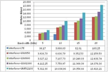
The best throughput performace value achieved at 2100 MHz while LTE interfered by GSM850 in 20 MHz is17,5 Mbps, also while interfered by GSM900 in 20 MHz is18,1 Mbps and interfered by GSM1800 in 20 MHz is18,1 Mbps.
Figure 4.3 Throughput for frequency 2100MHz
Figure 4.1 until Figure 4.3 shows that the smallest throughput occurs when LTE interfered by LTE as well. Despite, if LTE interfered by other technologies such as GSM and UMTS has the same pattern that the higher the bandwidth, the higher the throughput
B. SINR ANALYSIS
In this simulations, the SINR parameter value is -40dB for bandwidth 5MHz and 10 MHz, otherwise -45dB for bandwidth 15MHz and 20 MHz.
Similar to throughput and dropped user, the performance of LTE when interfered by LTE is in the lowest value than interfered by GSM and UTMS. While LTE is interfered by GMS and UMTS, its has the same patterns. It can be shown that while LTE is interfered by LTE, SINR reaches the highest value at 900MHz is bandwidth 10 MHz is -10,89 dB
Figure 5.1 SINR for frequency 900MHz
The worst cases happenned at bandwidth 15Mhz while LTE is interfered by LTE. Same case The best SINR value is achieved while LTE 1800MHz is interfered by UMTS2100 due value is -0,92 dB at 5Mhz of bandwidth. It might happened because different frequencies is interfered by different systems at different frequencies too.
The same cases happened in the value of throughput performance. At bandwodth 20 MHz, when LTE 900 MHz interfered by GSM 900 the SINR value that appears is NaN (undefinite), this may happen because the same frequency interfered by different systems on the same frequency.
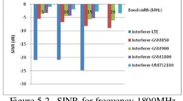
Figure 5.2 SINR for frequency 1800MHz
Getting simulated the SINR for frequency 900 Mhz, the value achieved the best performance at 5Mhz of bandwitdh while LTE is interfered by UMTS2100 which is 2,16 dB. It might happenned because different frequencies is interfered by different systems at different frequencies also.
The same case happened like at 900 MHz, when LTE 1800 MHz in 20 MHz interfered by GSM 1800 the SINR
Figure 4.3 SINR for frequency 2100MHz
value that appears is NaN (undefinite), this may happen because the same frequency interfered by different systems on the same frequency.
frequency interfered by different systems on the same frequency.
C. THROUGHPUT VS SINR ANALYSIS
Basically, SINR’s increase in line with the increase of throughput which is interfered. This chart pattern in accordance with the pattern of the graph in Figure 2.5 and the equation 3.4 which shows the relationship between throughput with SINR.
Figure 6.1 LTE interfered by LTE; Throughput vs SINR
Despite, it can be seen at Figure 6.1 that the best value in received throughput and SINR cases in frequency 900 MHz on 10 MHz while LTE interfered by LTE is -10,89 dB and up to 3 Mbps.
Figure 6.2 LTE interfered GSM850
The best performance occurs while LTE is interferrred by GSM850 at 2100 MHz in 20MHz of bandwidth which the value is 18,145 Mbps and SINR at 1,12 dB.
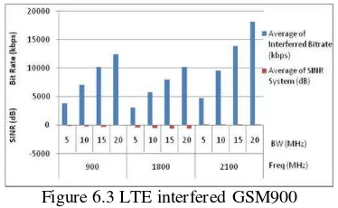
Figure 6.3 LTE interfered GSM900
The same case happened while LTE interfered by GSM900, the best performance achieved at 2100 MHz in 10
Mhz of bandwidth which value is 18,312 Mbps and SINR 1,52 dB. It is also happened in Figure 6.4 while LTE interfered by GSM1800, with the value is 18,353 Mbps and SINR 1,5 dB. That case might happen because at 2100 MHz the bandwidth is greater that other bands of frequencies.
Figure 6.4 LTE interfered GSM1800
While LTE 900MHz interfered by GSM 900MHz then SINR’s value in 20MHz occurred NaN (undefinite), it maybe occurs because different technology using same frequency bands. It happenned in the same case while LTE 1800 MHz interfered by GSM 1800MHz.
From Figure 6.1 until Figure 6.5, can be shown that the greater the allocated bandwidth, the greater the throughput obtained. In line with this, that the greater throughput obtained then the better the SINR. This is in line with equation 3.1.
Similar to other frequencies, which is currently LTE 2100 MHz interfered by UMTS 2100MHz, so SINR’s value in 20MHz are NaN (undefinite). This likely occurred because the same frequency band using two different technologies, so the results of SINR’s value are NaN (undefinite).
Figure 6.5 LTE interfered UMTS2100
V. CONCLUSION AND FUTURE WORK
The importance of refarming and interconnection scheme is fair for the state to encourage operators to build networks as a form of fulfilling commitments and to build a network license is not limited only in big cities.
frequencies band options, LTE can well coexist with other technologies in the ecosystem such as GSM and UMTS that can be seen from throughput and SINR performance.
Overall simulation showsthe performance of 2100 MHz is the best value while LTE is interfered by other systems such as GMS and UMTS in terms of SINR and throughput as well.
For further research, it would be needed to explore and compare the performance analysis while using another simulations such as Matlab and NS3. Also it can be analyze with different parameter.
REFERENCES
[1] ElNashar, A., El-saidny, M., & Sherif, M. (2014). Design, Deployment and Performance of 4G-LTE Networks : A Practical Approach. Wiley.
[2] Hung Ng, M., Lin, S.-D., Li, J., & Tatesh, S. (2009). Coexistence Studies for 3GPP LTE with. IEEE Communications Magazine .
[3] European Communications Office. (2010). SEAMCAT Manual Handbook. Denmark: ECO / Project SEAMCAT.
[4] 3GPP TR 43.030, v. 9. (2010). Digital cellular telecommunications system (Phase 2+);Radio network planning aspects. France: ETSI TR 143 030 V9.0.0 (2010-02).
[5] Adu, O. I., Idachaba, F. E., & Alatishe, A. A. (2014). Refarming 1800MHz GSM Spectrum to LTE: The Effects on Coverage Based on Pathloss Estimation. Proceedings of the World Congress on Engineering 2014 Vol I. London: WCE.
[6] Sainju, P. M. (2012). LTE Performance Analysisi on 800 and 1800 MHz Bands. Tampere: Tampere University of Technology.
[7] (2011). Coexistence of GSM-HSPA-LTE. 4G Americas.
[8] Aryanta, D. (2012). Analisis Pengalokasi Kanal Frekuensi Long Term Evolution di Indonesia. Jurnal Informatika .
[9] Gillet, Joss. (2012). https://gsmaintelligence.com/ research/2012/09/spectrum-refarming-at-1800-mhz-key- to-lte-device-adoption/349/.
[10] GSMA. (2011). Mobile Broadband in the 1800MHz Band.
[11] Hendraningrat, D. K., A, N. M., Usman, U. K., & Setiawan, D. (2011). Re-farming of Frequency 700MHz Anlysis for Long Term Evolution (LTE) in Indonesia Using Link Budget Calculation. Internation Conference on Electrical Engineering and Informatics. Bandung.
[12] Nera Economic Consulting. (2011). 900 MHz and 1800 MHz band Refarrming Case Study ; France. Washington.
[13] Purohit, A. (2013). LTE in the Middle East Region- Spectrum Refarming PAving Way Forward. Cisco Communities .
[14] Setiawan, D. (2010). Alokasi Frekuensi Kebijakan Penggunaan dan Perencanaan Spektrum Indonesia. Jakarta: Departemen Komunikasi dan Informatika. [15] White Paper. (2013). Interference in Cellular Networks :
Intermodulation and Frequency Refarming. JDS Uniphase Corporation.
[16] Yahya, A. T. (2011). Understanding LTE and its Performances. France: Universty Paris Stud-11 Laboratoire de Recherche en Informatique Orsay Cedex.
[17] Zhang, H., Chu, X., & Wen, X. (2013). 4G-Femtocells Resource Allocation and Interference Management. London: Springer New York Heidelberg Dordrecht. [18] Zubin Bharucha. (2012). LTE/LTE-A Interference
![Figure 1.1 Evolution from 2G/3G/HSPA(+) to LTE [1]](https://thumb-ap.123doks.com/thumbv2/123dok/4029887.1973307/1.596.320.562.522.619/figure-evolution-from-g-g-hspa-to-lte.webp)