and Bus Systems
for Communication
Practical fundamentals
- it is used for configuring and setting the parameters for microprocessor instruments
- serial bus systems, with minimum wiring requirements, are able to acquire a large amount of de-centralized information and distribute it to the process equipment. Intelligent field and automati-on devices can communicate directly with automati-one another via a digital bus.
This book is intended as a step-by-step introduction to the subject of digital communications, for practical engineers and those new to this field. The emphasis is on clarifying generalized topics, as well as including some JUMO-specific applications.
In this revised edition, the material on bus systems has been extensively updated. The method of operation of bus systems for which JUMO has field devices available is explained in a practical man-ner.
Special thanks are due to all our colleagues, who helped us to prepare this book with their coope-ration and professional input.
Fulda, March 2001
Manfred Schleicher Frank Blasinger
English translation of the 3rd. edition (revised) M.K. JUCHHEIM GmbH & Co, Fulda
Copying permitted with source reference!
1
Basic principles of digital interfaces and networks ... 3
1.1
Analog/digital signals
...
3
1.2
Data encoding
...
7
1.3
Types of data transmission
...
13
1.3.1
Operating modes of a transmission medium ... 17
1.3.2
Speed of data transmission ... 18
1.4
Media for data transmission
...
20
1.4.1
Transmission quality and cable terminating resistance ... 22
1.4.2
Modem ... 23
1.5
Properties of various interfaces
...
25
1.6
Networks and bus operation in automation
...
38
1.6.1
Communication networks and levels ... 40
1.6.2
Fieldbus topologies ... 44
1.6.3
Centralized and distributed arrangement of automation devices ... 48
1.6.4
Access methods ... 49
1.6.5
Bus communication ... 54
1.7
OSI reference model
...
57
1.8
Network management
...
61
1.8.1
Functions of MAC and MAP ... 61
1.8.2
The data structure ... 64
1.8.3
Error checking ... 66
1.8.4
Connection of networks via repeater, bridge, router and gateway ... 68
1.9
Operation through application programs
...
72
1.9.1
Configuration software (setup program) ... 73
1.9.2
Project design software ... 75
1.9.3
Measurement display and operation using visualization/evaluation software .... 76
2
Important fieldbus systems ... 81
2.1
HART communication
...
83
2.2
ASI bus
...
85
2.3
Bitbus
...
86
2.4
CAN bus
...
88
2.5
FIP bus
...
93
2.6
Interbus
...
94
2.7
LON bus
...
96
2.8
Modbus
...
97
2.9
P-Net
...
98
2.10
PROFIBUS
...
100
2.11
FOUNDATION fieldbus
...
105
2.13
Summary of the fieldbus systems
...
111
3
Organization of the data system for JUMO ... 113
3.1
The various communications options
...
114
3.1.1
Physical interfaces ... 114
3.1.2
Transmission protocols and fieldbus systems ... 114
3.2
JUMO instruments with HART
...
116
3.3
JUMO instruments with CANopen
...
118
3.4
JUMO instruments with LON
...
120
3.4.1
The JUMO mTRON concept ... 120
3.4.2
Network structure ... 122
3.4.3
Hardware architecture of a LON device ... 123
3.4.4
Communication procedure ... 124
3.5
JUMO instruments with Modbus/Jbus
...
126
3.5.1
Physical interface and data flow ... 126
3.5.2
Master/slave principle ... 127
3.5.3
Transmission mode ... 128
3.5.4
Format of the data blocks ... 129
3.5.5
Connection via an interface converter ... 130
3.6
JUMO instruments with PROFIBUS
...
132
3.7
Checklist for fault-finding in serial interfaces
...
134
4
Outlook ... 137
4.1
Standards and technologies in automation engineering
...
137
4.1.1
NOAH (Network Oriented Application Harmonization) ... 137
4.1.2
OPC (OLE for Process Control) for communication ... 138
4.1.3
Ethernet fieldbus equals system bus ... 141
4.2
Long-distance data transmission
...
143
4.3
Distributed systems
...
145
This chapter deals first of all with some basic principles. The aim here is to achieve this without over-complex theoretical or mathematical treatment. Amongst other things, the basic facts about data encoding, types of data transmission, properties of different interfaces, construction of networks etc. are explained for practical engineers, who are increasingly faced with the sub-jects of digital communication and bus systems in modern automation engi-neering.
1.1
Analog/digital signals
In today’s automation engineering, more and more devices operate digitaIly. This is in contrast with the more familiar analog measurement technology and data transmission. This means that digital process instruments are increasing-ly replacing analog type instruments in modern process control, part because of the technological advances and the advantages offered. Nowadays, digital transmission is even superseding the use of familiar standard signals such as 4 — 20mA, 0 — 10V, etc. for the transfer of analog measurements. The main features of different data transmission technologies are explained in more detail below.
Analog signals
A measurement, a temperature for example, is converted into a signal corre-sponding to this temperature by a measuring device. The signal could be, for instance, a 4 — 20mA current. Every temperature value corresponds clearly to a value of electrical current. If the temperature changes continuously, the ana-log signal also changes continuously. In other words, a characteristic feature of analog transmission is that the amplitude of the selected signal varies con-tinuously over time (see Fig. 1).
In automation engineering, such standard signals (4 — 20mA) are transmitted in pure analog form as a normalized current signal. A temperature value is measured by a Pt100 resistance thermometer, then converted into a current proportional to the measurement by a transmitter, and subsequently transmit-ted to a controller, indicator and recorder (see Fig. 2). By means of the current, every change in measurement value is immediately recorded by each instru-ment connected in the circuit.
Fig. 2: Analog signal transmission
In measurement engineering, the information content of an analog signal is very limited in comparison with acoustic (sound) or optical (light) data trans-mission. Apart from the advantages of an unambiguous, continuously repro-duced measurement, with simultaneous supply of power to the measurement recorder (e.g. two-wire transmitter), the information content of the analog sig-nal consists only of the magnitude of the measurement, and whether or not the signal is available at the connected device.
Digital signals
The term “digital” is derived from the word “digit” and comes originally from the Latin “digitus = finger”. Digital means sudden or step changes, i.e. a digital signal does not vary continuously.
In the example of temperature measurement, this means that the analog mea-surement is divided into specific value bands, within which no intermediate values are possible. The values are read at fixed time intervals, the sampling time. The task of conversion is carried out by an analog to digital converter (or ADC). Here, the accuracy or resolution of the signal depends on the number of value bands and the sampling frequency.
Fig. 3: Digitized measurement signal
The digitized quantity has only the two values “high = 1” and “low = 0” and must now be transmitted as a data packet by a microprocessor (µP)-transmit-ter with an in(µP)-transmit-terface (see Fig. 4). The measurement is transmitted encoded as a packet, and has to be decoded by the receiver (see also data encoding, Chapter 1.2). The transmission mode can vary: by different voltage levels, light pulses or a sequence of notes.
Fig. 4: Digital signal transmission
Fig. 5: Analog and digital cabling
1.2
Data encoding
We have already noted that some form of encoding into electrical signals is re-quired first of all for data transmission. With analog transmission, the informa-tion is transmitted by means of the amplitude. Digital technology has only two states, “On = logic 1” and “Off = logic 0”, which are usually transmitted by means of different voltage levels. Various codes and protocols, which must be understood by all communication partners in the data system, are used for transmission of digital quantities.
The most common codes and protocols are investigated in more detail in this chapter and later on in the book.
Bit and byte
Bit The bit is the unit for a binary (two value) signal, corresponding to a single dig-ital data unit that has the value “1” or “0”, The term bit, an abbreviation for bi-nary digit, is very commonly used as the smallest unit in information technolo-gy.
As already described, the signals logic “1” and logic “0” are usually represent-ed by voltage signals with different levels (see Fig. 6). The voltage levels usrepresent-ed depend on the type of interface employed.
Fig. 6: Binary data transmission in “bits” using different voltage levels
Byte The term byte was introduced for a unit with 8 binary characters. A byte has a length of 8 bits (see Fig. 7). In an automation device (PLC), for example, the signal statuses of 8 logic inputs or outputs are combined into either an input byte or an output byte. Correspondingly, for example, 64 bits = 8 bytes, 72 bits = 9 bytes etc.
Fig. 7: Combination of “8 bits” to give “1 byte“
Word A sequence or string of binary characters that is regarded as a unit in a partic-ular context is designated as a word. A control instruction in a PLC or a com-mand in a communications protocol has, for example, 1 word, 2 bytes or 16 bits. In many automation devices, 16 logic inputs or outputs are combined to give either an input word or an output word (see Fig. 8).
Fig. 8: Representation of a data word using “2 bytes“
Double word A double word has 2 words, 4 bytes or 32 bits.
Binary system The best known and most important number system is the binary number sys-tem, usually referred to as the binary system. Each position in a binary number is assigned a power of 2. Fig. 9 shows the basic structure of the system. If a place value is zero, a “0” is entered instead of a “1”.
BCD code (8-4-2-1 code)
The name BCD (binary-coded decimal) means a decimal number expressed in binary code. The main aim of this frequently used code is to represent the dec-imal numbers by 0 and 1, using the binary system. In this case, the highest value decimal number is 9. To express the number 9 in binary code requires 4 power of 2 places in all (see Table 1).
Table 1: Representation of the decimal numbers up to 9 in BCD code
Four binary places (also referred to as a tetrad) are required to represent the highest decimal number. The BCD code is thus a 4 bit code. We can see that it very easy to transmit a decimal number to an automation device, a PLC for ex-ample, by expressing the number as a bit muster in 8-4-2-1 code.
ASCII code However, not only numbers have to be transmitted, but also letters, punctua-tion marks etc. For this we use coding tables in which each number is as-signed a letter, number or symbol. The ASCII code (American Standard Code for Information Interchange) is very widely used in this connection. In addition to characters and numbers, special characters and control characters are also defined here (see Table 2).
Decimal number
23 22 21 20
8 4 2 1
Table 2: ASCII code
ASCII value Charac- ter Con
tr
o
l
charac- ter ASCII value Charac- ter ASCII value Charac- ter ASCII value Charac- ter
000 null NUL 032 (space) 064 @ 096
001 SOH 033 ! 065 A 097 a
002 STX 034 „ 066 B 098 b
003 ♥ ETX 035 # 067 C 099 c
004 ♦ EOT 036 $ 068 D 100 d
005 ♣ ENQ 037 % 069 E 101 e
006 ♠ ACK 038 & 070 F 102 f
007 (Alarm) BEL 039 ´ 071 G 103 g
008 BS 040 ( 072 H 104 h
009 (Tabulator) HT 041 ) 073 I 105 i
010 (Line Feed) LF 042 * 074 J 106 j
011 (Home) VT 043 + 075 K 107 k
012 (Form Feed) FF 044 , 076 L 108 l
013 (Carriage Return) CR 045 - 077 M 109 m
014 SO 046 . 078 N 110 n
015 SI 047 / 079 O 111 o
016 䉴 DLE 048 0 080 P 112 p
017 䉳 DC1 049 1 081 Q 113 q
018 ↕ DC2 050 2 082 R 114 r
019 !! DC3 051 3 083 S 115 s
020 ¶ DC4 052 4 084 T 116 t
021 NAK 053 5 085 U 117 u
022 – SYN 054 6 086 V 118 v
023 ↕ ETB 055 7 087 W 119 w
024 ↑ CAN 056 8 088 X 120 x
025 ↓ EM 057 9 089 Y 121 y
026 → SUB 058 : 090 Z 122 z
027 ← ESC 059 ; 091 [ 123 ~~
028 (Cursor right) FS 060 < 092 \ 124
-029 (Cursor left) GS 061 = 093 ] 125 ~~
030 (Cursor up) RS 062 > 094 ↑ 126 ~
031 (Cursor down) US 063 ? 095 – 127 왕
It is noticeable that the ASCII standard only caters for 128 characters, and these can be represented by using 7 bits (27 = 128). Bear in mind that the zero counts as a number, hence 128 characters. The eighth bit has no significance in the ASCII code; originally it was assigned as a parity bit (see forms of data transmission, Chapter 1.3).
In this code, the characters from decimal 0 to 31 are control codes, from 32 to 63 numbers and from 64 to 127 mainly upper and lower case letters. However, with 128 characters, some special characters such as umlauts, “§” etc. cannot be represented. For this reason, the code is extended to 8 bits, and can then represent a total of 256 characters (28 = 256). Today, the extended 8 bit form is used almost exclusively.
Here is a short example of transmission of a character using the ASCII code. The letter “J” is to be transmitted to an automation device. This takes place as follows:
- Conversion into ASCII code: “J” = 74
- Conversion into a bit muster and transmission: 74 = 1 0 0 1 0 1 0
- Decoding the bit muster in the receiving device:
1 0 0 1 0 1 0 = 1 x 26+ 0 x 25+ 0 x 24+ 1 x 23+ 0 x 22+ 1 x 21+ 0 x 20 = = 64 + 0 + 0 + 8 + 0 + 2 + 0 = 74 - Conversion using ASCII code:
74 = “J”
This may all appear to be very time-consuming, but modern microprocessor devices can carry out the encoding and decoding in an extremely short time. There are other codes as well as the ASCII code, for example IEEE 754 (Stan-dard for Binary Floating-Point Arithmetic) issued by ANSI (American National Standard Institute) in 1985. It deals with the representation of signs, exponents and mantissas of a floating-point number.
Hexadecimal system
Table 3: Comparison of decimal, hexadecimal and binary numbers
We can see that the carry occurs at decimal 16 = 0010 hex. When converting a hexadecimal number to a binary number, each hex. number corresponds to a four bit binary number with the equivalent value, and vice versa. A micropro-cessor would interpret a binary number that it receives as follows:
Binary 0001 1011 1111 1100
Hex 1 B F C
Decimal Hexadecimal Binary 0 1 2 3 4 0000 0001 0002 0003 0004 0000 0001 0002 0011 0100 5 6 7 8 9 0005 0006 0007 0008 0009 0101 0110 0111 1000 1001 10 11 12 13 14 15 000A 000B 000C 000D 000E 000F 1010 1011 1100 1101 1110 1111
1.3
Types of data transmission
Having explained the principles of data encoding, we now turn to the question of how the individual data are transmitted.
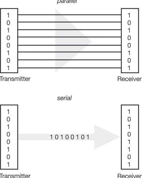
Parallel transmission
The most obvious solution is to transmit the data in bytes over a minimum of 8 lines, so that each line is assigned a switching state or bit. This is referred to as parallel transmission or parallel interface (see Fig. 10). With the parallel inter-face, the 8 data bits that, for example, are transmitted from the computer to the printer for each letter, are transmitted simultaneously over 8 lines. The Centronics and IEEE 488 interfaces are familiar versions here.
Parallel data traffic permits a high transfer rate, as each block of 8 bits (and even 16 or 32 bits with more advanced systems) is transmitted simultaneously. The disadvantages are the high cabling costs and the susceptibility of parallel transmission to interference as the distance increases. For this reason, the parallel interface is only used over short distances.
Serial
transmission
It is advisable to use serial data transmission (interface) for longer routes and because of its reduced susceptibility to interference (see Fig. 10). Here the 8 data bits are sent one after the other, e.g. over a two-wire circuit. It is signifi-cantly slower than the parallel method, but has been accepted in automation engineering because of its suitability for bus systems. The RS485 interface is well known here, and will be described in more detail later in the book.
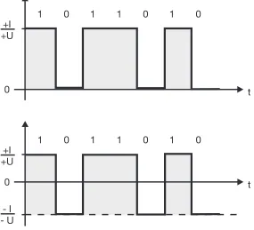
The electronic circuitry of a suitable interface has the task of transmitting the digital information via a medium. One method is the D.C. current / D.C. voltage pulse method, the outstanding feature of which is the very simple transmitter and receiver construction. Information can be transferred by:
- switching a current on and off - switching a voltage on and off
- switching a voltage from a negative to a positive potential - changing the sign of a voltage difference (see Fig. 11).
Fig. 11: D.C. current and voltage pulse methods
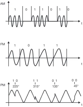
There is also the familiar A.C. methods, predominantly used for data transmis-sion in the telephone network. The signals are normally transmitted as:
- amplitude modulated (AM) signals - frequency modulated (FM) signals
Fig. 12: A.C. current pulse methods
Pulse code modulation
Digital data transmission is becoming increasingly important in modern data transmission. With pulse code modulation, no analog signals are used, and only digital signals are transmitted. Amplifier noise suppression is simplified using this method. The technique is widely used to improve quality in home electronics, e.g. with the CD (compact disk).
Where telephone channels are transmitted over digital networks, this method is used in the ISDN (Integrated Services Digital Network) for voice transmis-sion etc.
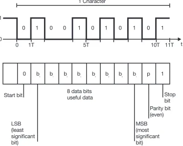
Asynchronous transmission
With the asynchronous method, each transmitted byte or code word is en-closed between two synchronization characters. Each character transmitted begins with a “start bit” followed by the actual information (one or even several bytes). The termination is made up of the “parity bit” test character and one or two “stop bits” (see Fig. 13).
Fig. 13: Composition of a telegram with asynchronous data transmission
The task of the start bit is to establish synchronism between the transmitter and the receiver. The start bit is issued by the transmitter and indicates that a character of data now follows. The data line is held in a mark or “1” condition when no data is being transmitted, and is set to the space or “0” condition by the start bit.
The “stop bit” reports that the transmission of the data is complete and resets the transmission medium from “0” to “1”. Depending on the system used, 1 or 2 stop bits are possible.
In other words, this means that for transmission of a character, the receiver synchronizes its clock with the start bit. To a large extent, the transmitter and receiver are in synchronism for the duration of the transmission; synchronism is lost again after the stop bit. As the clocks only run in synchronism for a short time, this is referred to as asynchronous data transmission.
checking, the parity bit is set so that checksum of the data and parity bits pro-duces an even number, and with odd parity checking an odd number. For its part, the receiver forms the checksum of the digits of the character received and compares it with the status of the accompanying parity bits. The example in Fig. 13 illustrates even parity checking, as the sum of the digits is four with the parity bit set at 0. Error correction is clearly not possible with this method. However, there are rather more complicated methods which do allow error correction.
The advantages of this type of transmission lie in the low hardware costs and a simple, easily understood data protocol. It is particularly suitable for short messages and is often used for communication in fieldbus systems. The dis-advantage is the additional bus loading, caused by the constantly recurring start and stop bits.
Synchronous transmission
With synchronous transmission, a timing signal (character) is generated by the transmitter and used for control of the transmission. The receivers are syn-chronized with one another by means of this timing signal, i.e. the point at which they transfer data is determined. This character must be repeated at regular intervals (every 100 to 1024 data bits).
The advantage of synchronous transmission is that a large data block can be transferred within a short time window. Disturbances on the transmission me-dium can be a disadvantage, and can lead to loss of synchronism. Another disadvantage is the higher hardware cost of the transmitter and receiver.
1.3.1 Operating modes of a transmission medium
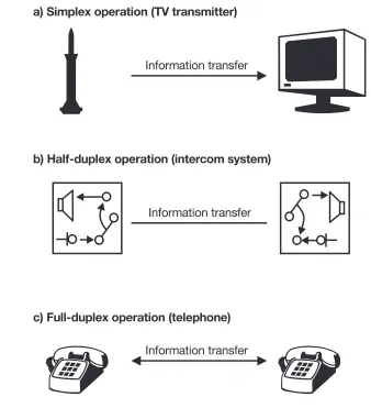
The direction in which data can be transmitted between various subscribers or nodes is of considerable importance. In general terms, three distinct operating modes for data traffic can be identified (see Fig. 14).
Simplex operation
Transmit or receive operation. Data transfer is possible in one direction only. This operating mode is rarely used in data processing, as the receiver has no possibility of replying. Good examples are radio and television transmitters, which all operate in simplex mode. The transmitter sends out a program, irre-spective of whether it is received or not (see Fig. 14a).
Half-duplex operation
Alternate operation. Data transfer is possible in both directions, not simulta-neously however, but alternately, one after the other. This operating mode is most often used in data processing and fieldbus systems. Examples are: inter-com systems, CB radio or remote scanning via telefax (see Fig. 14b).
This mode is also known as bidirectional (in both directions). JUMO instru-ments fitted with an interface can operate bidirectionally in half-duplex mode, i.e. they can transmit and receive data, but cannot do both at the same time. Full-duplex
operation
Full-duplex operation may not necessarily be possible, even if separate send and receive lines are available to interconnect two automation devices. This is because the hardware and software devices are unable to send and receive data simultaneously. Separate lines are more likely to be used, to avoid the cost of the switching equipment required to change over from transmit to re-ceive mode.
Fig. 14: Data transmission operating modes
1.3.2 Speed of data transmission
Another criterion for data transmission is the speed (baud rate). By this is meant the number of binary signals transmitted per unit time i.e. how many bits per second (bit/sec or bps) are transmitted between transmitter and re-ceiver. To be able to understand one another, all automation devices connect-ed together must communicate at the same speconnect-ed.
1.4
Media for data transmission
The transmission medium or cable itself represents a further important aspect, as transmission speeds are continually increasing. The correct cable is vital in industrial data transmission too, particularly with regard to interference. The main differences between the various transmission media are the transmission speed, the material costs and the ease of laying.
Primarily, the medium used depends on the protocol employed. This deter-mines the physical characteristics of the interface and with it the transmission medium that can be used. In the same way, the possible cable length is speci-fied, which depends mainly on the interface’s susceptibility to interference, the baud rate, and the resistance and capacitance of the cable. For practical ap-plications, the following media are presently available.
Shielded and unshielded twisted-pair cable
Unshielded twisted-pair cable
Unshielded twisted-pair cable (UTP) offers the most cost-effective solution with the easiest installation. It is relatively well-known from telephone technol-ogy. However, it is not widely used as a transmission medium, because of the low transmission speed and limited transmission distance achievable. In addi-tion, this type of cable is susceptible to EMC interference.
Using this transmission medium, a range of 100 – 200m at a speed of up to 167 kbps can be attained.
Shielded twisted-pair cable
Shielded twisted-pair cable (STP) is a better alternative. This is a cable with two individually shielded twisted-pairs and an overall outer shield or screen. Depending on the physical interface, twisted-pair cables with multiple cores are also used.
In today’s automation technology, the shielded twisted-pair cable is the most widely used transmission medium. The range is from 1000 — 3000m at a transmission speed of over 1Mbps.
Coaxial cable A number of messages can be transmitted simultaneously with a coaxial ca-ble. The main area of use for this transmission medium is in computer net-works, e.g. Ethernet in office communications. It is rarely used at field level, as it is more expensive than the twisted-pair cable, and also more difficult to in-stall. The advantages of this type of cable are the high transmission speed and good noise immunity.
The range can be up to several thousand meters, but the planned length of each bus segment should not normally exceed about 500m, because of the specific attenuation. The transmission capacity is up to 300Mbps.
Optical fiber waveguide
The optical fiber waveguide or fiber-optic cable is tremendously efficient and is becoming more and more significant in modern data transmission. Pulses of light, rather than electrical pulses, are transmitted through this cable. Hence this cable is immune to electromagnetic interference.
signal appears almost unchanged at the end of the cable. The multi-mode fi-bre operates in a different way. The light splits into a number of beams that travel through the cable by reflection at the boundary. This gives rise to transit-time differences and the signals appear somewhat more dispersed at the end of the cable. Because of this, the bandwidth available for signal transmission is rather limited with this type of cable.
Fig. 15 Principle of an optical fiber waveguide
One small disadvantage of this technology is that the application is limited to point-to-point connections.
Because light represents a form of energy, in exactly the same way as does an electric current, it too cannot be transmitted without losses. Ranges of up to several kilometers can be achieved with real glass fibers, but amplifiers must be fitted every 2 – 3 km. Transmission speeds of the order of gigabit/sec are possible with this medium.
1.4.1 Transmission quality and cable terminating resistance
The quality of transmission relative to the cable length depends on a number of factors:
Noise
susceptibility
- Noise susceptibility of the physical interface type used.
Noise effects - Effects of noise on the cable and their avoidance through the use of shield-ed twistshield-ed-pair cable etc. When a shieldshield-ed bus cable is usshield-ed, it is recom-mended that the screen is connected to the protective earth at both ends of the cable, using a low inductance connection, in order to achieve the best possible electromagnetic compatibility (EMC). Of course, the installation of interface cables should be sensibly planned, so that they do not run in close proximity to contactors, thyristor controllers, inverters, motors, trans-formers, or parallel to A.C. power cables or D.C. cables that are used for switching inductive loads, etc.
Transmission speed
- Transmission speed (baud rate). High transmission rates demand an opti-mally installed transmission medium and, for the most part, shorter trans-mission paths.
Capacitance - Capacitance of the cable. The cable is not a valueless medium, whose electrical properties can be neglected. It is a passive four-terminal network with constant electrical values (series resistance R, inductance L, cross re-sistance G, capacitance C). In other words, with these values, the cable represents a lowpass filter, and the higher the transmitted frequency, the more the transmitted signal is distorted.
For this reason, the characteristic values for the bus cable, as laid down by the standards or specifications, should always be observed (see, for exam-ple, DIN 19 245 Part 1, Para. 3.1.2.3).
Cable termination
Another important point for data transmission is the cable termination. At high-er transmission speeds (< 200 kbps), the use of a cable thigh-erminating resistor is recommended, in order to retain signal rise times and to keep reflections as small as possible. The terminating resistor “Rt” should be as nearly as possi-ble equal to the characteristic impedance of the conductor pair in the frequen-cy band of the signal spectrum.
.
Fig. 16: EIA RS485 Standard cable termination to DIN 19 245 Part 1
1.4.2 Modem
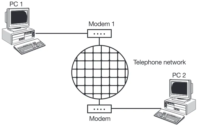
The word “modem” is a combination of the terms MOdulator/DEModulator and describes a device that processes binary data for transmission over a telephone line. Consequently, modems allow data to be transmitted over sub-stantial distances. The signals are forwarded over the telephone network, by radio or by satellite.
Modem A modem receives data in digital form, for example from a computer, and con-verts this to an analog signal, so that it can be carried over the telephone line, demodulated at the other end by a second modem, and thus made available in digital form again (see Fig. 17).
As long as the majority of installed telephone connections are based on con-ventional analog technology and do not make use of the new ISDN network, then, for the time being, modems will retain their importance for data transmis-sion. However, the ISDN (Integrated Services Digital Network) will increasingly replace the existing analog telephone network in Europe. It combines the use of speech, text, graphics and data in a single network. The difference between ISDN and the existing network is that, in ISDN, the signals are transmitted ex-clusively in digital form to the terminal device. The existing telephone lines can still be used for this digital transmision.
This means that, instead of using a modem to convert the digital signals of a PC to analog form, it is possible to use an ISDN controller card for direct data communication via ISDN. Normally, the connection takes place via the Basic-Rate Interface (BRI). Subscribers are given access to the S0 bus via an S0 in-terface (four-wire inin-terface) for up to eight terminal devices, of which two can be used simultaneously. The bus has two 64 kbps user channels (B-channels) and one 16 kbps signalling channel (D-channel).
1.5
Properties of various interfaces
To establish communication in automation engineering, different devices from various manufactures have to be connected together. For successful data transfer, the correct cable must be chosen, and the interfaces of the devices must be identical. To this end, several interface standards have been estab-lished and specified in various standards.
Table 4 sets out a number of properties of some well-known interfaces.
Parallel interfaces, such as the IEC bus, also known as IEEE 488 or IEC 625, are not suitable for industrial use, because their noise susceptibility is too high and the cabling is cost-intensive. RS232 (V.24) and TTY (20mA) interfaces are still very widely used for point-to-point connections. The physical properties of the RS422 and RS485 interfaces make them very robust, and they are now ac-cepted as serial interfaces in the field area, because of their suitability for bus operation (see Chapter 1.6 “Networks and bus operation in automation”) and their high noise immunity. The suitability for bus operation reduces the cost of connection and cabling, and the noise immunity permits long cable lengths.
Table 4: Properties of various interfaces
Serial interfaces Parallel
interfaces
TTY (20mA) RS232 (V24) RS422 RS485 IEC (IEEE 488)
Signal states logic 0/logic 1
20mA/0mA +3V to / -3V to +15V / -15V
-5V / +5V +5V / -5V
-5V / +5V +5V / -5V
5V / 0V
Possible transmission modes asynchronous full-duplex asynchronous full-duplex asynchronous full-duplex asynchronous half-duplex asynchronous full-duplex Maximum cable length
1000m 30m 1200m 1200m 2 — 20m
Number of lines
4 min. 3
2 data 1 ground 4 (5) 2 transmitter 2 receiver (1 ground) 2 (3) 2 data (1 ground) 16 8 data 3 handshake 5 control Subscribers per interface transmitters/ receivers
1/1 1/1 1/10
without Repeater 32 transmitters/ receivers without Repeater 1/15 Maximum transmission rate
19.2kbps 19.2kbps 10 Mbps 10Mbps 2Mbps
Application Teleprinters, displays, hazardous (Ex) areas, CNC ma-chines PC peripherals, automation engineering devices PC peripherals, automation engineering devices PC peripherals, fieldbuses in automation Instruments and control devices for use in laboratories
Properties insensitive to noise, suitable for bus opera-tion, secure data transmis-sion insensitive to noise, widely used insensitive to noise,
suitable for bus operation
insensitive to noise,
suitable for bus operation, widely used
In principle, the type of interface has nothing to do with the method of data transmission, i.e. character-coding according to ASCII, the protocol used etc. Of course, the interface does determine whether bus operation, handshaking etc. are at all possible.
UART Interface drivers are integrated circuits which process the digital signals into interface-specific signals. A V.24 driver, for instance, gives the signal the re-quired maximum voltage levels of -15V and +15V etc. The processor output signals to the driver are always the same.
The interface driver itself is controlled by a “UART” (universal asynchronous receiver/transmitter) module (see Fig. 18). This converts the parallel data for-mat of the processor into serial forfor-mat, adds start and stop bits, calculates the parity bit etc. The data format is determined by the UART, the electrical format by the interface driver.
Abb. 18: Principle of interface processing into RS485 format
For this reason, DIN 66 258 Part 1, for example, refers to both TTY and V.24 in the same breath, although at first glance they appear completely different. However, if we set aside the handshake lines of the V.24 and ignore the differ-ent signal levels of the two interfaces, they are absolutely iddiffer-entical.
In contrast to TTY and V.24, the RS422 and RS485 interfaces are suitable for bus operation, requiring special software to manage the bus. Once again, the two interfaces are very similar to one another.
To check whether two devices can be connected via a digital interface, the in-formation in the handbook should be used to establish whether the various parameters, e.g. the data format, of each device are identical:
- Electrical characteristics
(determined automatically by the interface designation) - Data format (baud rate, parity bit, stop bits, word length) - Addresses
- Protocol, etc.
Interface converters
There are interface converters, some of them devices no bigger than a ciga-rette packet, which facilitate a conversion. For instance, if a device with a V.24 interface is required to transmit over a longer distance, or is to be connected to a number of devices, a conversion to RS422/RS485 can be carried out with this type of device. In the simplest type of interface converter, only the signal level is changed. As explained earlier, the data format, character-coding etc. are clearly not interface-specific (see Chapter 3.5.5 “Connection via an inter-face converter” ).
The most important data and properties of the serial interfaces (Table 4) used in today’s automation engineering are described below.
TTY interface
There are a number of different designations for the TTY (20mA) interface: line current, current loop, current interface. The TTY interface was originally devel-oped for teleprinters (“TeleTYpes”). Its official name is the C_S interface. The design guidelines are laid down in DIN 66 258 Part 1.
A current is used for data transmission. A constant current, normally 20mA, flows in the passive state.
As a result of this:
passive state (logic 0) = current “ON”“ active state (logic 1) = current “OFF”“
At first glance, the fact that the interface inverts may appear irrational.
Clearly, for a full-duplex operation, two current loops are required. When two devices with TTY interfaces are linked together, only one device provides the loop current, whilst the second device is “passive”. Interconnecting two active devices can lead to malfunctions. In general, the current source is electrically isolated from the device.
As a general rule, in industrial versions of the TTY, the signals are coupled in and out using opto-couplers (see Fig. 19). A current source (often integral in the device) supplies the line current, normally defined as 20mA. The open-cir-cuit voltage of the current source must not exceed 24V max. (see DIN 66 258 Part 1).
Because of the low internal resistance of the TTY interface, a number of devic-es can be connected in seridevic-es in a ring formation. The central computer then becomes a component part of the ring. Of course, this presupposes that suit-able software is availsuit-able to facilitate system management (device numbers etc.).
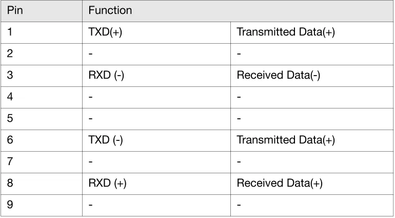
There is no standardized plug connection for this interface. Hence, the most suitable connector can be chosen for each specific application. A good solu-tion is a 9-way sub-D connector, as this is also used for many other interfaces (see Fig. 20). Table 5 shows the pin assignment and the corresponding func-tions. The transmit and receive signals are positioned opposite one another on the connector, in order to offer good termination possibilities for twisted-pair cables.
Fig. 20: Example of a connector used with the TTY interface
Table 5: TTY interface pin assignment and signals
Because of its high noise immunity, this interface can be used in a relatively “rough” environment and will achieve very high reliability. Table 4 provides
ad-Pin Function
1 TXD(+) Transmitted Data(+)
2 -
-3 RXD (-) Received Data(-)
4 -
-5 -
-6 TXD (-) Transmitted Data(+)
7 -
-8 RXD (+) Received Data(+)
-RS232C interface
The RS232C (V.24) interface is one of the best known serial interfaces. In Ger-many, it is often found under the designation V.24. In fact, the V.24 standard applies only to the functional values and the V.28 to the electrical values of the American RS232C standard. Generally speaking, “V.24” is taken to mean the electrical values as well. The electrical and mechanical data are laid down by the German Industrial Standards Organization (DIN) in the standards, DIN 66 020, 66 021 and 66 259.
The RS232C interface was originally designed to connect computers over telephone lines. Here, the computer (referred to as DTE, data terminal equip-ment) is connected by means of the interface to a modem (referred to as DCE, data communications equipment). The same arrangement is used at the other end to decouple the signals.
The RS232C interface defines a total of 20 lines. However, many of these are specially designed for modem features, such as the acknowledgement of sig-nal quality and the like. They are not required for data transfer, so that most of the 20 lines can be ignored.
RS232C and DIN standards use different nomenclatures. The DIN nomencla-tures are based on differentiating between ground, status, control, and data lines. However, the standard American abbreviations are used in the following description.
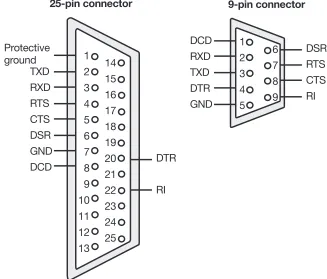
The pin assignments given in Table 6 refer to a 25-pin and a 9-pin sub-D con-nector (see Fig. 21). Normally a 25-pin sub-D concon-nector is used. The pin as-signments are applicable to data terminal equipment (DTE), see above. As only a few lines are used in practice, the 9-pin connector is used increasingly nowadays; it has a non-standard pin assignment and was originally introduced by IBM.
Pin number Signal abbreviation
Function Direction
9-pin 25-pin RS232 DTE
1 8 DCD M5 Data carrier detect In
2 3 RXD D2 Received data In
3 2 TXD D1 Transmitted data Out
4 20 DTR S1 Data terminal ready Out
5 7 GND E2 Signal ground
6 6 DSR M1 Data set ready In
7 4 RTS S1 Request to send Out
8 5 CTS M2 Clear to send In
9 22 RI M3 Ring indicator In
1 CG E1 Protective ground
9 TV+ Test voltage + Out
10 TV- Test voltage – Out
11 CK S5 High transmit frequency In 12 S DCD HM5 Secondary channel
data carrier detect
In
13 S CTS HM2 Secondary channel clear to send
In
14 S TXD HD1 Secondary channel transmitted data
Out
15 TXC T2 Transmit clock Out
16 S RXD HD2 Secondary channel received data
In
17 RXC T4 Receive clock In
18 nc Unassigned
19 S RTS HS2 Secondary channel request to send
Out
21 SQD M6 Signal quality detector In 23 CH S4 High receive frequency Out
24 nc Unassigned
The signal levels employed are a negative voltage of between –3V and –15V to represent the passive state (high) and a positive voltage of between +3V and +15V to represent the active state (low). The range between –3V and +3V is undefined (see Fig. 22).
Fig. 22: Voltage levels used with the RS232C interface
The V.24 and TTY interfaces are analogous in that the passive state corre-sponds to logic 0 and the active state to logic 1, so the V.24 interface also in-verts in the same way.
Handshake The RS232C interface also facilitates both hardware and software handshak-ing. The CTS and RTS lines can be used to implement a hardware handshake. A device can then only transmit when its CTS input is activated. The RTS out-put is activated to signal that the device is ready to receive.
(The ready to receive signal can be interpreted as meaning that the device is requesting another device to transmit data. This explains the expression “Switch on transmitter”)
The DSR and DTR lines are sometimes used for hardware handshaking. In addition, there is also the possibility of a software handshake, but this will not be discussed in detail here.
DTE, DCE
The V.24 interface has been adversely affected by the fact that it was originally only designed for connecting a computer to a modem, and not for the direct connection of two computers. For this reason, there are two different connec-tor arrangements, one for data terminal equipment (DTE) such as printers, computers, diskette drives etc., and another for data communications equip-ment (DCE) such as modems.
Today, as far as the PC sector is concerned, termnial devices such as mice, printers, plotters, etc. are largely connected to the RS232 interface.
Table 4 gives additional technical details.
Connection of JUMO instruments with RS232 interfaces
In modern process automation with its bus systems and networks, the possi-bility of connecting process devices via the RS232 interface now plays only a relatively unimportant role. The main reason for this is that only one receiving device can be connected to a transmitter. Hence, this type of communication, used for instance with a PC, will only be explained briefly.
On the latest versions of JUMO process instruments, this form of data com-munication is normally only used to configure the device from a PC using the setup program (see Chapter 1.9.1 “Configuration software”). With earlier ver-sions, e.g. controllers in the JUMO-DICON series, the serial interface is offered as a separate hardware item, for communication using suitable visualization software. The protocol for data transmission has a very simple structure and was developed using only the ASCII character strings.
JUMO instruments used 5 lines at the most, and normally only 3 lines of the V.24 interface (RXD, TXD, GND, CTS, RTS). A hardware handshake is possible with the CTS/RTS lines. These options can be checked in the appropriate in-terface description of these devices.
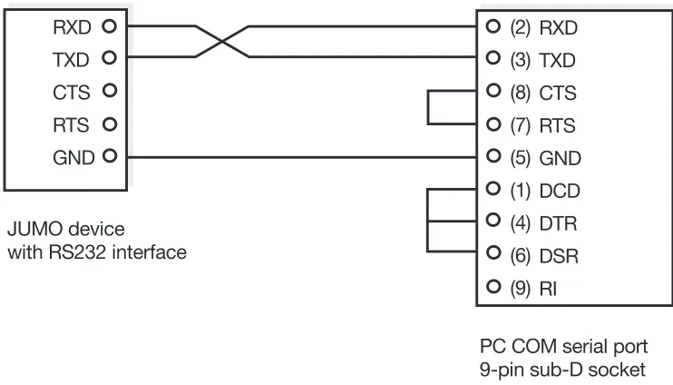
This results in the following wiring, for example, for interconnection of a JUMO DICON controller and a PC via the COM port (the example in Fig. 23 shows a connection without handshake). The pin arrangement refers to a 9-pin sub-D female connector.
Fig. 23: Interconnection of JUMO devices with RS232C interfaces, without handshake
RS422 interface
interface in comparison with the RS232 is its suitability for bus operation, as a number of subscribers can be attached. The individual technical data are sum-marized in Table 4.
The interface has symmetrical inputs and outputs, giving it a high noise immu-nity, as interference voltages coupled into the ground line have no effect on the signal.
Normally, this interface uses voltage differentials of 5V as the signal level, iden-tical to the TTL signal level. The voltage differential is always the same, only the sign of the differential is changed. If ground (GND) is not selected as the reference point, then when a logic 1 is transmitted, the voltage level is approx-imately -5V, and when a logic 0 is transmitted, the instrument reading would be +5V. The basic data connection consists of two lines, one for the normal signal (L+), and one for the inverted signal (L-) (see Fig. 24).
Fig. 24: Voltage levels with an abstracted RS422 interface
Discriminating between a positive and a negative voltage differential to read the logic level has a favorable effect on the noise susceptibility of the transmis-sion. Even though the received signal voltages may be very low, a reliable sig-nal level can always be assigned. A voltage differential of 0.3 V between the two inputs is sufficient for safe assignment of signal levels; the voltage differ-ential should not exceed 7V:
There is no standardized connector for this interface either. As with the TTY in-terface, a 9-pin sub-D connector can be recommended, and it is often used (see Fig. 25). Table 7 shows the pin arrangement and the associated functions.
Fig. 25: Possible connector for use with an RS422 interface
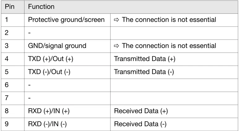
Table 7: Pin arrangement and signals of the RS422 interface
However, the connector arrangement should be taken from the corresponding handbooks in each case. The remaining free pins can be used to transmit con-trol signals. Here, as is the case with the TTY interface, neither ground nor supply voltage lines are normally carried. Although it is not essential in theory, it does however make sense to connect the signal ground (GND), if very differ-ent potdiffer-entials develop on the devices as a result of inadequate electrical isola-tion.
To increase the noise immunity over the transmission path, twisted-pair cables should be used, or better still, shielded twisted-pair cables. Depending on the application or requirement, the shield can then be connected to the protective ground or technical ground of the device or devices at one or both ends of the cable. Here, care should be taken to maintain strict segregation from the signal ground (GND).
Pin Function
1 Protective ground/screen v The connection is not essential
2
-3 GND/signal ground v The connection is not essential 4 TXD (+)/Out (+) Transmitted Data (+)
5 TXD (-)/Out (-) Transmitted Data (-)
6
-7
On JUMO process instruments with an RS422 serial interface, in addition to the four signal lines, the signal ground is always brought out to the connection terminals. The interconnection with a remote device (PC etc.) could then look like that shown in Fig. 26.
Fig. 26: Interconnection of a JUMO device with RS422 interface
RS485 interface
The RS485 interface, an EIA standard, once again lays down only the electrical and physical requirements. It was developed so that a higher number of bus subscribers could be connected for bus operation (see Chapter 1.6 “Networks and bus operation...”). Here, up to 32 subscribers, either transmitters or re-ceivers, can be connected to a 2-wire bus cable for a balanced data transmis-sion. Because of the balanced arrangement, a high noise immunity is achieved, as with the RS422.
There are no differences whatsoever between the method of transmission used by the RS485 interface and that used by the RS422 interface covered earlier. Both use the voltage differential method for the logic level. There are also no differences concerning the technical properties such as transmission speed and cable lengths. Even the same twisted-pair cable can be used. The single difference between the two interfaces is that, with the RS485, data can only ever be transmitted in one direction at a time, because, of course, only one bus is available. All devices, transmitters and receivers, are connect-ed to the same pair, i.e. they are all connectconnect-ed in parallel (see Fig. 27).
A PC is equipped with an RS232 interface as standard. An interface converter is required to operate an RS422 or RS485 interface (see Chapter 3.5.5 “Con-nection via an interface converter”).
As it is necessary to switch between transmit and receive modes, care must always be taken to ensure that only one transmitter accesses the bus at any one time. This is the job of the PC, bus system and protocol used, and will be discussed in more detail later.
The master device (e.g. a PC) undertakes the switching between transmit and receive modes. To ensure a reliable application structure, the PC application software must have direct access to the register of the interface module. The specialized knowledge needed for this is not required when the RS422 inter-face is used. In view of this, it is recommended that the RS422 interinter-face be used.
Here again, there is no standardized connector arrangement. Fig. 28 and Table 8 show a suggested pin arrangement for a 9-pin sub-D connector.
Abb. 28: Possible connector for use with an RS485 interface
Table 8: Pin arrangement and signals of the RS485 interface Pin Function
1 Protective ground/screen v The connection is not essential
2
-3 GND/signal ground v The connection is not essential 4 TXD/RXD (+) Transmitted/received data (+) 5 TXD/RXD (-) Transmitted/received data (-)
6
-7
-8
-The interface cards used in JUMO process instruments have a common driver for the RS422 and RS485 interfaces. Automatic switching between RS485 and RS422 takes place internally, depending on whether the device is connected for RS422 with 4 data lines, or RS485 with 2 data lines. Fig. 29 shows an ex-ample of the interconnection with the RS485 interface.
Fig. 29: Interconnection of a JUMO device with RS485 interface
1.6
Networks and bus operation in automation
In today’s computer-oriented automation engineering, the data bus or fieldbus is of central importance for communication between the individual measure-ment and control components in the process. A bus can be said to exist, if a number of units use the same signal lines to transfer data. Basically, any sub-scriber can communicate with any other subsub-scriber over the bus. The bus can be inside a digital process device, used for data exchange e.g. between CPU, memory, and I/O devices. Both parallel communication, where data is ex-changed over a number of parallel lines, and serial communication are possi-ble.
Here, we will consider especially the exchange of data between individual au-tomation components. Normally, this takes place over a serial bus, the field-bus. In this context, it represents a cost-effective data network for active and passive subscribers at field level, for transmission of distributed input/output information.
Because such a bus system has to cope with many different tasks, depending on the application, and in recent years many firms have used their own bus systems, the number of different bus systems has steadily increased. The idea of having a unified fieldbus standard has been dropped as a result of industrial political infighting. Today, there are a number of user clubs or user organiza-tions who would like to push their proprietary bus system through as the “standard”. Some well-known bus systems are presented in Chapter 2. A fieldbus represents the only way to fully utilize all the possibilities of modern digital field devices within a system.
Fig. 30: Conventional control and networked bus communication
A further advantage is that the existing bus structure can be easily expanded or modified. The installation also remains transparent during such expansions, and in most cases, it is possible to upgrade bus subscribers with the system in operation. In the event of a fault, for example, a subscriber can be removed from the bus without switching off the system. There is no resulting shut-down, hence plant availability is improved. In the same way, the use of fieldbus systems for data interconnection also offers the possibility of using the PC as a subscriber on the bus, to collect and visualize process data at the central point, or even to operate the process.
Additional demands which are made on a fieldbus today, through the widely different applications, are:
- high security of the data transmission
- simple programming and diagnostic possibilities of the bus system - deterministic dynamic response on the bus
(e.g. real-time response for controls)
- interoperability (use of devices from different manufactures through standardized parameters)
- transmission of auxiliary power over the bus cable
- safe operation in zones with an explosion hazard (Ex zones)
certain costs with them. This does not simply mean the hardware costs of the process devices (PLC, process controller, etc.). When such a system is set up, various costs are incurred right at the start, during the information and discus-sion phases, i.e. during the pre-planning stage. Then there are the project planning and programming costs incurred relating to data exchange on the bus (software costs), which nowadays, at around 50%, make up the largest cost component of an installation. As well as this, the production of system documentation, the commissioning phase and the after-care and maintenance of the installation must all be taken into account. Specially trained, skilled staff are required for all these tasks.
Nevertheless, when all factors are considered together over a number of years, automation represents a considerable cost reduction for the user, in comparison with conventional installations, in spite of its initial costs. Because of this, fieldbus systems play a central role in automation, and they can be de-scribed as the backbone of future industrial communication.
1.6.1 Communication networks and levels
Fig. 31: Types of network in local and wide areas
MAN The MAN (Metropolitan Area Network) has a range of up to several hundred ki-lometers and should cope with communication in urban conurbations or towns. Of course, this form of network can also be connected with larger, more comprehensive networks, or even with smaller local subnetworks such as HAN.
HAN HAN (Home Area Network) should be used in the home or in the office. Here, various media such as telephone, PC, video and hi-fi system etc. can be net-worked together.
LAN The LAN (Local Area Network) is well known in industrial production plants. Its range is limited to a few kilometers. This type of network, for example, can link together various process devices (PC, PLC, controller etc.) within a production plant. The nature of this connection is largely determined by the actual appli-cation.
in smaller firms and with simple manufacturing sequences, only the lower lev-els are present. The processes are then normally operated by a PLC and/or a PC from a central control room.
Fig. 32: Communication pyramid
Backbone Within the factory, the individual buses or local networks and their host com-puters are interconnected by a main data transmission line, known as the backbone. The connection of these, to some extent dissimilar, data networks is handled by a protocol converter, the gateway (see Chapter 1.8.4 “Connec-tion of networks via repeater, bridge, router and gateway”). Standard LANs are used for these networks, such as Ethernet or even Fast Ethernet operating at 100 Mbps. There are two further network types, FDDI (Fiber Distributed Data Interface) or ATM (Asynchronous Transfer Mode), but these will not be dis-cussed in detail here, because of their complexity.
Sensor/actuator level
The different protocol structures, especially with relation to the backbone, can be seen most clearly at the lowest level, the field or sensor/actuator level. Here, in the extreme case, information is transmitted simply as a single bit. The information may be binary control commands or alarm messages that are transmitted over a suitable fieldbus (e.g. Bitbus, ASI, PROFIBUS etc.). These can be either transmitted between individual field devices, or forwarded to the next higher level, the group control level.
Group control level
Process devices such as PCs, PLCs, compact controllers etc. are found at the group control level. These devices also pass information such as program set-tings or setpoint values in the opposite direction. In addition, individual groups of machines or production units are controlled and managed from this level. Examples of the fieldbuses employed here are Interbus-S, PROFIBUS, Mod-bus etc.
Process control level
Entire process groups consisting of individual production units are then super-vised from the higher process control level. This level is occupied by the indi-vidual control centers with their PCs and host computers. Similarly, at this lev-el, bus systems such as PROFIBUS are used to interconnect the host comput-er and the real-time computcomput-er.
Production control level
The production control level is responsible for the management of the firm or factory. Here, the entire production is supervised and controlled, and commu-nication established with other sectors such as order preparation, purchasing, marketing and dispatch. This task is undertaken by process computers and workstations with their PPS (product planning system) packages.
Company control level
The highest level, the company control level, is responsible for the manage-ment of the entire company, and its operation is managemanage-ment-oriented. These strategic computer centers are used for the performance of administrative ac-tivities.
1.6.2 Fieldbus topologies
In the previous section we mentioned that in a LAN within a factory, several data processing devices and automation units can be linked together in a net-work. The structure of this network is largely determined by the actual automa-tion concept used. The structure and classificaautoma-tion of such networks are iden-tified by various characteristics.
Topology These characteristics are the transmission medium, access methods (see Chapter 1.6.4 “Access methods”) and the topology. In general, topology de-notes the network architecture, by which is meant the arrangement of the indi-vidual communication partners (terminal devices, PCs, etc.).
There are a number of topologies (structures) which differ with regard to the re-quirement criteria, such as availability, expandability etc. The basic forms are star, ring or bus, and in practice some networks are made up of a mixture of these forms. The basic forms are briefly compared in Table 9.
Table 9: Comparison of various network topologies
Star structure Ring structure Bus structure Operation
and access authorization
Central operation, access authoriza-tion controlled by central intelligence
Distributed opera-tion, access authorization transmitted from device to device
Both central and distributed opera-tion possible
Availability and
redundancy
Failure of the cen-tral intelligence means that the network fails too.
If the cable fails, the network fails too. Bypass switches are required to avoid losing a device.
Dependent on the bus control mode. For central opera-tion, see star structure, for distributed operation, see ring structure. Individual device failure has no effect on the functioning of the network. Expandability Limited by the
number of lines to the central control
Theoretically un-limited, in practice limited by the token circulation time (see 1.6.4), which determines the reply time.
Star topology In the star structure, all the information is routed via a central node (e.g. a computer). All subscribers are grouped in star formation round this central computer and are connected directly to it (see Fig. 33).
Fig. 33: Star topology
All communication takes place via the central unit, i.e. the individual subscrib-ers cannot communicate directly with one another. Because of this, there is a high dependency on the central node, as a failure there means that the entire system is out of service. However, a fault on one cable normally only affects one subscriber, and the connection can be switched on and off to exchange a terminal device with the system still in service.
With this structure, any requirement to expand the installation by adding a subscriber can only be met by means of a new cable connection. Hence, ade-quate capacity for laying cables should be designed in at the project planning stage.
This topology is used predominantly in office communication, where a central computer or server is connected to a large number of PCs.
Abb. 34: Ring topology
Here again, data exchange is brought to a standstill when one station fails, as the ring is now broken. To avoid this, bridging switches have been introduced, which reclose the ring when a station is out-of-order. The use of these switch-es with this structure once more allows stations to be exchanged with the sys-tem still in service.
A typical representative of ring topology is, for example, the Interbus (see Chapter 2.6 “Interbus”). Here, the outgoing and return lines are combined in one cable. This type of topology can also be implemented with the LON tech-nology used by JUMO. The requirements for such systems are mainly with re-gard to cost savings on cabling, commissioning and maintenance.
Fig. 35: Bus topology
The installation can be easily expanded to accommodate additional devices, called bus subscribers. Cabling costs here are also very low, however they do depend on the physical interface used. Very often, the RS485 interface is used with a twisted-pair cable as the transmission medium. The range of a bus sys-tem is limited because of this physical structure. With the RS485, for example, the maximum range is around 1200 meters.
Repeater To achieve greater ranges, individual bus segments can be connected via peaters (see Chapter 1.8.4 “Connection of networks via repeaters...”). A re-peater is a bidirectional line amplifier used to extend the data transmission range. A distinction should be made here between regenerative and non-re-generative repeaters. Renon-re-generative repeaters regenerate the data signal and can therefore be used to expand the topology (see Fig. 36). These repeaters give rise to branches, also known as tree structures. In addition, different to-pologies can be combined together, giving a mixed topology.
Fig. 36: Expanded/mixed topology using repeaters
1.6.3 Centralized and distributed arrangement of automation devices
Centralized arrangement
When an automation device is arranged centrally, all the signals from the pro-cess are transmitted to a central operation and control facility. A typical exam-ple of this arrangement is the PLC, the central operating unit to which all sen-sors and actuators have to be connected. This is still standard practice with conventional analog technology (20mA). Another possibility, in this age of the bus system, is to collect all analog and/or digital signals in a field multiplexer, and then transmit them via a fieldbus (bus cable) to the central control room using a digital protocol (see Fig. 37). Here, there are no independent intelligent automation units, simply sensors and actuators in the process. In this case, the central unit takes on all the data calculations, the operation and control se-quences.
Fig. 37: Central automation device with fieldbus connection
The features of this centralized arrangement with digital data transmission via a field multiplexer are:
- short signal paths for critical signals
- lower installation costs compared with conventional methods - higher accuracy through digital transmission
- quick modifications and simple expansion
Distributed arrangement
de-Fig. 38: Distributed independent automation units, networked via fieldbus
Such a distributed device can, for instance, measure a temperature, compare it locally with the required setpoint, calculate the manipulating variable through an integrated controller function, and output it to the actuator. All intelligent devices are connected to one another by a bus (network). The automation highway is used to interchange the signals, parameter data and configuration data defined in the system design, in order to solve the set automation tasks on site.
The characteristics of distributed independent automation units are: - short reaction times without dependency on the bus transit time - higher system availability through independent units
- quick modifications and simple expansion - task-oriented and user-oriented system structure - simple, transparent programming, configuring and
system parameter setting
1.6.4 Access methods
When a number of devices are linked on a data highway, an order of calling has to be organized, as otherwise all devices could transmit at the same time. As in a round of talks, only one subscriber should speak at a time. If two mes-sages are superimposed on the bus, both sets of information will be mutually destroyed. The various access methods are responsible for ensuring an order-ly flow of data.
Master/slave With the simple master/slave method, there is only one master on the bus. The master controls the access rights of the bus subscribers/slaves from a central point. This central control is also known as “fixed master”. Only the active subscriber (master) on the bus has the full right to transmit, whereas the pas-sive subscribers (slaves) are only allowed to transmit when requested to do so by the master (see Fig. 39).
Fig. 39: Master/slave principle
Polling method
The master interrogates each slave in turn, in accordance with a cyclic sched-ule. Important subscribers can also be taken into account several times in this schedule. The continuously repeated interrogation, from the first to the last slave, is known as the polling method or polling cycle. One advantage of this principle is that a maximum reply time can be calculated, within which the data exchange between master and slave will have taken place in every case. This communication, under the control of the master, is very simple, but there are also some reliability problems here, as no further communication is possi-ble if the master fails. Other factors such as security and speed of data trans-mission depend on the physical interface employed and the protocol type used.
An example of the use of the master/slave method by JUCHHEIM, is the link-ing of compact controllers to a PC via the RS422/485 interface, uslink-ing Mod-bus/Jbus protocol (see Chapter 3.5 “JUMO instruments with ModMod-bus/Jbus”).
This type of distributed bus control is also called “flying master”, as each sub-scriber can act as bus master at some stage, on receipt of the token. It then takes over control of the other non-active subscribers. The advantage of this method is that even with a heavy bus loading, a uniform bus allocation is en-sured by the presence of a predetermined time (token circulation time). Time delays can ensue however, under fault conditions, especially when tokens are lost or doubled due to error.
There are two forms of the token passing method:
Token ring Here the subscribers are connected together in the ring topology. The token cycles round the ring from subscriber to subscriber, and can be seized by a station wishing to transmit (see Fig. 40). The bus master discharges its mes-sage and waits until it arrives back there again. The token is now released once more.
Token bus Here all subscribers hang on a bus (see Fig. 41). As the concept of the token is retained with this arrangement as well, a “logical ring” is created. In other words, the sequence of subscribers is arranged in a list, and the token cycles round the planned logical ring in accordance with this list.
The difference between this and the token ring method is that here the trans-mitted message can be sent direct to the target station, and does not have to be looped via the individual subscribers.
Fig. 41: Token bus principle
CSMA method With the classic stochastic CSMA method (Carrier-Sense Multiple Access), all bus subscribers have the right of access. They all continually check the bus and wait